
Recommended
Recommended
More Related Content
Similar to literature review on cte and DMA of composite material .pptx
Similar to literature review on cte and DMA of composite material .pptx (20)
Recently uploaded
Recently uploaded (20)
literature review on cte and DMA of composite material .pptx
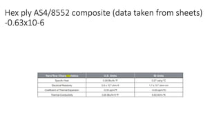
- 1. Hex ply AS4/8552 composite (data taken from sheets) -0.63x10⁻⁶
- 2. Moisture and Thermal Expansion Properties of Unidirectional Composite Materials and the Epoxy Matrix
- 3. Prediction of Thermal and Mechanical Properties of Glass-Epoxy Composite Laminates
- 4. Prediction of Thermal and Mechanical Properties of Glass-Epoxy Composite Laminates
- 5. Usually the cte of matrix is positive and larger than fiber cte When vf is less then 0.15,cte is dominated by matrix When vf is greater than and equal to 0.5,cte is dominated by thermal property of fiber
- 7. Thermal expansion behaviour depends on thermomechanical properties of its internal components
- 8. In literature people plotted thermal strains with temperature Temperature-dependent thermal expansion behavior of carbon fiber/ epoxy plain woven composites:
- 9. Aluminum and Aluminum Alloys. The dimensional change of aluminum and its alloys with a change of temperature is roughly twice that of the ferrous metals. The average CTE for commercially pure metal is 24 × 10–6/K (13 × 10–6/°F). Aluminum alloys are affected by the presence of silicon and copper, which reduce expansion, and magnesium, which increases it. Its high expansion should be considered when aluminum is used with other materials, especially in rigid structures, although the stresses developed are moderated by the low elastic modulus of aluminum. If dimensions are very large, as for example in a light alloy superstructure on a steel ship or where large pieces of aluminum are set on a steel framework or in masonry, then slip joints, plastic caulking, and other stress-relieving devices are usually needed. In the aluminum internal-combustion engine piston that works in an iron or steel cylinder, differential expansion is countered by the employment of low-expansion iron cylinder linings, or by split piston skirts and nonexpanding struts cast into the piston. Chapter 2 Thermal Expansion
- 10. The CTE of all samples was reduced by the addition of graphite. Graphite has a CTE of –1 ppm K–1 in-plane and 28 ppm K–1 through-plane [27]. Remarkably, the CTE of the sintered samples fell down to low or even negative values through-plane, while the in-plane reduction did not exceed 30% in comparison to the metal matrix. Firkowska et al. [12] observed a similar effect in copper–graphite composites with equivalent microstructure and attributed it to an in-plane stretch of the graphite crystal caused by the expansion of the metal matrix. Under consideration of the temperature dependence of the elastic constants and the effects of the cooling after sintering, the model predicts a shrink in the graphite crystal in the through-plane direction. This compensates the overall expansion of the sample along this axis. In our composites the higher CTE of the matrix led to higher in-plane CTE and showed, as expected from the model, a lower through-plane CTE than copper–matrix composites. Many metal matrices used here have too Composites of aluminum alloy and magnesium alloy with graphite showing low thermal expansion and high specific thermal conductivity
- 12. Coefficients of thermal expansion for different substrates and adhesives are presented in Table 17.1. The CTEs can be determined by dilatometry, by strain gauges (da Silva and Adams, 2008) or by a bi-material curved beam method (Yu et al., 2003; Loh et al., 2005). Let us look at the residual stresses in a joint with aluminium and a CFRP for example. With a negative thermal load, that is with a decrease in temperature from the stress-free temperature (TSF), and a compliant adhesive, the aluminium and the composite adherends can contract freely (see Fig. 17.1a). Note that, in fact, the length of the composite adherend does not change because its longitudinal CTE is close to zero. However, for a stiff adhesive in its glassy region, the adherends cannot contract freely so that the composite is subjected to a compressive axial load and the aluminium adherend is under tension (see Fig. 17.1b). However, the axial load causes bending of the joint as indicated in Fig. 17.1(c). The resultant stress will then be the sum of the uniform component caused by the axial load plus the linearly varying (through the thickness) contribution caused by bending. Whether the bending component is higher than the uniform direct component depends on the geometry and the material properties.
- 13. However, more important than the thermal stresses in the adherends are the stresses in the adhesive. For metal/composite joints for example, the metal tends to shrink as the temperature is decreased from the cure value (generally a high temperature) and this is partially resisted by the composite (lower CTE), thereby inducing residual bond stresses especially at the ends of the joint. One end has positive residual shear stresses and the other end has negative residual shear stresses (see Fig. 17.2). The thermal stresses are beneficial at one end of the joint but have the reverse effect on the other side of the joint. The thermal load DT is given by Equation 17.1:
- 14. Behavior of Al-Mg Alloy Subjected To Thermal Processing
- 15. Effect of Temperature on Material Properties of Carbon Fiber Reinforced Polymer (CFRP) Tendons: Experiments and Model Assessment
- 16. According to the ACI 440.1R [23], the coefficient of thermal expansion (CTE) of CFRP tendons is between −9.0 × 10⁻⁶/ ◦C and 0.0 × 10⁻⁶/ ◦C in the longitudinal direction. However, the variation of CTE with temperatures is not clear. The experimental results show that the longitudinal deformation of CFRP tendons decreased with the increase of temperature (Figure 5), which verifies the fact that the FRP composites shortened along the fiber direction at elevated temperatures [24]. This is mainly attributed to fact that carbon fibers shrink at elevated temperatures in the longitudinal direction [25]. With the increase of temperature, the shrinkage of carbon fibers dominated the longitudinal deformation of CFRP tendons due to the softening of the resin. When the temperature was low, the CTE decreased slowly. As the temperature rose, the resin of FRP composites began to soften, and the CTE of CFRP tendons decreased to a larger negative value. Especially, when the temperature exceeded 200 ◦C, the CTE decreased rapi
- 17. α = −1.5 × 10⁻⁶ (T − 23) 3 + 3.17 × 10⁻⁴ (T − 23) 2 − 2.44 × 10⁻² (T − 23) + 0.015 creased to a larger negative value. Especially, when the temperature exceeded 200 °C, the CTE decreased rapidly. Finally, the longitudinal deformation of CFRP tendons was unstable after 300 °C due to the decomposition of the resin, resulting in the failure of obtaining its thermal expansion properties. Based on the experimental data, the longitudinal CTE (10−6/°C) of CFRP tendons is proposed in the form of polynomial function (Equat Effect of Temperature on Material Properties of Carbon Fiber Reinforced Polymer (CFRP) Tendons: Experiments and Model Assessment
- 18. Evaluation of thermal expansion coefficient of carbon fiber reinforced composites using electronic speckle interferometry
- 20. Testing of adherents • Properties of carbon fiber • Thermo-mechanical properties of carbon fiber • Tensile strength testing of composite • Fatigue strength of composite • Three point bending • Four point bending • DMA • Fiber volume fraction of composite • DSc of composite • Tensile strength testing of metal alloy • Three point bending • Tensile strength of resin araldite 564 and araldite 2011 Discuss with dr. khubab too
- 21. Properties of materials from literature Type of material Aluminum alloy Carbon fiber Glass fiber Ly 564/22962 matrix Araldite 2011 Adhesive Type Al 7075-T6 AS4 12 K (12000 filaments) E glass Ly 564 araldite 2011 GSm Glass Transition Temperature (Tg) 138 oc when cure at 80 oc for at 1 hour + 150 oc for2 hours Ultimate Tensile strength o f material 510-540 MPa 4413 MPa 75-80 MPa (15 min at 120 + 2 hr at 150 oc) Tensile strength of composite in 0 direction 2205 MPa Flexural strength in 0 1889 MPa
- 22. Properties of materials from literature continued Type of material Aluminum alloy Carbon fiber Glass fiber Ly 564 matrix Araldite 2011 Adhesive Soilidus 470 oC Liquidus 635oC Typilcal cure
- 23. Points of discussion on adhesive post curing 1. Difference in post curing under compression molding and oven 2. Post curing temperature will be different of binder and composite
- 24. New plan for dma and tma
- 25. Compression mode in TMA • To Check Viscoelastic behabiur of lap joints • Temperature ramp 25 to 200 • Temperature
- 26. Compression mode on TMA Number of samples Force (maximum applied force) Temperature (ramp) Surface treatment Output (creep) 1 Maximum force 25-150 1 (comp) 2 Maximum force 25-150 2 (comp) 3 Maximum force 25-150 3 (comp) 4 Maximum force 25-150 4 (metal) 5 Maximum force 25-150 5 (metal) 6 80% of maximum force 25-150 1 (comp) 7 80% of maximum force 25-150 2 (comp) 8 80% of maximum force 25-150 3 (comp)