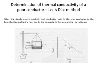
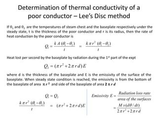
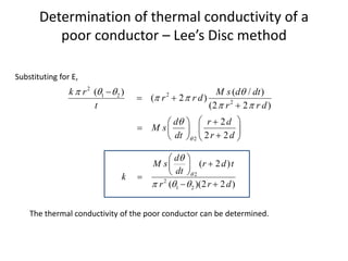
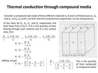
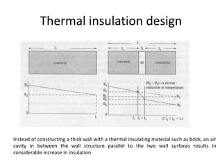
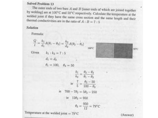
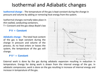
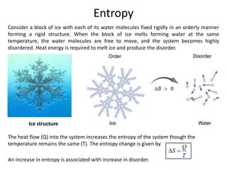
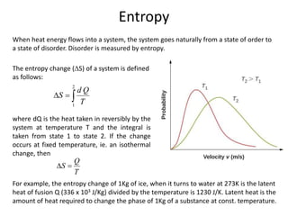
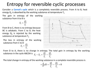
The document discusses various topics related to thermal physics including:
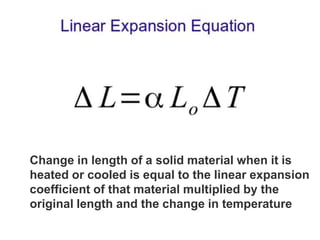
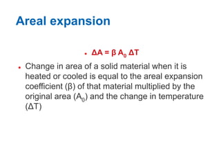
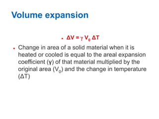
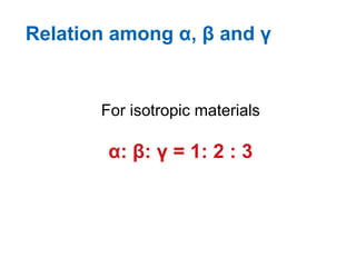
1. Thermal expansion - how materials change shape, size, and density with changes in temperature. Most materials expand on heating and contract on cooling.
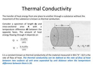
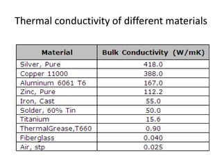
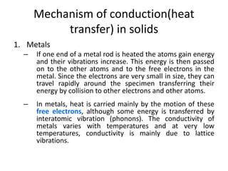
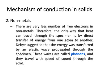
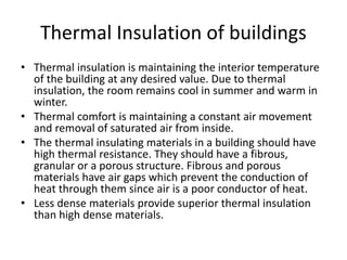
2. Thermal conductivity - the rate at which heat is transferred through a material by conduction. Metals have high conductivity due to free electrons, while in non-metals heat is transferred by phonon vibrations.
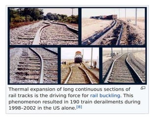
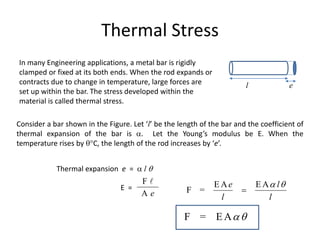
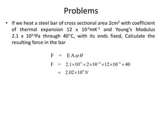
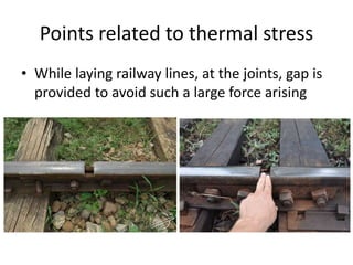
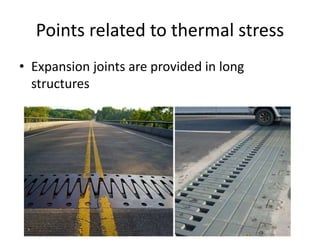
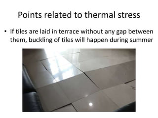
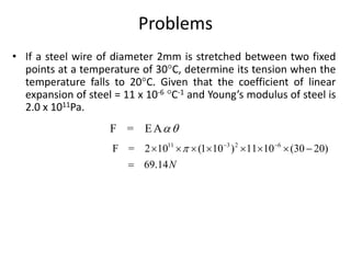
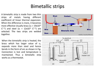
3. Thermal stress - the stresses that develop in materials with rigid boundaries when they expand or contract due to temperature changes. Examples of applications involving thermal stress are also discussed.