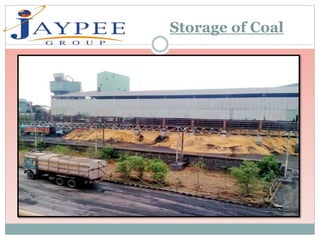
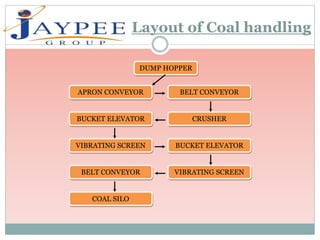
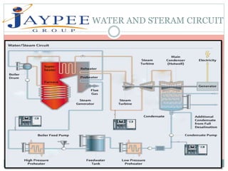
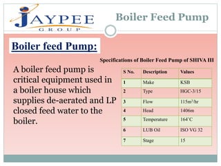
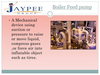
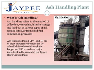
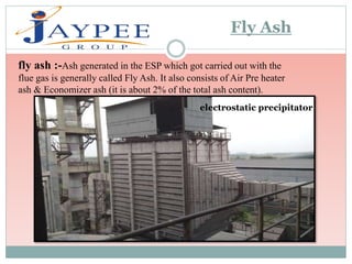
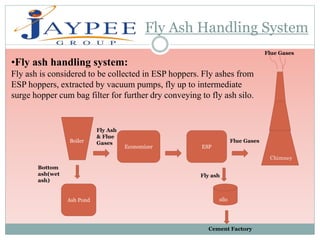
A
Presentation on
THERMAL POWER PLANT
PRESENTED BY-PRESENTED TO -
Dr. A.K. Panday
Mr. A.K. Sahoo
Arjun Gupta (134108)
Amit Mishra (134107)
Sunil Kumar kushwah (134138)
Tej pratap Yadav (134139)
Today I am going to tell you about jaypee rewa
Cement plant . it is located in rewa (M.P).It since 1986
.The main purpose of the plant of the plant is to make the
cement .In 2003 & 2006they had install two captive power
plant also the first power plant is 25MW and second
captive power plant 38.5 mw
INTRODUCTION
 Dissolved salts and minerals in water can we removed
completely by a series of cation and anion exchangers.
Most of the steam generating plant use this process for
external treatment of feed water. Water treatment in this
method is done at demineralisation plant.
Collidal slica can not removed in DM plant .
Demineralising Water Plant
D.M. Plant
 Un dissolved suspended impurities like-mud, sand,
sediment etc.
Dissolved salts and minerals, e.g. carbonate, bi-
carbonate, silicate, and nitrate, ca/mg.
Dissolved gases such as oxygen, carbon dioxide, etc.
Other materials, like acid, oil, etc.
Types of impurities in Water
D.M. Plant
River water contains insoluble or undissolved
Suspended matter like mud, sediment and sand.. The
Turbidity of this water is high.
UNDISSOLVED MATTER CAN BE REMOVED FROM
WATER FOLLOWING THREE METHAD-
Sedimentation
Filtration
Coagulation
D.M. Plant
Removal of undissolved impurities in water
FLOW DIAGRAM OF DM PLANT
 6River RESERVIOR TANK
(4000M³ )
SOLID COTACT
CLARIFIER
(50m³)
CLARIFIER
STORAGE
TANK (48M³)
MGF
(45m3/hr
)
U.F.
40
M³/h
U.F. TANK
(35M³)
R.O. FILTER
MB
(20M³)
DM WATER
STORAGE TANK
(6000M³)
D.M. Plant
Basket Filter
PARTS OF DM PLANT
 RAW WATER STORAGE TANK
 SOLID CONACT REACTIFIRE
 CLARIFIRE STORAGE TANK
 MULTIGRATE FILTER
 ULTRA FILTRATION
 REVERSE OSMOSIS
 STRONGE ACID CATION
 STRONG BASE ANION
 MIXED BED
 DM STORAGE TANK
D.M. Plant
MULTIGRADE FILTER:
In this arrangement of
small sand and big sand
which is removed dust,
seal dust, turbidity, mud
suspended solid and
impurities.
D.M. Plant
ULTRA FILTRATION :
Ultra filtration is very effective
filtration technology for the
separation , concentration and
purification with complete
removal of pathogenic bacteria
and suspended solid.
The pore size of the membrane is
0.01 micron which removes
turbidity , bacteria and collodial
slica
D.M. Plant
REVERS OSMOSIS :
It has semi permable
membrane which allow only
solute particles flow throw
high pressure pump (15
kg/cm²). Ratio of the R.O.
system 75% product and 25%
waste. Membrane size 0.001
micron.
D.M. Plant
PROCESS OF DIMINERILISATION
Raw water contains salts of calcium and magnesium
chloride, sulphate, nitrate, carbonate, bi-carbonates
and silicates these salts are having-
Cations like- Ca+, Mg+, Na+ etc.
Anions like-Co3-, So4-, Cl-, Sio3- etc.
D.M. Plant
Coal Handling Plant
Coal is the basic and the oldest raw
material used on large scale throughout the
world. Throughout history, coal has been a
useful resource. It is primarily burned for
the production of electricity and/or heat is
also used for industrial purposes, such as
refining metals. A fossil fuel, coal forms
when dead plant matter is converted into
peat, which in turn is converted into
lignite, then sub bituminous coal, and
lastly anthracite. This involves biological
and geological processes that take place
over a long period.
“THE COAL IS BLACK DIAMOND”
Storage of Coal
Layout of Coal handling
DUMP HOPPER
APRON CONVEYOR BELT CONVEYOR
CRUSHERBUCKET ELEVATOR
VIBRATING SCREEN BUCKET ELEVATOR
VIBRATING SCREENBELT CONVEYOR
COAL SILO
S No. DESCRIPTION
S
OLD NEW
1. Primary Coal
Crusher
----NA---- 80TPH, Model-APKM1313
(L&T)
2. Vibrating
Screens
150TPH, Model-SL78-75-2-25
Qty-2 (ICIL)
150TPH, Model-SL78-75-2-25
Qty-2 (ICIL)
3. Bucket Elevator 150TPH 50TPH
(MECP) (MECP)
190TPH
(TECPRO)
4. Apron
Conveyors
150 TPH, Model-T14
(L&T)
150 TPH, Model-T14
(L&T)
5. Belt Conveyors 150TPH, 800mm wide
(FENNER)
150TPH, 1000mm wide
(HINDUSTAN RUBBER)
6. Coal Silo 1200 Ton for crushed coal height 22m 1200 Ton for crushed coal height
22m
7. Bag Filters 8000m3/h ALOSTOM 4000m3/h BELTEC
specification of Belt Conveyor
WATER AND STERAM CIRCUIT
Boiler is a closed vessel having minimum capacity of 22.75 L along
with the mountings in which water or other fluid is heated. The
heated or vaporized fluid exits the boiler for use in various
processes or heating applications, including boiler-based power
generation, cooking.
Types of Boiler:
•Fire Tube Boiler
•Water Tube Boiler
1-FBC-
o AFBC,CFBC AND PFBC
Boiler
C APACITY OF BOILER
Type Water type AFBC AND CFBC
Make Isec john thompson & TKIL
CAPACITY 60 TPH &170 TPH
SATURATED PRESSURE 87 ATA & 87 ATA
SATURATED TEMPRATURE 515±5◦C
COMMISSIONED ON DES 2003 & 2006
The steam turbine is a prime-mover in which the
potential energy of the steam in transformed into kinetic
energy, and latter in its turn is transformed into the
mechanical energy of rotation of the turbine shaft. The
turbine shaft, directly or with the help of a reduction
gearing, is connected with rotor of generator.
Classification of Turbines:
The steam turbines are mainly divided into two groups as –
1-water turbine
2-wind turbine
3-steam turbine
 impulse turbine
DESCRIPTION SHIVA 1 SHIVA 3
MAKE BHEL Hyderabad BHEL Hyderabad
RATING 27000 KW 38500 KW
RATED SPEED 7700 RPM 6300 RPM
NO. OF STAGES IMPULSE 01
RECATION 19
IMPULSE 1
RECATION 24HP/3LP
INLET STEAM PRE. 84 Kg/cm2 84Kg/cm2
INLET STEEM TEM. 510°C 510°C
EXAHAUST PRE. 0.78Kg/cm2 0.78Kg/cm2
EXAHAUST STEAM TEM. 90°C 55-58
TURBINE OIL SP46T SERVO32T
MAX WHEEL CHAMBER PRE. 54.2Kg/cm2 66.7
COMMISSIONED ON 30 SEP. 2003 16 AUG. 2006
Specification of Boiler
MOUNTING ACCESSEORIES
1- SAFTY VALVE AIR PRE-HEATER
2- WATER LAVEL INDICATOR ECONOMISER
3-PRESSURE GAUGE SUPER HEATER
4-FUSIBLE PLUG INJECTOR
5-STEEM STOP VALVE FEED PUMP
6-FEED CHECK VALVE
7-MAN AND MUD HOLE
Mounting and accesseories
FANS ARE USED
IN POWER PLANT
 ID FAN-This fan is used to create negative pressure
in the furnace.
 FD FAN-Forced draft fans is to provide a positive
pressure to a system.
 Steam after rotating
steam turbine comes to
condenser. Condenser
refers here to the shell
and tube heat
exchanger (or surface
condenser) installed at
the outlet of every
steam turbine in
Thermal power stations
of utility companies
generally.
CONDENSER
The main purposes of the condenser are to condense the
exhaust steam from the turbine for reuse in the cycle .
Increased plant efficiency .
Reduced steam flow It is therefore very advantageous to
operate the condenser at the lowest possible pressure.
CONDENSER
Purpose of condenser :
CONDENSER
Function of condenser :
Function of the condenser is to create a vacuum by
condensing steam.
 for re-use as the feed water supply to the steam
generator.
CONDENSER
Operation of condenser :
The main heat transfer mechanisms in a surface condenser are the
condensing of saturated steam on the outside of the tubes and the
heating of the circulating water inside the tubes.
 Thus for a given circulating water flow rate, the water inlet
temperature to the condenser determines the operating pressure of the
condenser.
As this temperature is decreased, the condenser pressure will also
decrease.
 As described above, this decrease in the pressure will increase the
plant output and efficiency.
Due to the fact that a surface condenser operates under vacuum,
noncondensable gases will migrate towards the condenser.
Air Cooled Condenser
CONDENSER
Air Cooled condenser :
Air cooled condenser belong to the dry
cooling system. In direct dry cooling
steam from the steam turbine passes
through air cooled fin tube.
S No.
Description Values
1 Make GEI-HAMON Bhopal
2 T/G Exhaust Steam 85.4 TPH at 0.78kg/cm2
3 Fans 6
4 Air Flow/ Fan 584.1 cum/s
5 RPM of motor/ fan 1480/84 max
6 Design for ambient temperature 42˚C
Specification of condenser of SHIVA I
Condensate Storage Tank
S
NO
.
Description Values
1 Type Air Cooled Condenser
2 Steam Flow 86 TPH
3 Steam
Temperature
61.7˚C
4 Steam Pressure 0.2 ATA
5 No. of fans 4(K Fans) 2(D Fans)
6 Speed 97.9 rpm
7 Flow 534.14(K Fans) 531.88(D
Fans)
8 Motor Speed 132kW/1475 rpm
Specification of condenser of SHIVA III
Boiler Feed Pump
A boiler feed pump is
critical equipment used in
a boiler house which
supplies de-aerated and LP
closed feed water to the
boiler.
S No. Description Values
1 Make KSB
2 Type HGC-3/15
3 Flow 115m3/hr
4 Head 1406m
5 Temperature 164˚C
6 LUB Oil ISO VG 32
7 Stage 15
Specifications of Boiler Feed Pump of SHIVA III
Boiler feed Pump:
Boiler Feed pump
 A Mechanical
device using
suction or
pressure to raise
or move liquid,
compress gases
,or force air into
inflatable object
such as tires.
Ash Handling Plant
 What is Ash Handling?
Ash handling refers to the method of
collection, conveying, interim storage
and load out of various types of ash
residue left over from solid fuel
combustion processes
Ash Handling Plant I CPP I and III are
of great importance because the fly
ash which is collected through the
hoppers of ESP is used as a major
ingredient in the cement at the Jaypee
Rewa Cement Plant.
Fly Ash Silo
Fly Ash
fly ash :-Ash generated in the ESP which got carried out with the
flue gas is generally called Fly Ash. It also consists of Air Pre heater
ash & Economizer ash (it is about 2% of the total ash content).
electrostatic precipitator
Internal View of ESP
Fly Ash Handling System
Fly Ash
& Flue
Gases
Economizer ESP
Bottom
ash(wet
ash)
Ash Pond
Boiler
silo
Chimney
Fly ash
Flue Gases
Flue Gases
Cement Factory
•Fly ash handling system:
Fly ash is considered to be collected in ESP hoppers. Fly ashes from
ESP hoppers, extracted by vacuum pumps, fly up to intermediate
surge hopper cum bag filter for further dry conveying to fly ash silo.
•Bottom Ash Handling System: Bottom ash resulting
from the combustion of coal in the boiler shall fall into the
over ground, refractory lined, double V section type bottom
ash hopper having a hold up volume to store bottom ash and
economizer ash of maximum allowable condition with the
rate specified. The slurry formed shall be transported to
slurry pump through pipes.
THANK YOU

Sunil- Thermal Power Plant

  • 1.
    A Presentation on THERMAL POWERPLANT PRESENTED BY-PRESENTED TO - Dr. A.K. Panday Mr. A.K. Sahoo Arjun Gupta (134108) Amit Mishra (134107) Sunil Kumar kushwah (134138) Tej pratap Yadav (134139)
  • 2.
    Today I amgoing to tell you about jaypee rewa Cement plant . it is located in rewa (M.P).It since 1986 .The main purpose of the plant of the plant is to make the cement .In 2003 & 2006they had install two captive power plant also the first power plant is 25MW and second captive power plant 38.5 mw INTRODUCTION
  • 3.
     Dissolved saltsand minerals in water can we removed completely by a series of cation and anion exchangers. Most of the steam generating plant use this process for external treatment of feed water. Water treatment in this method is done at demineralisation plant. Collidal slica can not removed in DM plant . Demineralising Water Plant D.M. Plant
  • 4.
     Un dissolvedsuspended impurities like-mud, sand, sediment etc. Dissolved salts and minerals, e.g. carbonate, bi- carbonate, silicate, and nitrate, ca/mg. Dissolved gases such as oxygen, carbon dioxide, etc. Other materials, like acid, oil, etc. Types of impurities in Water D.M. Plant
  • 5.
    River water containsinsoluble or undissolved Suspended matter like mud, sediment and sand.. The Turbidity of this water is high. UNDISSOLVED MATTER CAN BE REMOVED FROM WATER FOLLOWING THREE METHAD- Sedimentation Filtration Coagulation D.M. Plant Removal of undissolved impurities in water
  • 6.
    FLOW DIAGRAM OFDM PLANT  6River RESERVIOR TANK (4000M³ ) SOLID COTACT CLARIFIER (50m³) CLARIFIER STORAGE TANK (48M³) MGF (45m3/hr ) U.F. 40 M³/h U.F. TANK (35M³) R.O. FILTER MB (20M³) DM WATER STORAGE TANK (6000M³) D.M. Plant Basket Filter
  • 7.
    PARTS OF DMPLANT  RAW WATER STORAGE TANK  SOLID CONACT REACTIFIRE  CLARIFIRE STORAGE TANK  MULTIGRATE FILTER  ULTRA FILTRATION  REVERSE OSMOSIS  STRONGE ACID CATION  STRONG BASE ANION  MIXED BED  DM STORAGE TANK D.M. Plant
  • 8.
    MULTIGRADE FILTER: In thisarrangement of small sand and big sand which is removed dust, seal dust, turbidity, mud suspended solid and impurities. D.M. Plant
  • 9.
    ULTRA FILTRATION : Ultrafiltration is very effective filtration technology for the separation , concentration and purification with complete removal of pathogenic bacteria and suspended solid. The pore size of the membrane is 0.01 micron which removes turbidity , bacteria and collodial slica D.M. Plant
  • 10.
    REVERS OSMOSIS : Ithas semi permable membrane which allow only solute particles flow throw high pressure pump (15 kg/cm²). Ratio of the R.O. system 75% product and 25% waste. Membrane size 0.001 micron. D.M. Plant
  • 11.
    PROCESS OF DIMINERILISATION Rawwater contains salts of calcium and magnesium chloride, sulphate, nitrate, carbonate, bi-carbonates and silicates these salts are having- Cations like- Ca+, Mg+, Na+ etc. Anions like-Co3-, So4-, Cl-, Sio3- etc. D.M. Plant
  • 12.
    Coal Handling Plant Coalis the basic and the oldest raw material used on large scale throughout the world. Throughout history, coal has been a useful resource. It is primarily burned for the production of electricity and/or heat is also used for industrial purposes, such as refining metals. A fossil fuel, coal forms when dead plant matter is converted into peat, which in turn is converted into lignite, then sub bituminous coal, and lastly anthracite. This involves biological and geological processes that take place over a long period. “THE COAL IS BLACK DIAMOND”
  • 13.
  • 14.
    Layout of Coalhandling DUMP HOPPER APRON CONVEYOR BELT CONVEYOR CRUSHERBUCKET ELEVATOR VIBRATING SCREEN BUCKET ELEVATOR VIBRATING SCREENBELT CONVEYOR COAL SILO
  • 15.
    S No. DESCRIPTION S OLDNEW 1. Primary Coal Crusher ----NA---- 80TPH, Model-APKM1313 (L&T) 2. Vibrating Screens 150TPH, Model-SL78-75-2-25 Qty-2 (ICIL) 150TPH, Model-SL78-75-2-25 Qty-2 (ICIL) 3. Bucket Elevator 150TPH 50TPH (MECP) (MECP) 190TPH (TECPRO) 4. Apron Conveyors 150 TPH, Model-T14 (L&T) 150 TPH, Model-T14 (L&T) 5. Belt Conveyors 150TPH, 800mm wide (FENNER) 150TPH, 1000mm wide (HINDUSTAN RUBBER) 6. Coal Silo 1200 Ton for crushed coal height 22m 1200 Ton for crushed coal height 22m 7. Bag Filters 8000m3/h ALOSTOM 4000m3/h BELTEC specification of Belt Conveyor
  • 16.
  • 17.
    Boiler is aclosed vessel having minimum capacity of 22.75 L along with the mountings in which water or other fluid is heated. The heated or vaporized fluid exits the boiler for use in various processes or heating applications, including boiler-based power generation, cooking. Types of Boiler: •Fire Tube Boiler •Water Tube Boiler 1-FBC- o AFBC,CFBC AND PFBC Boiler
  • 18.
    C APACITY OFBOILER Type Water type AFBC AND CFBC Make Isec john thompson & TKIL CAPACITY 60 TPH &170 TPH SATURATED PRESSURE 87 ATA & 87 ATA SATURATED TEMPRATURE 515±5◦C COMMISSIONED ON DES 2003 & 2006
  • 19.
    The steam turbineis a prime-mover in which the potential energy of the steam in transformed into kinetic energy, and latter in its turn is transformed into the mechanical energy of rotation of the turbine shaft. The turbine shaft, directly or with the help of a reduction gearing, is connected with rotor of generator. Classification of Turbines: The steam turbines are mainly divided into two groups as – 1-water turbine 2-wind turbine 3-steam turbine  impulse turbine
  • 20.
    DESCRIPTION SHIVA 1SHIVA 3 MAKE BHEL Hyderabad BHEL Hyderabad RATING 27000 KW 38500 KW RATED SPEED 7700 RPM 6300 RPM NO. OF STAGES IMPULSE 01 RECATION 19 IMPULSE 1 RECATION 24HP/3LP INLET STEAM PRE. 84 Kg/cm2 84Kg/cm2 INLET STEEM TEM. 510°C 510°C EXAHAUST PRE. 0.78Kg/cm2 0.78Kg/cm2 EXAHAUST STEAM TEM. 90°C 55-58 TURBINE OIL SP46T SERVO32T MAX WHEEL CHAMBER PRE. 54.2Kg/cm2 66.7 COMMISSIONED ON 30 SEP. 2003 16 AUG. 2006 Specification of Boiler
  • 21.
    MOUNTING ACCESSEORIES 1- SAFTYVALVE AIR PRE-HEATER 2- WATER LAVEL INDICATOR ECONOMISER 3-PRESSURE GAUGE SUPER HEATER 4-FUSIBLE PLUG INJECTOR 5-STEEM STOP VALVE FEED PUMP 6-FEED CHECK VALVE 7-MAN AND MUD HOLE Mounting and accesseories
  • 22.
    FANS ARE USED INPOWER PLANT  ID FAN-This fan is used to create negative pressure in the furnace.  FD FAN-Forced draft fans is to provide a positive pressure to a system.
  • 23.
     Steam afterrotating steam turbine comes to condenser. Condenser refers here to the shell and tube heat exchanger (or surface condenser) installed at the outlet of every steam turbine in Thermal power stations of utility companies generally. CONDENSER
  • 24.
    The main purposesof the condenser are to condense the exhaust steam from the turbine for reuse in the cycle . Increased plant efficiency . Reduced steam flow It is therefore very advantageous to operate the condenser at the lowest possible pressure. CONDENSER Purpose of condenser :
  • 25.
    CONDENSER Function of condenser: Function of the condenser is to create a vacuum by condensing steam.  for re-use as the feed water supply to the steam generator.
  • 26.
    CONDENSER Operation of condenser: The main heat transfer mechanisms in a surface condenser are the condensing of saturated steam on the outside of the tubes and the heating of the circulating water inside the tubes.  Thus for a given circulating water flow rate, the water inlet temperature to the condenser determines the operating pressure of the condenser. As this temperature is decreased, the condenser pressure will also decrease.  As described above, this decrease in the pressure will increase the plant output and efficiency. Due to the fact that a surface condenser operates under vacuum, noncondensable gases will migrate towards the condenser.
  • 27.
    Air Cooled Condenser CONDENSER AirCooled condenser : Air cooled condenser belong to the dry cooling system. In direct dry cooling steam from the steam turbine passes through air cooled fin tube. S No. Description Values 1 Make GEI-HAMON Bhopal 2 T/G Exhaust Steam 85.4 TPH at 0.78kg/cm2 3 Fans 6 4 Air Flow/ Fan 584.1 cum/s 5 RPM of motor/ fan 1480/84 max 6 Design for ambient temperature 42˚C Specification of condenser of SHIVA I
  • 28.
    Condensate Storage Tank S NO . DescriptionValues 1 Type Air Cooled Condenser 2 Steam Flow 86 TPH 3 Steam Temperature 61.7˚C 4 Steam Pressure 0.2 ATA 5 No. of fans 4(K Fans) 2(D Fans) 6 Speed 97.9 rpm 7 Flow 534.14(K Fans) 531.88(D Fans) 8 Motor Speed 132kW/1475 rpm Specification of condenser of SHIVA III
  • 29.
    Boiler Feed Pump Aboiler feed pump is critical equipment used in a boiler house which supplies de-aerated and LP closed feed water to the boiler. S No. Description Values 1 Make KSB 2 Type HGC-3/15 3 Flow 115m3/hr 4 Head 1406m 5 Temperature 164˚C 6 LUB Oil ISO VG 32 7 Stage 15 Specifications of Boiler Feed Pump of SHIVA III Boiler feed Pump:
  • 30.
    Boiler Feed pump A Mechanical device using suction or pressure to raise or move liquid, compress gases ,or force air into inflatable object such as tires.
  • 31.
    Ash Handling Plant What is Ash Handling? Ash handling refers to the method of collection, conveying, interim storage and load out of various types of ash residue left over from solid fuel combustion processes Ash Handling Plant I CPP I and III are of great importance because the fly ash which is collected through the hoppers of ESP is used as a major ingredient in the cement at the Jaypee Rewa Cement Plant. Fly Ash Silo
  • 32.
    Fly Ash fly ash:-Ash generated in the ESP which got carried out with the flue gas is generally called Fly Ash. It also consists of Air Pre heater ash & Economizer ash (it is about 2% of the total ash content). electrostatic precipitator
  • 33.
  • 34.
    Fly Ash HandlingSystem Fly Ash & Flue Gases Economizer ESP Bottom ash(wet ash) Ash Pond Boiler silo Chimney Fly ash Flue Gases Flue Gases Cement Factory •Fly ash handling system: Fly ash is considered to be collected in ESP hoppers. Fly ashes from ESP hoppers, extracted by vacuum pumps, fly up to intermediate surge hopper cum bag filter for further dry conveying to fly ash silo.
  • 35.
    •Bottom Ash HandlingSystem: Bottom ash resulting from the combustion of coal in the boiler shall fall into the over ground, refractory lined, double V section type bottom ash hopper having a hold up volume to store bottom ash and economizer ash of maximum allowable condition with the rate specified. The slurry formed shall be transported to slurry pump through pipes.
  • 36.