Downloaded 350 times

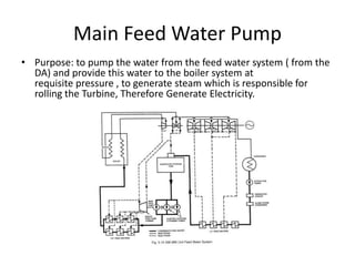
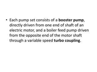
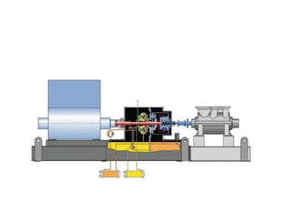
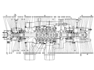
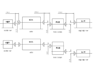
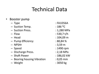
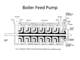
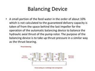
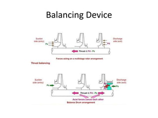
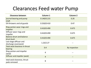
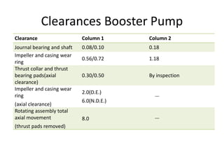
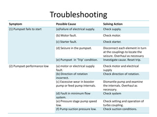
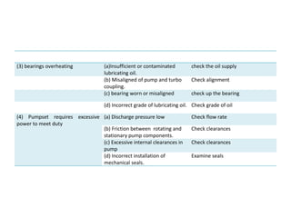
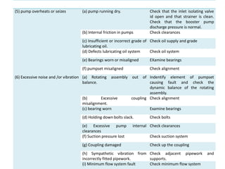

The document provides information about the boiler feed water pump system used in a power plant, including its purpose, components, technical specifications, maintenance procedures, and troubleshooting guidelines. The system consists of a booster pump and larger feed water pump coupled together and driven by a single electric motor. Key components are described in detail, such as the pumps, turbo coupling, motor, and balancing device. Periodic maintenance tasks and clearances are outlined. Common issues that may arise are identified along with recommended solutions.