The document summarizes the design of the SlimSAR system, a small synthetic aperture radar designed for operation on small unmanned aircraft systems. Key points include:
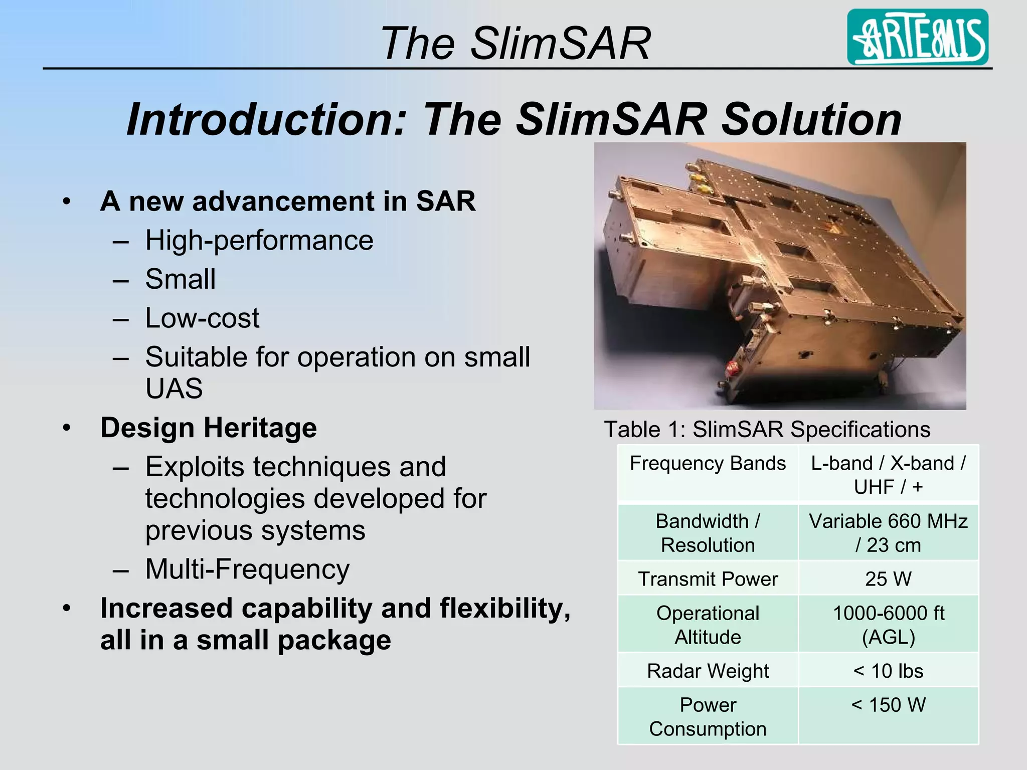
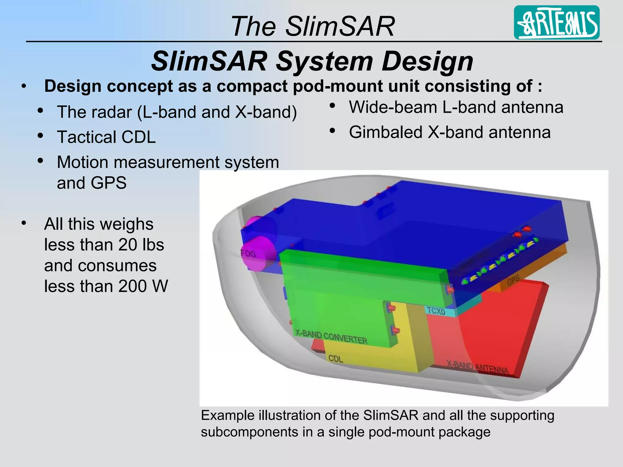
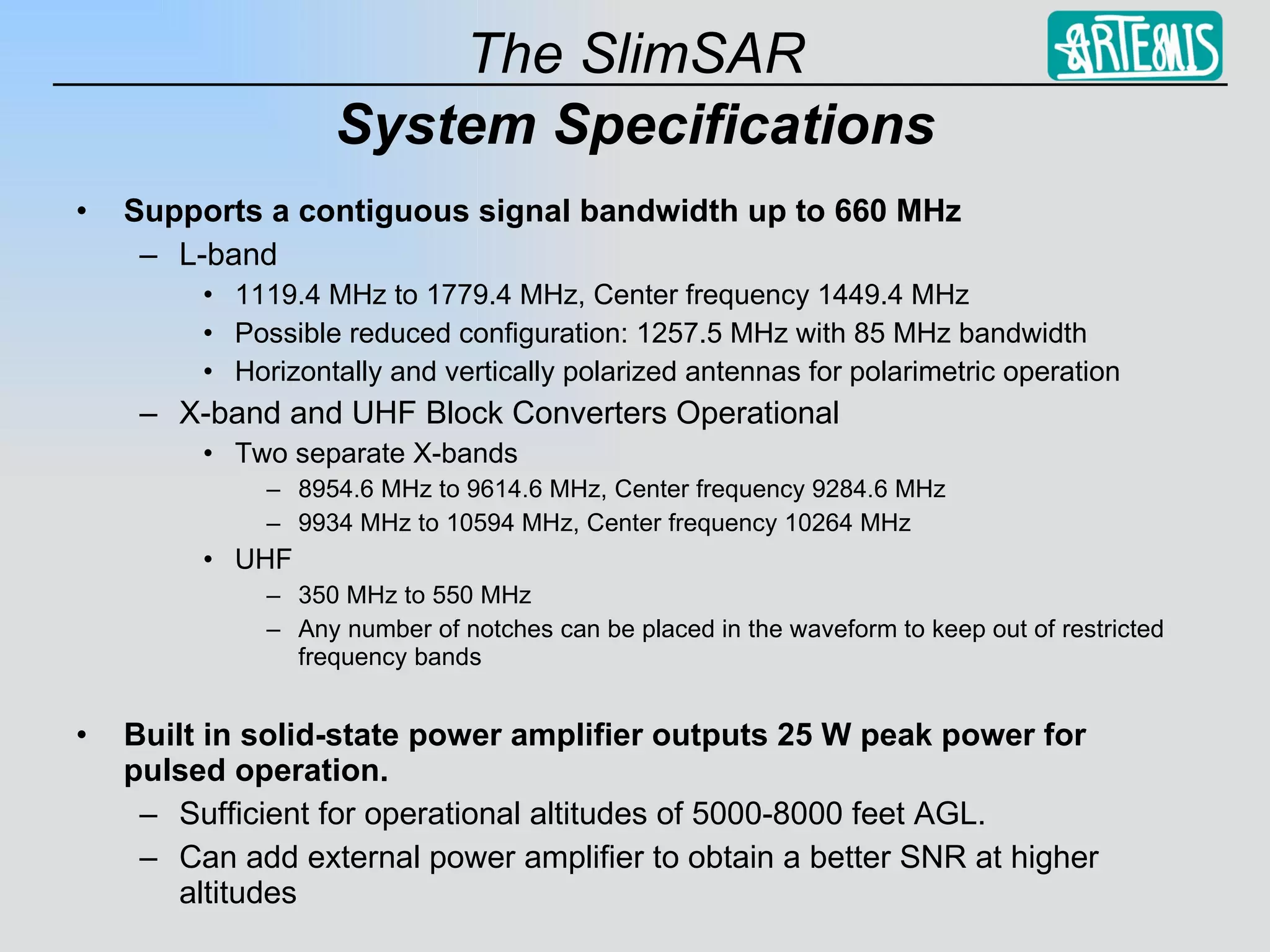
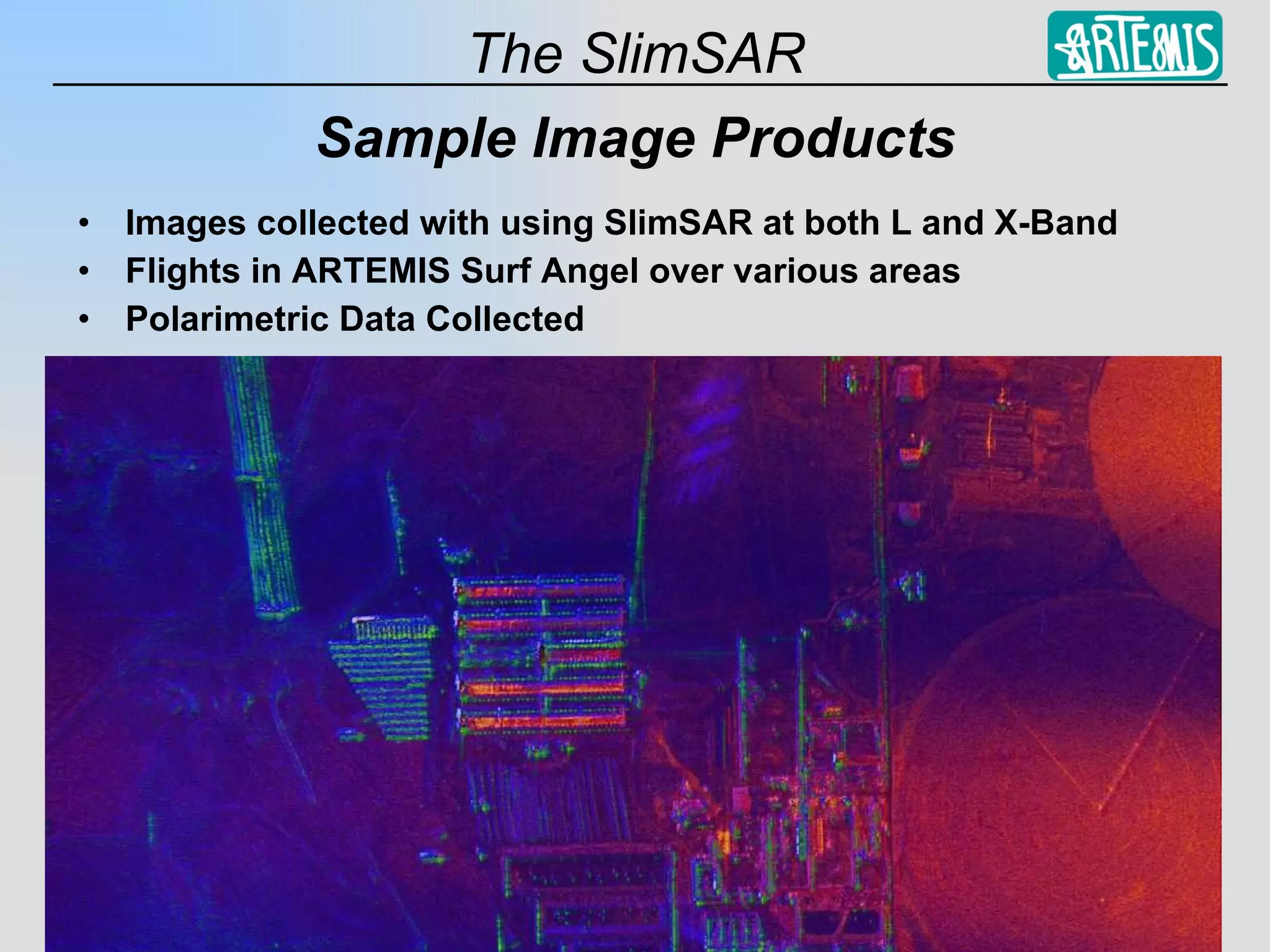
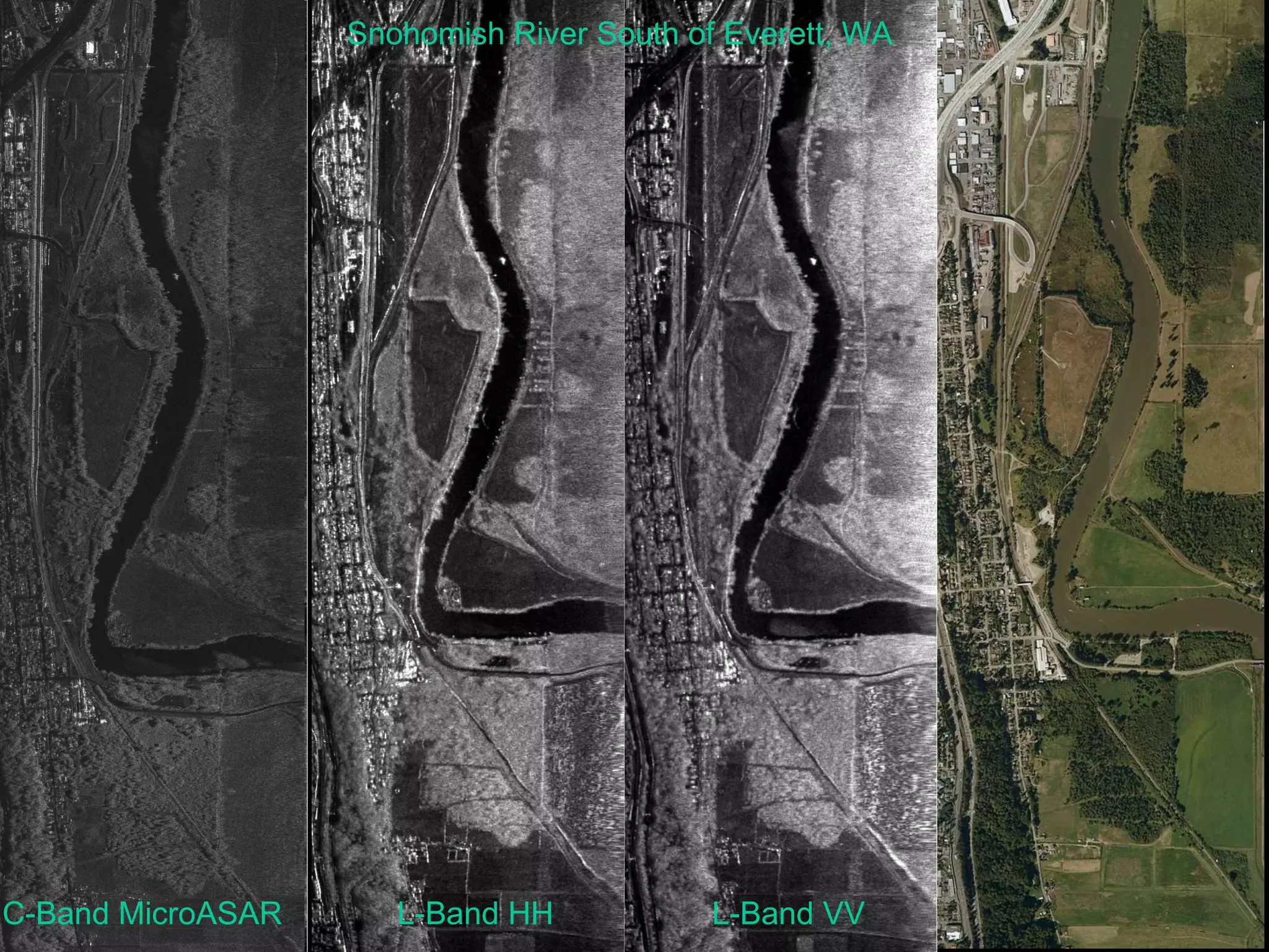
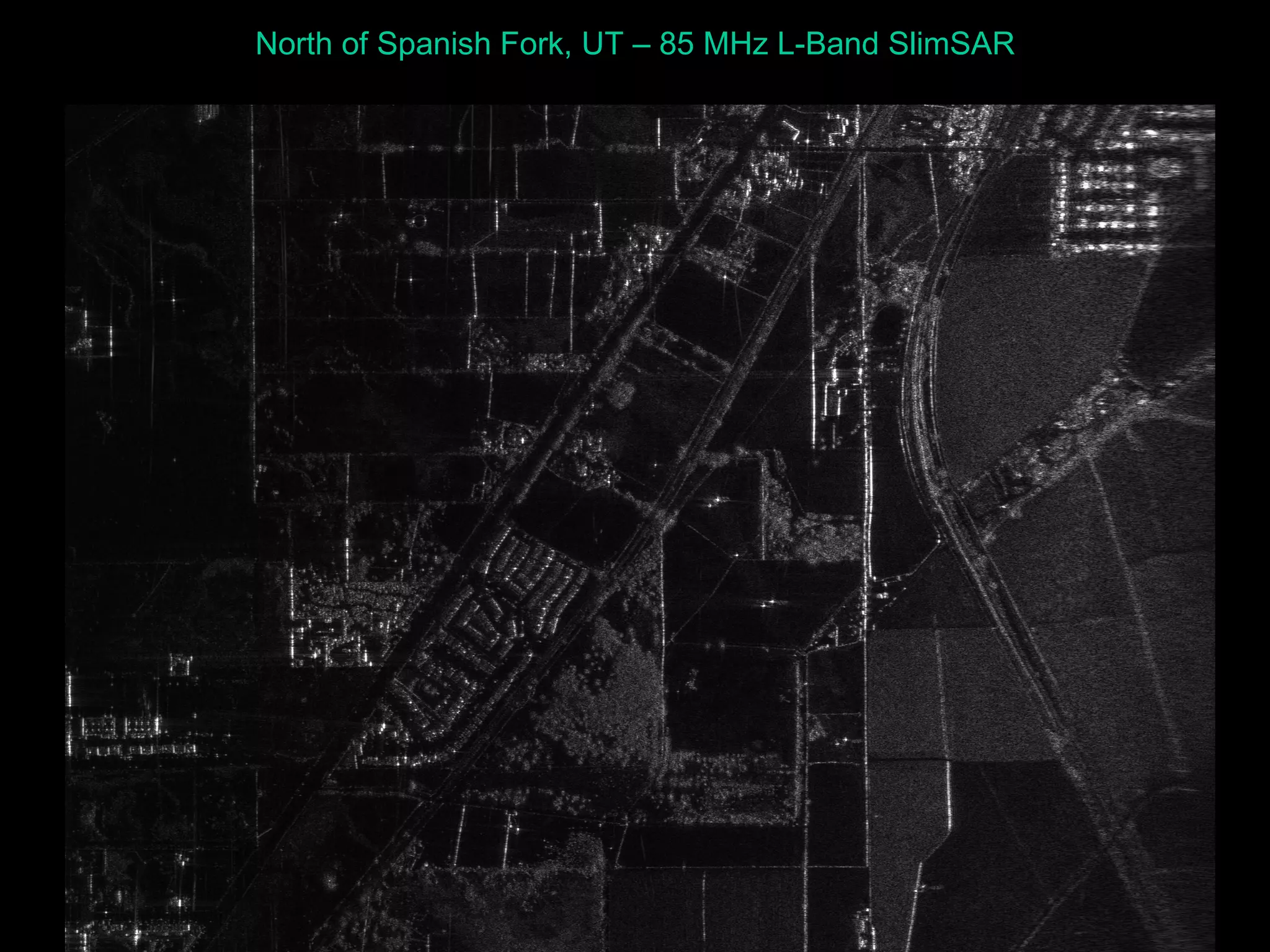
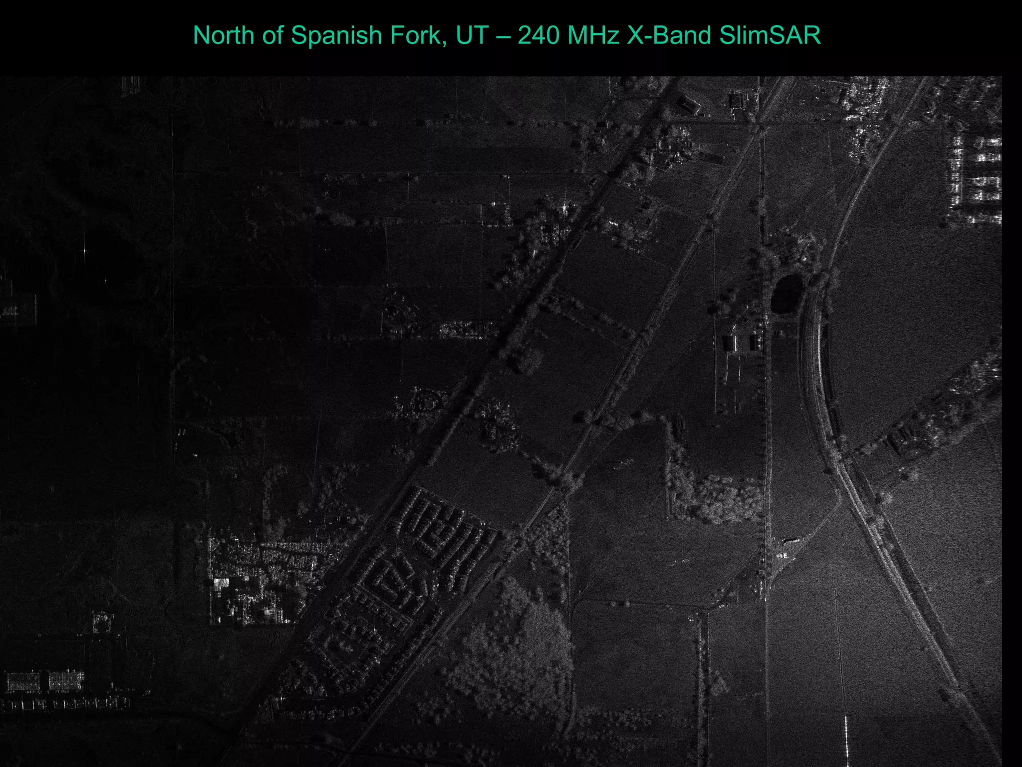
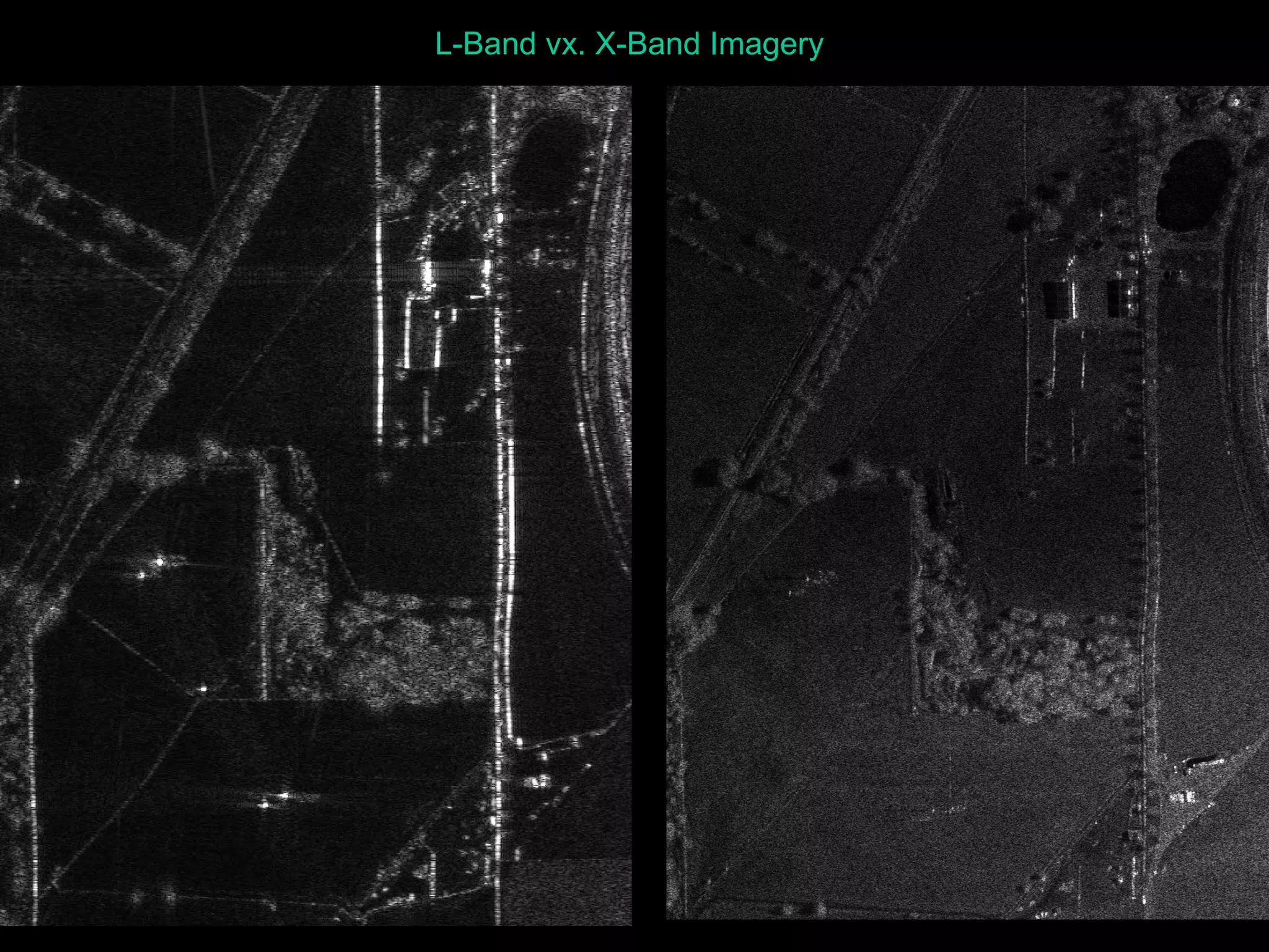
1) SlimSAR is a multi-frequency SAR that operates at L-band, X-band, and UHF with a bandwidth up to 660 MHz and weighs less than 10 lbs.
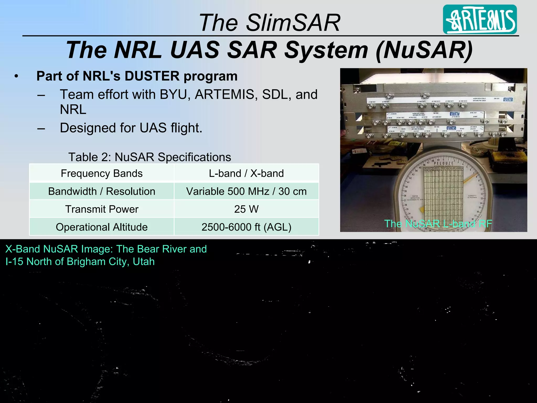
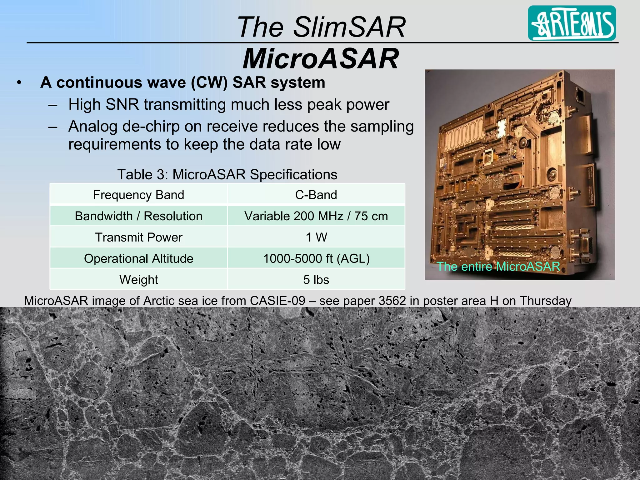
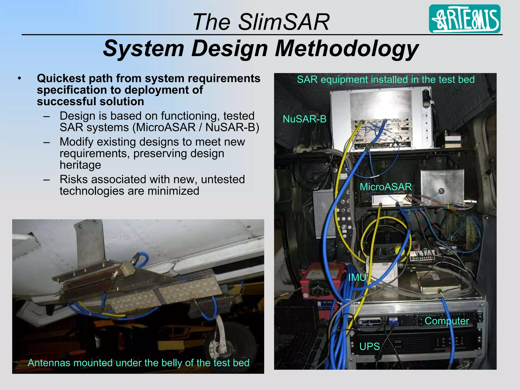
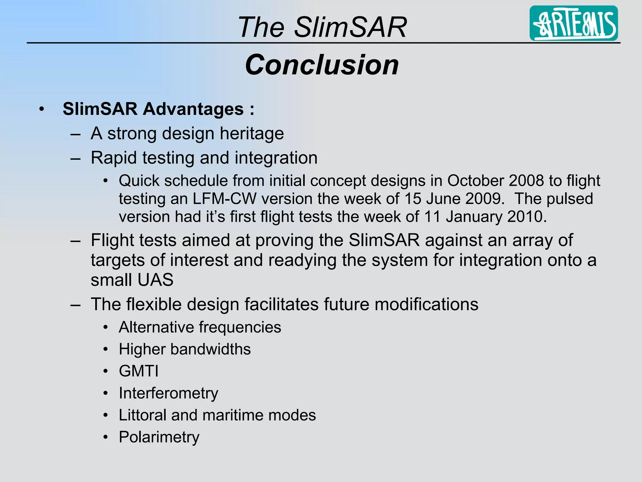
2) It was designed based on existing SAR systems like MicroASAR and NuSAR to take advantage of proven technologies and allow for rapid testing and integration.
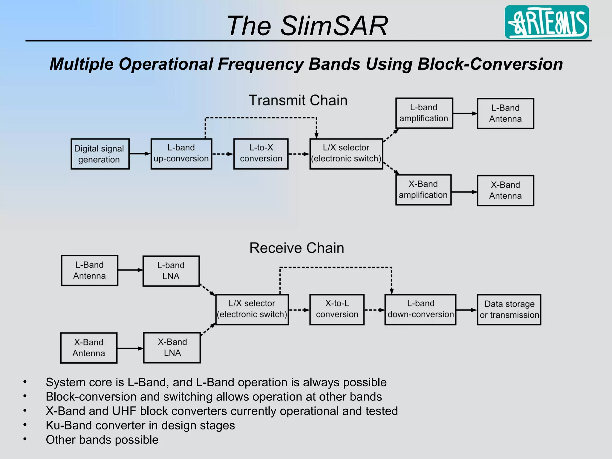
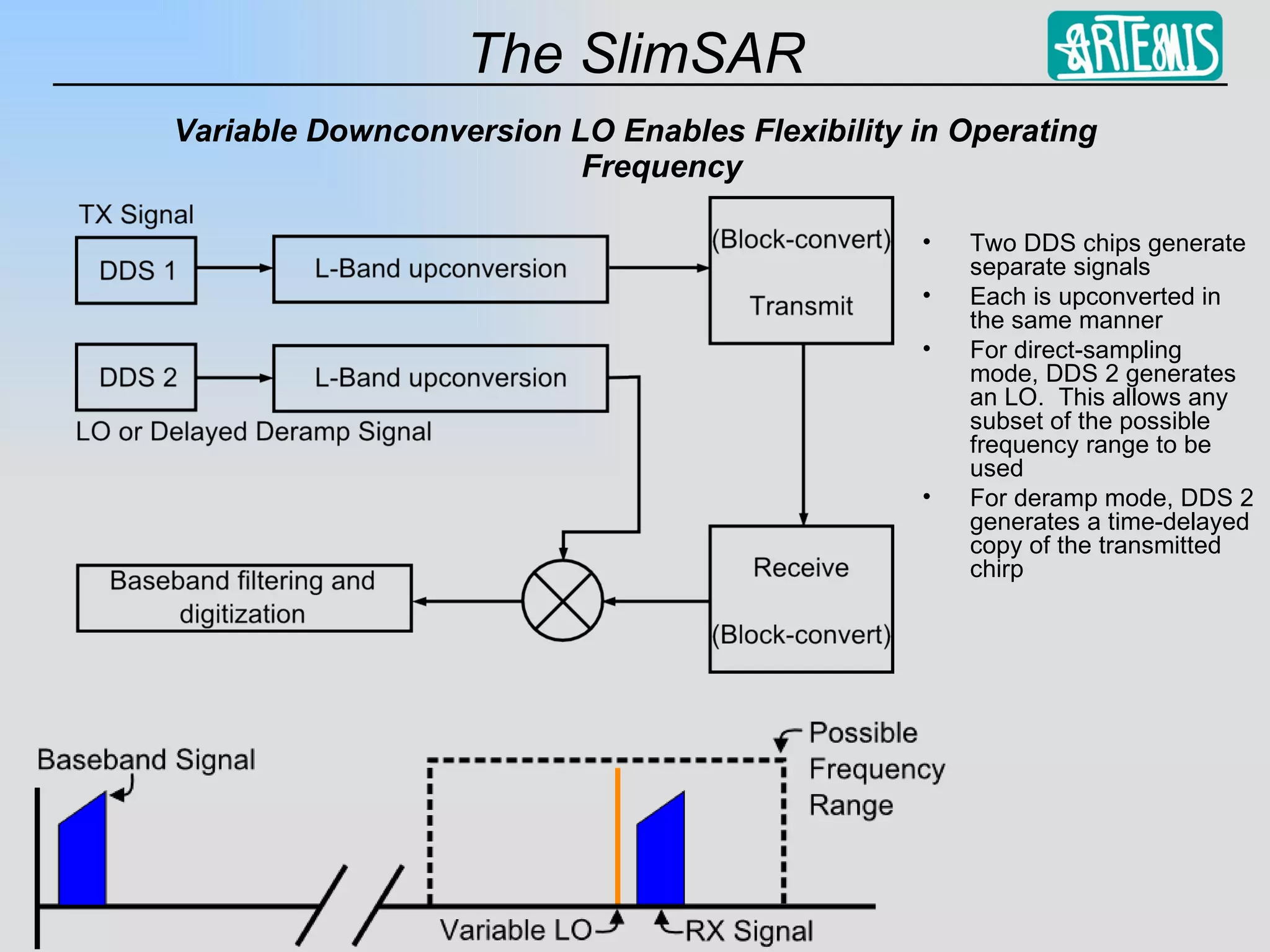
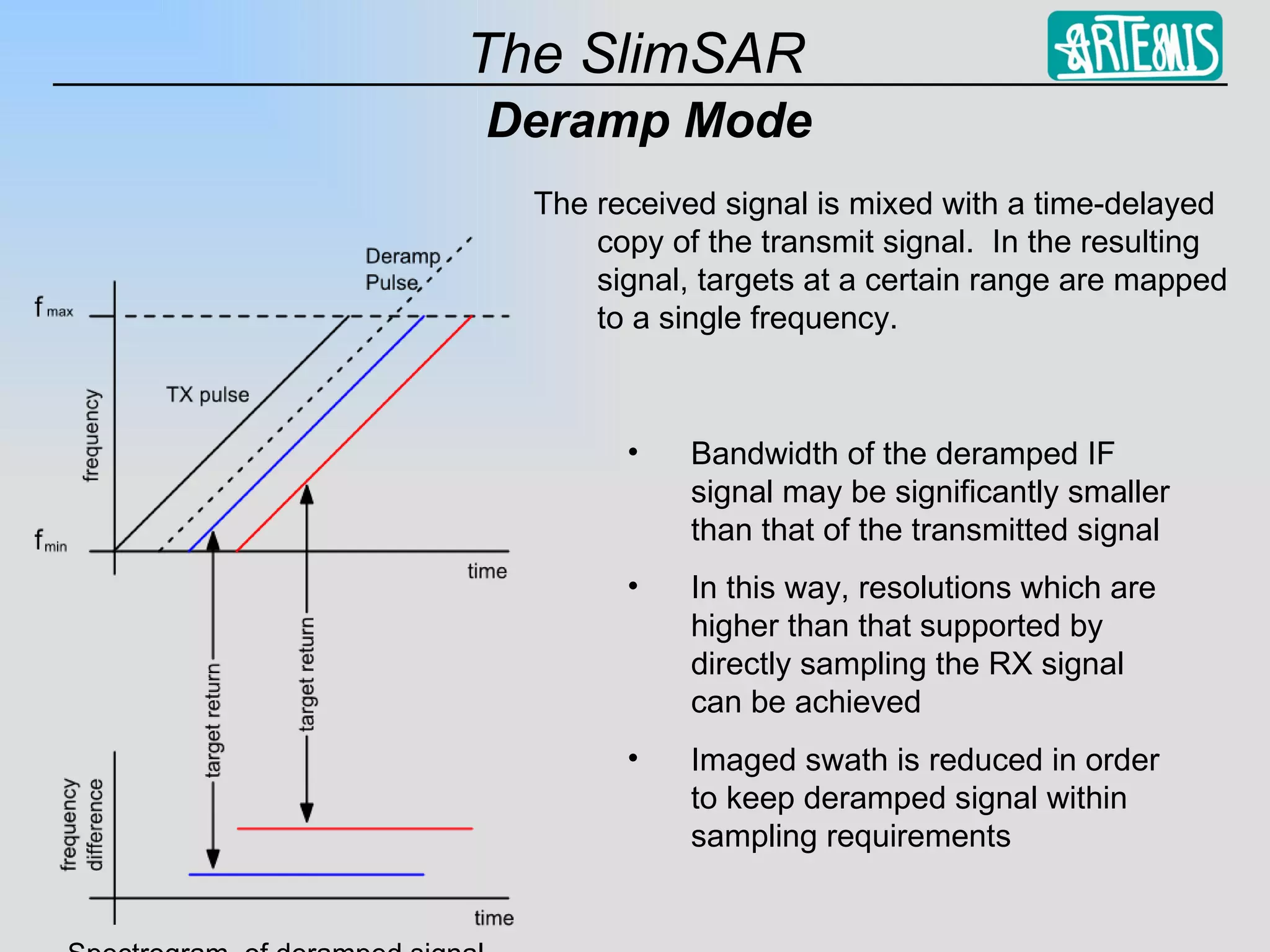
3) The system uses a block upconversion design that allows it to operate at different frequency bands and in direct sampling or deramp modes, providing flexibility.