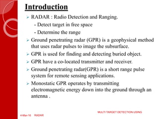
HIGH PERFORMANCE CONCRETE
SDM COLLEGE OF ENGINEERING AND
TECHNOLOGY, DHARWAD
CIVIL ENGINEERING DEPT.
Presented by
Name-MANMOHAN KUMAR
USN-2SD12EC040
UNDER THE GUIDENCE OF
Mr. C.P.JOSHI (Asst. Prof.)
6
Contents
 Introduction
 Components of GPR
 GPR working principle
 Data Acquisition
 GPR Technology
 Data Model and Layer-Stripping Inversion
 D/T in pavement profiling
 Multiple-Interface D/T
 Applications
 Advantages
 Limitations
 Conclusion
4-Mar-16 MULTI TARGET DETECTIONRADAR
Introduction
 RADAR : Radio Detection and Ranging.
- Detect target in free space
- Determine the range
 Ground penetrating radar (GPR) is a geophysical method
that uses radar pulses to image the subsurface.
 GPR is used for finding and detecting buried object.
 GPR have a co-located transmitter and receiver.
 Ground penetrating radar(GPR) is a short range pulse
system for remote sensing applications.
 Monostatic GPR operates by transmitting
electromagnetic energy down into the ground through an
antenna .
4-Mar-16
MULTI TARGET DETECTION USING
RADAR
Components of GPR
4-Mar-16
MULTI TARGET DETECTION USING
RADAR
1.Transmitting and receiving unit
2.Control unit
3.Display unit
4.Power supplies
Fig no.:-01, Process of GPR[1]
3/4/2016 MULTI TARGET DETECTIONRADAR
Antennae Frequency Maximum Penetration
Depth
Examples of Potential
Use
1500 MHz 0.5 m Rebar mapping and
concrete evaluation.
900 MHz 1 m
Pipe and void detection
or assessing concrete
thickness.
400 MHz 4 m
Utility surveys,
pavement evaluation,
storage tank detection
and assessing structural
integrity.
300 MHz 6m Utility surveys, geology
and archaeology.
GPR Working Principle
4-Mar-16
MULTI TARGET DETECTION USING
RADAR
Fig no.:-02,GPR working principle
[2]
Reflected Signal:
 The amount of
reflected energy at an
interface is governed
by:
where ρ1,2 is the
reflection coefficient
and εr1 and εr2 are the
dielectric constants.
21
21
2,1
rr
rr






Typical Dielectric Constants:
Material Relative
permittivity
Air 1
Asphalt: dry 2-4
Clay 2-40
Dry sand 3-5
Concrete: dry 4-10
Fresh water 80
Metals ∞
GPR Depth Determination:
 The reflected signal
has information on:
◦ how quickly
the signal traveled
◦ how much was
attenuated
 These quantities
depend on spatial
configuration and
materials.
The depth of a layer is given
by:
D = (5.9t)/sqrt.
of(Er)
D = depth of target (inch.)
t = wave travel time (nanosecond)
5.9 = a constant incorporating speed
of light and unit conversions
Er = dielectric constant of
subsurface material
Data Acquisition
4-Mar-16
MULTI TARGET DETECTION USING
RADAR
GPR uses high frequency radio waves and transmits
into the ground.
When the waves hits the buried object or a boundary
with different dielectric constants, the receiving antenna
records variations in the reflected return signal.
The depth range of GPR is limited by electrical
conductivity of the ground ,the transmitted frequency and
the radiated power.
 As conductivity increases the penetration depth
decreases.
4-Mar-16
MULTI TARGET DETECTION USING
RADAR
Fig no.:-03,schematic diagram of a GPR
[3]
GPR Technology
4-Mar-16
MULTI TARGET DETECTION USING
RADAR
Fig no.:-04 ,GPR technology [4]
GPR Technology(cont.)
4-Mar-16
MULTI TARGET DETECTION USING
RADAR
Air coupled antenna.
Ground coupled antenna.
Fig no.:-05,Air coupled antenna[5] Fig no.:-06,Ground coupled
antenna[6]
Data Model and Layer-Stripping
Inversion
 In pavement, each layer of asphalt or concrete is basically
a mixture of particles embedded in an homogenous
matrix.
 Since particle size is considered to be small if compared
to the waveform resolution of the GPR system, each
system can be model as a homogeneous medium with
effective complex dielectric permittivity values.
 Layer-stripping inversion is used to estimate the
permittivity profile as well as the location in depth of
those interfaces estimated in time.
4-Mar-16
MULTI TARGET DETECTION USING
RADAR
Detection/Tracking in pavement
profiling
 Layer-stripping inversion with monostatic GPR is rather
complicated since the echo amplitude decreases with
time due to waveform attenuation.
 Moreover ,the estimate of the echo amplitude is biased
due to propagation through random media.
 Consequently, in pavement profiling, the SNR decreases
with depth.
4-Mar-16
MULTI TARGET DETECTION USING
RADAR
Multiple-Interface D/T
 In the presence of more than one interface, the
multimode and the D/T components tracks the echo
delay with the largest SNR.
 In principle, this tracking ambiguity could be avoided by
processing subsequence of time samples.
 In practice, errors are difficult to avoid when two
interfaces are close to each other (because of limits in
echo resolution), when one interface splits into two
interfaces, or even when two or more interfaces merge
into one.
4-Mar-16
MULTI TARGET DETECTION USING
RADAR
Application
4-Mar-16
MULTI TARGET DETECTION USING
RADAR
 In the Earth sciences it is used to study bedrock, soils,
groundwater and ice.
 Military uses including detection of mines, unexploded
ordnance detection, and tunnels.
 Locating clandestine graves and buried evidence.
 The other main applications is to locate underground
utilities.
Advantages
4-Mar-16
MULTI TARGET DETECTION USING
RADAR
 Low cost
 Extremely accurate
 Fast
 Not needed to drilling and digging selected area
 Real time targeting
 Non-destructive
 Digital media storage
 Easy to operate
 Safe
 Site specifics.
 Limitations if dielectric properties are similar.
 Difficult in thin layer.
 Compromise between penetration depths and target
resolutions.
 Requires fairly uniform soil for moisture estimation.
4-Mar-16
MULTI TARGET DETECTION USING
RADAR
Limitations
References
1. D. J. Daniels, D. J. Gunton, and H. F. Scott,
“Introduction to subsurface radar,” Proc. Inst. Elect.
Eng. F, vol. 135, pp. 278–320, Aug. 1988.
2. U. Spagnolini, “Permittivity measurements of
multilayered media with monostatic pulse radar,” IEEE
Trans. Geosci. Remote Sensing, vol. 35, pp. 454–463,
Mar. 1997.
3. S. S. Blackman, Multiple-Target Tracking with Radar
Applications. Dedham, MA: Artech House, 1986.
4. http://Wikipedia.com/
5. http://books.google.com/
4-Mar-16
MULTI TARGET DETECTION USING
RADAR
Thank
YOU
4-Mar-16 MULTI TARGET DETECTION USING RADAR

GROUND PENETRATING RADAR(GPR) ppt

  • 1.
    HIGH PERFORMANCE CONCRETE SDMCOLLEGE OF ENGINEERING AND TECHNOLOGY, DHARWAD CIVIL ENGINEERING DEPT. Presented by Name-MANMOHAN KUMAR USN-2SD12EC040 UNDER THE GUIDENCE OF Mr. C.P.JOSHI (Asst. Prof.) 6
  • 2.
    Contents  Introduction  Componentsof GPR  GPR working principle  Data Acquisition  GPR Technology  Data Model and Layer-Stripping Inversion  D/T in pavement profiling  Multiple-Interface D/T  Applications  Advantages  Limitations  Conclusion 4-Mar-16 MULTI TARGET DETECTIONRADAR
  • 3.
    Introduction  RADAR :Radio Detection and Ranging. - Detect target in free space - Determine the range  Ground penetrating radar (GPR) is a geophysical method that uses radar pulses to image the subsurface.  GPR is used for finding and detecting buried object.  GPR have a co-located transmitter and receiver.  Ground penetrating radar(GPR) is a short range pulse system for remote sensing applications.  Monostatic GPR operates by transmitting electromagnetic energy down into the ground through an antenna . 4-Mar-16 MULTI TARGET DETECTION USING RADAR
  • 4.
    Components of GPR 4-Mar-16 MULTITARGET DETECTION USING RADAR 1.Transmitting and receiving unit 2.Control unit 3.Display unit 4.Power supplies Fig no.:-01, Process of GPR[1]
  • 5.
    3/4/2016 MULTI TARGETDETECTIONRADAR Antennae Frequency Maximum Penetration Depth Examples of Potential Use 1500 MHz 0.5 m Rebar mapping and concrete evaluation. 900 MHz 1 m Pipe and void detection or assessing concrete thickness. 400 MHz 4 m Utility surveys, pavement evaluation, storage tank detection and assessing structural integrity. 300 MHz 6m Utility surveys, geology and archaeology.
  • 6.
    GPR Working Principle 4-Mar-16 MULTITARGET DETECTION USING RADAR Fig no.:-02,GPR working principle [2]
  • 7.
    Reflected Signal:  Theamount of reflected energy at an interface is governed by: where ρ1,2 is the reflection coefficient and εr1 and εr2 are the dielectric constants. 21 21 2,1 rr rr       Typical Dielectric Constants: Material Relative permittivity Air 1 Asphalt: dry 2-4 Clay 2-40 Dry sand 3-5 Concrete: dry 4-10 Fresh water 80 Metals ∞
  • 8.
    GPR Depth Determination: The reflected signal has information on: ◦ how quickly the signal traveled ◦ how much was attenuated  These quantities depend on spatial configuration and materials. The depth of a layer is given by: D = (5.9t)/sqrt. of(Er) D = depth of target (inch.) t = wave travel time (nanosecond) 5.9 = a constant incorporating speed of light and unit conversions Er = dielectric constant of subsurface material
  • 9.
    Data Acquisition 4-Mar-16 MULTI TARGETDETECTION USING RADAR GPR uses high frequency radio waves and transmits into the ground. When the waves hits the buried object or a boundary with different dielectric constants, the receiving antenna records variations in the reflected return signal. The depth range of GPR is limited by electrical conductivity of the ground ,the transmitted frequency and the radiated power.  As conductivity increases the penetration depth decreases.
  • 10.
    4-Mar-16 MULTI TARGET DETECTIONUSING RADAR Fig no.:-03,schematic diagram of a GPR [3]
  • 11.
    GPR Technology 4-Mar-16 MULTI TARGETDETECTION USING RADAR Fig no.:-04 ,GPR technology [4]
  • 12.
    GPR Technology(cont.) 4-Mar-16 MULTI TARGETDETECTION USING RADAR Air coupled antenna. Ground coupled antenna. Fig no.:-05,Air coupled antenna[5] Fig no.:-06,Ground coupled antenna[6]
  • 13.
    Data Model andLayer-Stripping Inversion  In pavement, each layer of asphalt or concrete is basically a mixture of particles embedded in an homogenous matrix.  Since particle size is considered to be small if compared to the waveform resolution of the GPR system, each system can be model as a homogeneous medium with effective complex dielectric permittivity values.  Layer-stripping inversion is used to estimate the permittivity profile as well as the location in depth of those interfaces estimated in time. 4-Mar-16 MULTI TARGET DETECTION USING RADAR
  • 14.
    Detection/Tracking in pavement profiling Layer-stripping inversion with monostatic GPR is rather complicated since the echo amplitude decreases with time due to waveform attenuation.  Moreover ,the estimate of the echo amplitude is biased due to propagation through random media.  Consequently, in pavement profiling, the SNR decreases with depth. 4-Mar-16 MULTI TARGET DETECTION USING RADAR
  • 15.
    Multiple-Interface D/T  Inthe presence of more than one interface, the multimode and the D/T components tracks the echo delay with the largest SNR.  In principle, this tracking ambiguity could be avoided by processing subsequence of time samples.  In practice, errors are difficult to avoid when two interfaces are close to each other (because of limits in echo resolution), when one interface splits into two interfaces, or even when two or more interfaces merge into one. 4-Mar-16 MULTI TARGET DETECTION USING RADAR
  • 16.
    Application 4-Mar-16 MULTI TARGET DETECTIONUSING RADAR  In the Earth sciences it is used to study bedrock, soils, groundwater and ice.  Military uses including detection of mines, unexploded ordnance detection, and tunnels.  Locating clandestine graves and buried evidence.  The other main applications is to locate underground utilities.
  • 17.
    Advantages 4-Mar-16 MULTI TARGET DETECTIONUSING RADAR  Low cost  Extremely accurate  Fast  Not needed to drilling and digging selected area  Real time targeting  Non-destructive  Digital media storage  Easy to operate  Safe
  • 18.
     Site specifics. Limitations if dielectric properties are similar.  Difficult in thin layer.  Compromise between penetration depths and target resolutions.  Requires fairly uniform soil for moisture estimation. 4-Mar-16 MULTI TARGET DETECTION USING RADAR Limitations
  • 19.
    References 1. D. J.Daniels, D. J. Gunton, and H. F. Scott, “Introduction to subsurface radar,” Proc. Inst. Elect. Eng. F, vol. 135, pp. 278–320, Aug. 1988. 2. U. Spagnolini, “Permittivity measurements of multilayered media with monostatic pulse radar,” IEEE Trans. Geosci. Remote Sensing, vol. 35, pp. 454–463, Mar. 1997. 3. S. S. Blackman, Multiple-Target Tracking with Radar Applications. Dedham, MA: Artech House, 1986. 4. http://Wikipedia.com/ 5. http://books.google.com/ 4-Mar-16 MULTI TARGET DETECTION USING RADAR
  • 20.
    Thank YOU 4-Mar-16 MULTI TARGETDETECTION USING RADAR