The document discusses underground utility detection and locating buried pipes and cables. It covers several key topics:
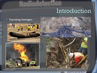
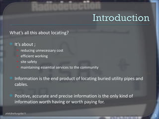
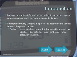
- The importance of safety when digging and how locating utilities helps avoid damage
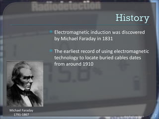
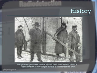
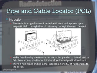
- Common utility detection techniques like electromagnetic induction, ground penetrating radar, and cable locators
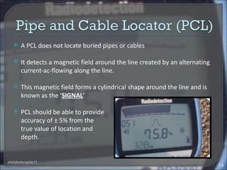
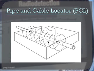
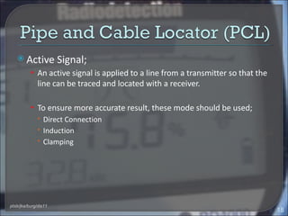
- How cable locators work to detect active and passive signals around buried lines
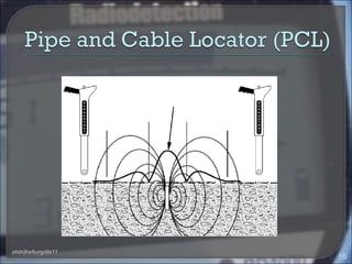
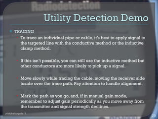
- Processes for sweeping an area and tracing individual utilities using cable locators
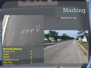
- Standards and guidelines for underground utility mapping in Malaysia