This document discusses thermoelectric cooling and is prepared by Mayank H. Pal for a project. It contains information on:
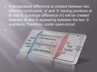
1. Thermoelectric cooling provides an alternative solution to compressor-based coolers by using the Seebeck effect where a voltage is generated by certain materials in a temperature gradient.
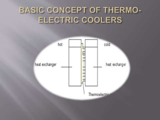
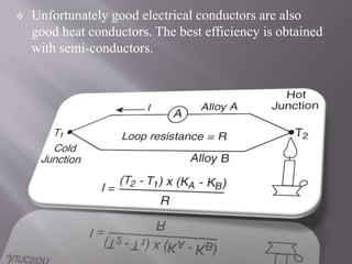
2. The basic principles are the Peltier effect where heat is absorbed or released at a junction when an electric current passes between two dissimilar conductors, and using semiconductors with high electrical and low thermal conductivity.
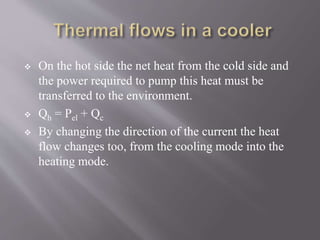
3. Thermoelectric coolers have advantages of small size, light weight, no fluids, precise temperature control, and can be used for heating by reversing current direction.