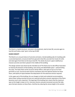
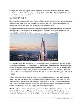
The document provides information about the Shard, the tallest building in the UK. It discusses its construction, which involved a steel structure up to level 40, then a post-tensioned concrete frame up to level 69, topped by a steel-framed spire. Modular construction techniques were used to minimize risks during assembly of the steelwork sections. The building employs various energy efficient technologies and materials to reduce its environmental impact.
![B u i l d i n g S c i e n c e | 9
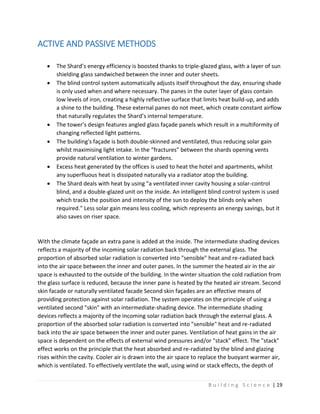
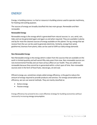
Making connections
Where bolted connections couldn’t be avoided, the architect
worked with the steelwork contractor to dress the
connections with cover plates. For example, on the
connection between the vertical, horizontal and diagonal
bracing Severfield-Reeve produced curved plates.
Other connections were dressed with filler after erection,
and over-coating such as those on the wing walls, which have
flush welds or hidden connections.
The spire has a steel stair supported by a steel core structure
built in three-storey units. The stair extends from floor 67 to
87. It wraps around the central core and is tied to the
structure at landings on every third floor.
First the stair tower was installed then the landings were
hoisted into place. It was installed complete with aluminium treads, handrails and flooring to
minimise the number of trades needed after the spire’s installation. The stair core structure
alone weighs 100 tonnes and consists of 110 pieces.
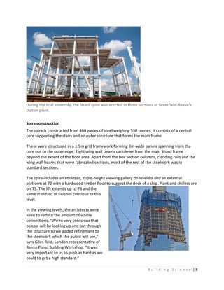
Trial assembly
The stair structure was pre-assembled in Sherburn near Scarborough by Severfield-Rowen’s
subsidiary company Atlas Ward Structures — Light Steel Division. The spire main structure was
trial erected in three sections at Severfield-Reeve’s Dalton plant in North Yorkshire.
“During [trial] assembly we made sure that we put every piece of steel, handrail and mesh into
place so that we knew it would fit,” says Severfield-Reeve contracts manager Doug Willis.
The very last pieces of steelwork to be installed will be the cantilevered tips. Above level 87 the
three highest tips — Shards 1, 6 and 14 — will be lifted, bolted into place and glazed. These are
fabricated, vertical trusses joined together to create a 3D frame that holds the glass tip of the
shard up. The largest one is a box truss 10.4m long, reaching up some 18.2m above level 87.
All spire steel is finished in a high-quality corrosion protection system of three layers topped by
a glass flake product for added durability — a specification similar to that used for extreme
conditions such as on the Forth Road Bridge.
Mace had built in an allowance for temporary works once the spire was installed on the Shard
but this wasn’t needed — each piece was within 5mm of what was expected. “From my point of
view the spire has taken the incorporation of safety planning, design, production and
installation of steelwork to a new and advanced level,” says Mace’s Adrian Thomson.](https://image.slidesharecdn.com/theshard-161225151149/85/The-Shard-9-320.jpg)
![B u i l d i n g S c i e n c e | 18
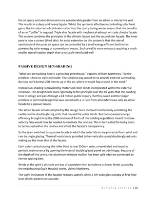
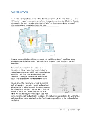
ENERGY EFFICIENCY
Mindful of the Shard’s environmental impact and in order to maintain the highest levels of
energy efficiency, the building is fitted with a natural gas-fuelled combined heat & power plant.
The Shard utilises a GE Jenbacher JMS416GS-NL gas engine and the cogeneration facility was
engineered, installed and will be maintained by Clarke Energy.
This combined heat and power (CHP) plant will provide both 1.131MW of electricity and
1.199MW of hot water at high efficiency (85.3% total, 41.4% electrical) to the surrounding area.
This helps to reduce carbon emissions and contributes to the low-carbon footprint of the
building. In parallel this provides significant cost savings versus the separate purchase of
electricity and gas from the national grids. The generators are located in the basement of the
building and are housed in acoustic enclosures in order to negate the emission of sound from
the engines. The gas engines are also characterised by very low levels of NOx emissions
(<250mg/Nm3) which is important to achieve the strict air quality requirements in the capital.
Of the steel that was used in construction, 20% was recycled, while 95% of the waste produced
during construction was recycled as well. Also, sky gardens on each floor promote natural
ventilation and improve air quality.
The Shard's extensive use of energy-saving materials and techniques contributes to the building
using 30% less energy than other high-rises of comparable dimensions.
For structural reasons, the emphasis in the design of a tall building is to reduce weight, and so
the Shard is a lightweight building in terms of its ability to store heat. Buildings that have heavy
concrete walls and slabs [think Empire State Building again] are able to store heat in their
structure."
95% of construction materials recycled
20% of all steelwork from recycled sources
Combined heat and power creates efficiencies across the whole site saving 10% CO2
annually
Triple skin intelligent façade minimising the effects of solar gain, whilst allowing
maximum use of natural light
Winters gardens providing naturally ventilated workspaces
Mainline rail, tube and bus hub integrated into the development vastly reducing
secondary journeys
A plot ratio of 32.1% ensuring land is used efficiently](https://image.slidesharecdn.com/theshard-161225151149/85/The-Shard-18-320.jpg)