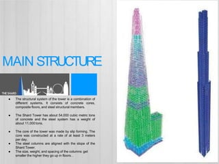
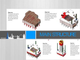
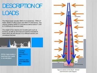
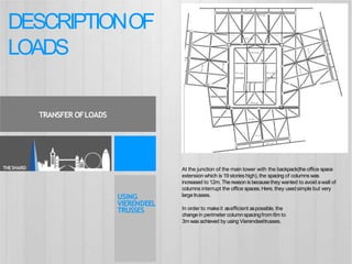
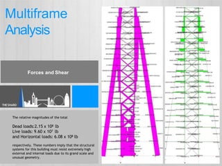
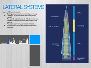
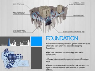
TheShardat LondonBridge
Structure Case Study by:
KRITHIKA.N
INTRODUCTION
Client: Teighmore Ltd c/o SellarProperty Group
Location: London
ProjectYear: 2009- 2012
ProjectArea: 1,200,000sqft
Height: 1,016ft (310m)
ProjectCosts: £435Million
LeadArchitect: RenzoPianoBuilding Workshop &
AdamsonAssociates
StructuralEngineer: WSPCantorSeinuk
THESHARD
DESIGNCONCEPT
THESHARD
Thegoal for the design was to accentuatethe urbanand createastructure that would
blend with theskyline.
Locatedin the center of atransportationhub, TheShard’s aimsto sympathize
with urbanscape.
Sincethe schematicdesign process, geographic conditionswere
designedfor.
Residential
62,000 sq ft
Hotel
192,000 sq ft
Offices
594,000 sqft
Retail
61,000 sqft
Restaurant
Offices
THESHARD
Hotel
Spire
Viewing Gallery
Apartment
PROJECTREQUIREMENTS
8,000
44
48
Gross InternalArea
Area of Facade
Population
Lifts
Car ParkingSpaces
1,367,000 sq ft
600,000 sq ft
580,000 sqft
11,000 tons
Volume ofConcrete
Weight of Steel
Glass Panels 11,000
THESHARD
● The structural system of the tower is a combination of
different systems. It consists of concrete cores,
composite floors, and steel structural members.
● The Shard Tower has about 54,000 cubic metric tons
of concrete and the steel system has a weight of
about 11,000 tons.
● The core of the tower was made by slip forming. The
core was constructed at a rate of at least 3 meters
per day.
● The steel columns are aligned with the slope of the
Shard Tower.
● The size, weight, and spacing of the columns get
smaller the higher they go up in floors. .
MAIN STRUCTURE
THESHARD
MAIN STRUCTURE
THESHARD
•The floor framing in the Shardwas altered with height; the
office levels were designed in steel, while the hotel and
residences were framed in concrete. Thetransition did not
exactly match the changeof use; steel construction was
continued up to level 40- sixfloors above lowest part of hotel.
•Thereason for this mismatch was related to the span between
perimeter columns and the low allowable deflections of the glass
façade.
•Thecomposite edgebeamsachieved the required
performance with aspan of 6 but in the concrete levels, the
maximum perimeter columnspacingwas 3m becausedown-
stand beamswere notpreferred.
•Transfer structures were needed in order to achieve the
reduction in spacing,and thesetook the form of three-storey
high vierendeel frames at the top of the steellevels (i.e. from
level 37 to level40).
.
COMPONENTS
Steel FloorSandwich
ConcreteFloorSandwich
Floors
THESHARD
“The Spire”
•The‘Spire’ is the 60m tall pinnacleat top of the tower, containing
the public viewinggallery.
• Theconcrete core stops at level 72 and continues asasteel mast.
• The solid floors are replaced by open grids and the shardsstop at
different levels.
•The spire comprises acentral steelmast to provide stability, floor
platesevery third level and the ‘shards’ themselves.
•Theshardsextend past the top floor plate by up to 18 m and are
supported by cantileveringtrusses.
• Thecompressionbooms are restrained by U-frame actionfrom
the trussesacting together with the framesin the plane of the
facade.
•The wind tunnel test on the spire checkedthe structure for any
resonantor ‘galloping’ effects from wind gusts.
.
TheSpire
COMPONENTS
● Where bolted connections couldn’t be avoided, the architect worked
with the steelwork contractor to dress the connections with cover
plates. For example, on the connection between the vertical,
horizontal and diagonal bracing Severfield-Reeve produced curved
plates.
● Other connections were dressed with filler after erection, and over-
coating such as those on the wing walls, which have flush welds or
CONNECTIONS
THESHARD
Loadfrom
concrete
part=12701.41
kips
Loadfrom steel
parts=2486.9005
kips
The Shard tower includes 5800 m2 of residential, 17800 m2
Hotel, 55200 m2 office space and 5600 m2 retail stores. This
volume contains 54000 m3 concrete as well as about11,000
to 12,500tons of structural steel.
The weight of live objects and movable parts such as
furniture, as well as wind load and seismic load(lateral
loads which we will discuss it in a different section) are
considered live load.
All this masscreates a
deadload that needs
to becalculated.
THESHARD
DESCRIPTIONOF
LOADS
In order to makeit asefficient aspossible, the
changein perimeter columnspacingfrom 6m to
3m was achieved by using Vierendeeltrusses.
USING
VIERENDEEL
TRUSSES
At the junction of the main tower with the backpack(the office space
extension which is 19 stories high), the spacing of columns was
increased to 12m. The reason is becausethey wanted to avoid awall of
columns interrupt the office spaces.Here, they usedsimple but very
largetrusses.
DESCRIPTIONOF
LOADS
THESHARD
TRANSFER OFLOADS
COLUMNS
Theychosecranked,y shapedperimeter columnsat
first, but thenchangedtheir
decision to the simplicityof direct line. Because it was
better both aesthetically andeconomically.
THESHARD
Loading the columns at ground level
DESCRIPTIONOFLOADS
The relative magnitudes of the total
Dead loads:2.15 x 10⁸ lb
Live loads: 9.60 x 10⁷ lb
and Horizontal loads: 6.08 x 10⁸ lb
respectively. These numbers imply that the structural
systems for this building must resist extremely high
external and internal loads due to its grand scale and
unusual geometry.
THESHARD
Multiframe
Analysis
Forces and Shear
Moment and Deflection
THESHARD
Multiframe
Analysis
The relative magnitudes of the total
Dead loads:2.15 x 10⁸ lb
Live loads: 9.60 x 10⁷ lb
and Horizontal loads: 6.08 x 10⁸ lb
respectively. These numbers imply that the structural
systems for this building must resist extremely high
external and internal loads due to its grand scale and
unusual geometry.
● Buildingis composedof four material layersvertically.
● Layeringof structural materialsgivestability where
needed.
● Theconcrete section from levels 41 to 69 providesmass
dampers to minimize oscillations and stiffness to the
building.
● Aconcrete core running provides lateralstability.
● Provides vertical rigidity and allows for minimalfloor
platesshift.
LATERALSYSTEMS
Layering of StructuralMaterials
THESHARD
• London hasageologytypical soil at this area.
• Thewater table is at the top of the gravel.
•Tectonic plate under neath ground layers effect wasto
makethe eastern piles afew metres deeper.
SOILANALYSIS
THESHARD
Description
•Movement monitoring, vibration, ground water and reuse
of old piles were taken into account in designing
foundation.
•Top-Down construction methodology wasusedin
construction.
• Plunged columns usedto supported core andTop-down
slabs.
•Theslab underneath the core has3m thicknesswith four
layers of reinforcement in eachdirection to provide
stiffness.
FOUNDATION
THESHARD
•Theground slab wascaston aslip membrane so
that blinding concrete did not adhere to the
underside.
• Excavation of two levels of basement then took
placebeneath the ground floor slab.
•Meanwhile, the slab for level B2wascast.
Excavation continued beneath B2to formation
level.
•Theslipform wasnot allowed to climb above level
21 while the core wassupported on plunge
columns only.
•Theraft slab wasinstalled in asingle5500m3
pour taking 32 hours. Up to this point, all loads
were carried on the secantwall and the piles
containing plunge columns.
EXCAVATION
THESHARD

Shard tower

  • 1.
  • 2.
    INTRODUCTION Client: Teighmore Ltdc/o SellarProperty Group Location: London ProjectYear: 2009- 2012 ProjectArea: 1,200,000sqft Height: 1,016ft (310m) ProjectCosts: £435Million LeadArchitect: RenzoPianoBuilding Workshop & AdamsonAssociates StructuralEngineer: WSPCantorSeinuk THESHARD
  • 5.
    DESIGNCONCEPT THESHARD Thegoal for thedesign was to accentuatethe urbanand createastructure that would blend with theskyline. Locatedin the center of atransportationhub, TheShard’s aimsto sympathize with urbanscape. Sincethe schematicdesign process, geographic conditionswere designedfor.
  • 6.
    Residential 62,000 sq ft Hotel 192,000sq ft Offices 594,000 sqft Retail 61,000 sqft Restaurant Offices THESHARD Hotel Spire Viewing Gallery Apartment PROJECTREQUIREMENTS 8,000 44 48 Gross InternalArea Area of Facade Population Lifts Car ParkingSpaces 1,367,000 sq ft 600,000 sq ft 580,000 sqft 11,000 tons Volume ofConcrete Weight of Steel Glass Panels 11,000
  • 7.
    THESHARD ● The structuralsystem of the tower is a combination of different systems. It consists of concrete cores, composite floors, and steel structural members. ● The Shard Tower has about 54,000 cubic metric tons of concrete and the steel system has a weight of about 11,000 tons. ● The core of the tower was made by slip forming. The core was constructed at a rate of at least 3 meters per day. ● The steel columns are aligned with the slope of the Shard Tower. ● The size, weight, and spacing of the columns get smaller the higher they go up in floors. . MAIN STRUCTURE
  • 8.
  • 9.
    THESHARD •The floor framingin the Shardwas altered with height; the office levels were designed in steel, while the hotel and residences were framed in concrete. Thetransition did not exactly match the changeof use; steel construction was continued up to level 40- sixfloors above lowest part of hotel. •Thereason for this mismatch was related to the span between perimeter columns and the low allowable deflections of the glass façade. •Thecomposite edgebeamsachieved the required performance with aspan of 6 but in the concrete levels, the maximum perimeter columnspacingwas 3m becausedown- stand beamswere notpreferred. •Transfer structures were needed in order to achieve the reduction in spacing,and thesetook the form of three-storey high vierendeel frames at the top of the steellevels (i.e. from level 37 to level40). . COMPONENTS Steel FloorSandwich ConcreteFloorSandwich Floors
  • 10.
    THESHARD “The Spire” •The‘Spire’ isthe 60m tall pinnacleat top of the tower, containing the public viewinggallery. • Theconcrete core stops at level 72 and continues asasteel mast. • The solid floors are replaced by open grids and the shardsstop at different levels. •The spire comprises acentral steelmast to provide stability, floor platesevery third level and the ‘shards’ themselves. •Theshardsextend past the top floor plate by up to 18 m and are supported by cantileveringtrusses. • Thecompressionbooms are restrained by U-frame actionfrom the trussesacting together with the framesin the plane of the facade. •The wind tunnel test on the spire checkedthe structure for any resonantor ‘galloping’ effects from wind gusts. . TheSpire COMPONENTS
  • 11.
    ● Where boltedconnections couldn’t be avoided, the architect worked with the steelwork contractor to dress the connections with cover plates. For example, on the connection between the vertical, horizontal and diagonal bracing Severfield-Reeve produced curved plates. ● Other connections were dressed with filler after erection, and over- coating such as those on the wing walls, which have flush welds or CONNECTIONS THESHARD
  • 12.
    Loadfrom concrete part=12701.41 kips Loadfrom steel parts=2486.9005 kips The Shardtower includes 5800 m2 of residential, 17800 m2 Hotel, 55200 m2 office space and 5600 m2 retail stores. This volume contains 54000 m3 concrete as well as about11,000 to 12,500tons of structural steel. The weight of live objects and movable parts such as furniture, as well as wind load and seismic load(lateral loads which we will discuss it in a different section) are considered live load. All this masscreates a deadload that needs to becalculated. THESHARD DESCRIPTIONOF LOADS
  • 13.
    In order tomakeit asefficient aspossible, the changein perimeter columnspacingfrom 6m to 3m was achieved by using Vierendeeltrusses. USING VIERENDEEL TRUSSES At the junction of the main tower with the backpack(the office space extension which is 19 stories high), the spacing of columns was increased to 12m. The reason is becausethey wanted to avoid awall of columns interrupt the office spaces.Here, they usedsimple but very largetrusses. DESCRIPTIONOF LOADS THESHARD TRANSFER OFLOADS
  • 14.
    COLUMNS Theychosecranked,y shapedperimeter columnsat first,but thenchangedtheir decision to the simplicityof direct line. Because it was better both aesthetically andeconomically. THESHARD Loading the columns at ground level DESCRIPTIONOFLOADS
  • 15.
    The relative magnitudesof the total Dead loads:2.15 x 10⁸ lb Live loads: 9.60 x 10⁷ lb and Horizontal loads: 6.08 x 10⁸ lb respectively. These numbers imply that the structural systems for this building must resist extremely high external and internal loads due to its grand scale and unusual geometry. THESHARD Multiframe Analysis Forces and Shear
  • 16.
    Moment and Deflection THESHARD Multiframe Analysis Therelative magnitudes of the total Dead loads:2.15 x 10⁸ lb Live loads: 9.60 x 10⁷ lb and Horizontal loads: 6.08 x 10⁸ lb respectively. These numbers imply that the structural systems for this building must resist extremely high external and internal loads due to its grand scale and unusual geometry.
  • 17.
    ● Buildingis composedoffour material layersvertically. ● Layeringof structural materialsgivestability where needed. ● Theconcrete section from levels 41 to 69 providesmass dampers to minimize oscillations and stiffness to the building. ● Aconcrete core running provides lateralstability. ● Provides vertical rigidity and allows for minimalfloor platesshift. LATERALSYSTEMS Layering of StructuralMaterials THESHARD
  • 18.
    • London hasageologytypicalsoil at this area. • Thewater table is at the top of the gravel. •Tectonic plate under neath ground layers effect wasto makethe eastern piles afew metres deeper. SOILANALYSIS THESHARD Description
  • 19.
    •Movement monitoring, vibration,ground water and reuse of old piles were taken into account in designing foundation. •Top-Down construction methodology wasusedin construction. • Plunged columns usedto supported core andTop-down slabs. •Theslab underneath the core has3m thicknesswith four layers of reinforcement in eachdirection to provide stiffness. FOUNDATION THESHARD
  • 20.
    •Theground slab wascastonaslip membrane so that blinding concrete did not adhere to the underside. • Excavation of two levels of basement then took placebeneath the ground floor slab. •Meanwhile, the slab for level B2wascast. Excavation continued beneath B2to formation level. •Theslipform wasnot allowed to climb above level 21 while the core wassupported on plunge columns only. •Theraft slab wasinstalled in asingle5500m3 pour taking 32 hours. Up to this point, all loads were carried on the secantwall and the piles containing plunge columns. EXCAVATION THESHARD