We live in the 21. century, we drive cars, we have the thermal and nuclear power plants and it all started with the work of Carnot, who established the principle of creating work of en engine from the supplied warmth. However, we have also problems with the pollution of our environment and the created warmth from these technical devices
ABSTRACT: We live in the 21. century, we drive cars, we have the thermal and nuclear power plants and it all started with the work of Carnot, who established the principle of creating work of en engine from the supplied warmth. However, we have also problems with the pollution of our environment and the created warmth from these technical devices. Josef Kovář
Theoretical cycle based on the actual properties of the cylinder contents is called the fuel air cycle.
The fuel air cycle takes into consideration the following.
The ACTUAL COMPOSITION of the cylinder contents.
The VARIATION OF SPECIFIC HEAT of the gases in the cylinder.
The DISSOCIATION EFFECT.
The VARIATION IN THE NUMBER OF MOLES present in the cylinder as the pressure and temperature change
Actual cycles for internal combustion engines differ from air-standard cycles in many respects.
Time loss factor.
Heat loss factor.
Exhaust blow down factor.
here i have cover below topics
1. introduction
2. Components In Gas Turbine
3. Gas Turbine Working
4. Air Standard Cycle
5. Brayton Cycle
6. Brayton Cycle history
7. Gas Turbine Plant (Open Cycle)
8. Gas Turbine Plant (Close Cycle)
9. Brayton Cycle On P-V & T-S Plane
10. Efficiency of Brayton Cycle
11. Isentropic Efficiency Of Compressor
12. Isentropic Efficiency Of Turbine
13. Work Ratio
14. Merits and Demerits
Student information management system project report ii.pdfKamal Acharya
Our project explains about the student management. This project mainly explains the various actions related to student details. This project shows some ease in adding, editing and deleting the student details. It also provides a less time consuming process for viewing, adding, editing and deleting the marks of the students.
Quality defects in TMT Bars, Possible causes and Potential Solutions.PrashantGoswami42
Maintaining high-quality standards in the production of TMT bars is crucial for ensuring structural integrity in construction. Addressing common defects through careful monitoring, standardized processes, and advanced technology can significantly improve the quality of TMT bars. Continuous training and adherence to quality control measures will also play a pivotal role in minimizing these defects.
Automobile Management System Project Report.pdfKamal Acharya
The proposed project is developed to manage the automobile in the automobile dealer company. The main module in this project is login, automobile management, customer management, sales, complaints and reports. The first module is the login. The automobile showroom owner should login to the project for usage. The username and password are verified and if it is correct, next form opens. If the username and password are not correct, it shows the error message.
When a customer search for a automobile, if the automobile is available, they will be taken to a page that shows the details of the automobile including automobile name, automobile ID, quantity, price etc. “Automobile Management System” is useful for maintaining automobiles, customers effectively and hence helps for establishing good relation between customer and automobile organization. It contains various customized modules for effectively maintaining automobiles and stock information accurately and safely.
When the automobile is sold to the customer, stock will be reduced automatically. When a new purchase is made, stock will be increased automatically. While selecting automobiles for sale, the proposed software will automatically check for total number of available stock of that particular item, if the total stock of that particular item is less than 5, software will notify the user to purchase the particular item.
Also when the user tries to sale items which are not in stock, the system will prompt the user that the stock is not enough. Customers of this system can search for a automobile; can purchase a automobile easily by selecting fast. On the other hand the stock of automobiles can be maintained perfectly by the automobile shop manager overcoming the drawbacks of existing system.
Event Management System Vb Net Project Report.pdfKamal Acharya
In present era, the scopes of information technology growing with a very fast .We do not see any are untouched from this industry. The scope of information technology has become wider includes: Business and industry. Household Business, Communication, Education, Entertainment, Science, Medicine, Engineering, Distance Learning, Weather Forecasting. Carrier Searching and so on.
My project named “Event Management System” is software that store and maintained all events coordinated in college. It also helpful to print related reports. My project will help to record the events coordinated by faculties with their Name, Event subject, date & details in an efficient & effective ways.
In my system we have to make a system by which a user can record all events coordinated by a particular faculty. In our proposed system some more featured are added which differs it from the existing system such as security.
Courier management system project report.pdfKamal Acharya
It is now-a-days very important for the people to send or receive articles like imported furniture, electronic items, gifts, business goods and the like. People depend vastly on different transport systems which mostly use the manual way of receiving and delivering the articles. There is no way to track the articles till they are received and there is no way to let the customer know what happened in transit, once he booked some articles. In such a situation, we need a system which completely computerizes the cargo activities including time to time tracking of the articles sent. This need is fulfilled by Courier Management System software which is online software for the cargo management people that enables them to receive the goods from a source and send them to a required destination and track their status from time to time.
NO1 Uk best vashikaran specialist in delhi vashikaran baba near me online vas...Amil Baba Dawood bangali
Contact with Dawood Bhai Just call on +92322-6382012 and we'll help you. We'll solve all your problems within 12 to 24 hours and with 101% guarantee and with astrology systematic. If you want to take any personal or professional advice then also you can call us on +92322-6382012 , ONLINE LOVE PROBLEM & Other all types of Daily Life Problem's.Then CALL or WHATSAPP us on +92322-6382012 and Get all these problems solutions here by Amil Baba DAWOOD BANGALI
#vashikaranspecialist #astrologer #palmistry #amliyaat #taweez #manpasandshadi #horoscope #spiritual #lovelife #lovespell #marriagespell#aamilbabainpakistan #amilbabainkarachi #powerfullblackmagicspell #kalajadumantarspecialist #realamilbaba #AmilbabainPakistan #astrologerincanada #astrologerindubai #lovespellsmaster #kalajaduspecialist #lovespellsthatwork #aamilbabainlahore#blackmagicformarriage #aamilbaba #kalajadu #kalailam #taweez #wazifaexpert #jadumantar #vashikaranspecialist #astrologer #palmistry #amliyaat #taweez #manpasandshadi #horoscope #spiritual #lovelife #lovespell #marriagespell#aamilbabainpakistan #amilbabainkarachi #powerfullblackmagicspell #kalajadumantarspecialist #realamilbaba #AmilbabainPakistan #astrologerincanada #astrologerindubai #lovespellsmaster #kalajaduspecialist #lovespellsthatwork #aamilbabainlahore #blackmagicforlove #blackmagicformarriage #aamilbaba #kalajadu #kalailam #taweez #wazifaexpert #jadumantar #vashikaranspecialist #astrologer #palmistry #amliyaat #taweez #manpasandshadi #horoscope #spiritual #lovelife #lovespell #marriagespell#aamilbabainpakistan #amilbabainkarachi #powerfullblackmagicspell #kalajadumantarspecialist #realamilbaba #AmilbabainPakistan #astrologerincanada #astrologerindubai #lovespellsmaster #kalajaduspecialist #lovespellsthatwork #aamilbabainlahore #Amilbabainuk #amilbabainspain #amilbabaindubai #Amilbabainnorway #amilbabainkrachi #amilbabainlahore #amilbabaingujranwalan #amilbabainislamabad
About
Indigenized remote control interface card suitable for MAFI system CCR equipment. Compatible for IDM8000 CCR. Backplane mounted serial and TCP/Ethernet communication module for CCR remote access. IDM 8000 CCR remote control on serial and TCP protocol.
• Remote control: Parallel or serial interface.
• Compatible with MAFI CCR system.
• Compatible with IDM8000 CCR.
• Compatible with Backplane mount serial communication.
• Compatible with commercial and Defence aviation CCR system.
• Remote control system for accessing CCR and allied system over serial or TCP.
• Indigenized local Support/presence in India.
• Easy in configuration using DIP switches.
Technical Specifications
Indigenized remote control interface card suitable for MAFI system CCR equipment. Compatible for IDM8000 CCR. Backplane mounted serial and TCP/Ethernet communication module for CCR remote access. IDM 8000 CCR remote control on serial and TCP protocol.
Key Features
Indigenized remote control interface card suitable for MAFI system CCR equipment. Compatible for IDM8000 CCR. Backplane mounted serial and TCP/Ethernet communication module for CCR remote access. IDM 8000 CCR remote control on serial and TCP protocol.
• Remote control: Parallel or serial interface
• Compatible with MAFI CCR system
• Copatiable with IDM8000 CCR
• Compatible with Backplane mount serial communication.
• Compatible with commercial and Defence aviation CCR system.
• Remote control system for accessing CCR and allied system over serial or TCP.
• Indigenized local Support/presence in India.
Application
• Remote control: Parallel or serial interface.
• Compatible with MAFI CCR system.
• Compatible with IDM8000 CCR.
• Compatible with Backplane mount serial communication.
• Compatible with commercial and Defence aviation CCR system.
• Remote control system for accessing CCR and allied system over serial or TCP.
• Indigenized local Support/presence in India.
• Easy in configuration using DIP switches.
Hybrid optimization of pumped hydro system and solar- Engr. Abdul-Azeez.pdffxintegritypublishin
Advancements in technology unveil a myriad of electrical and electronic breakthroughs geared towards efficiently harnessing limited resources to meet human energy demands. The optimization of hybrid solar PV panels and pumped hydro energy supply systems plays a pivotal role in utilizing natural resources effectively. This initiative not only benefits humanity but also fosters environmental sustainability. The study investigated the design optimization of these hybrid systems, focusing on understanding solar radiation patterns, identifying geographical influences on solar radiation, formulating a mathematical model for system optimization, and determining the optimal configuration of PV panels and pumped hydro storage. Through a comparative analysis approach and eight weeks of data collection, the study addressed key research questions related to solar radiation patterns and optimal system design. The findings highlighted regions with heightened solar radiation levels, showcasing substantial potential for power generation and emphasizing the system's efficiency. Optimizing system design significantly boosted power generation, promoted renewable energy utilization, and enhanced energy storage capacity. The study underscored the benefits of optimizing hybrid solar PV panels and pumped hydro energy supply systems for sustainable energy usage. Optimizing the design of solar PV panels and pumped hydro energy supply systems as examined across diverse climatic conditions in a developing country, not only enhances power generation but also improves the integration of renewable energy sources and boosts energy storage capacities, particularly beneficial for less economically prosperous regions. Additionally, the study provides valuable insights for advancing energy research in economically viable areas. Recommendations included conducting site-specific assessments, utilizing advanced modeling tools, implementing regular maintenance protocols, and enhancing communication among system components.
Immunizing Image Classifiers Against Localized Adversary Attacksgerogepatton
This paper addresses the vulnerability of deep learning models, particularly convolutional neural networks
(CNN)s, to adversarial attacks and presents a proactive training technique designed to counter them. We
introduce a novel volumization algorithm, which transforms 2D images into 3D volumetric representations.
When combined with 3D convolution and deep curriculum learning optimization (CLO), itsignificantly improves
the immunity of models against localized universal attacks by up to 40%. We evaluate our proposed approach
using contemporary CNN architectures and the modified Canadian Institute for Advanced Research (CIFAR-10
and CIFAR-100) and ImageNet Large Scale Visual Recognition Challenge (ILSVRC12) datasets, showcasing
accuracy improvements over previous techniques. The results indicate that the combination of the volumetric
input and curriculum learning holds significant promise for mitigating adversarial attacks without necessitating
adversary training.
Welcome to WIPAC Monthly the magazine brought to you by the LinkedIn Group Water Industry Process Automation & Control.
In this month's edition, along with this month's industry news to celebrate the 13 years since the group was created we have articles including
A case study of the used of Advanced Process Control at the Wastewater Treatment works at Lleida in Spain
A look back on an article on smart wastewater networks in order to see how the industry has measured up in the interim around the adoption of Digital Transformation in the Water Industry.
Water Industry Process Automation and Control Monthly - May 2024.pdf
The Energy and the Work of Engine
1. International Journal of Engineering Science Invention
ISSN (Online): 2319 – 6734, ISSN (Print): 2319 – 6726
www.ijesi.org ||Volume 6 Issue 4|| April 2017 || PP. 56-59
www.ijesi.org 56 | Page
The Energy and the Work of Engine
Josef Kováŕ
Abstract : We live in the 21. century, we drive cars, we have the thermal and nuclear power plants and it all
started with the work of Carnot, who established the principle of creating work of en engine from the supplied
warmth. However, we have also problems with the pollution of our environment and the created warmth from
these technical devices.
I. Introduction
To Carnot and his followers we need to be grateful, without their activities would still pulling carts
horses and cows and put the light from candles or oil lamps. Fundamentals of thermodynamics came out of the
knowledge the steam engine and thermodynamics is successfully developed on this basis in the present state of
affairs. All warmth engines basically considering the same mass of the gas throughout the course of the work
cycle. The current thermodynamics is processed scientifically to the maximum detail, but on an imperfect base,
is like a house with a great the interior and exterior space stands on the flat rocks instead on the concrete
foundation.
This analogy of the foundations of thermodynamics to the basics of the house, when the flat stones
correspond to a permanent mass of gas and the concrete basics of variable mass of the gas, reflected in many
current calculations even the conclusions of thermodynamics.
Max Planck stated: "The principle of energy is a matter of experience. Therefore, if one the day was
supposed to be its universality questioned, which in atomic physics it is not excluded, it would become suddenly
the current problem of perpetua mobile, whose existence would cease to be absolutely senseless.“ Even he failed
to imagine the creation of the work of the new engine, as is further stated, while scientists have been able to this
solution to grow up even in the time of Carnot, long before knowledge in atomic physics.
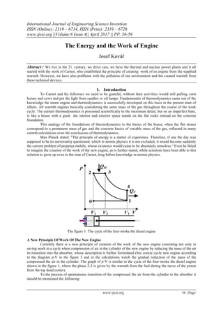
The figure 1: The cycle of the four-stroke the diesel engine
A New Principle Of Work Of The New Engine
Currently there is a new principle of creation of the work of the new engine consisting not only in
saving work in a cycle when compression of air in the cylinder of the new engine by reducing the mass of the air
its transition into the absorber, whose description is further formulated (See course cycle new engine according
to the diagram p-V in the figure 3 and in the calculations watch the gradual reduction of the mass of the
compressed the air in the cylinder. The graph of p-V is similar to the cycle of the four-stroke the diesel engine
shown in the figure 1, where the phase 2-3 is given by the warmth from the fuel during the move of the piston
from the top dead center).
To the process of spontaneous transition of the compressed the air from the cylinder to the absorber it
should be mentioned the following:
2. The energy and the work of engine
www.ijesi.org 57 | Page
The gas overflows always spontaneously from the space, where it is a higher pressure into the space, where
is the pressure lower. This is so even in the spontaneous the transition of the compressed air from the
cylinder to the absorber. Of course this effect is reflected positively in the small compression work.
The total internal energy at point 3 is then given by the sum of the inner energy of the air in the cylinder at
the top dead center of the piston and the inner the energy of the air in the absorber.
The expansion in the phase of the 3-4 is the internal energy of the air decreases and creates the work engine.
1. The state of volumes and phase 1-2: At start the temperature of air in the working cylinder (V1cylinder) and in the
absorber (Vabsorber ) is the same as it is in the surroundings. The piston in the working cylinder is moving in this
compression phase from the bottom dead center of the piston (BDC - the point 1) to the top dead center of the
piston (TDC; the point 2), the pressure and the temperature of air increase in the working cylinder and the part of
overpressure air spontaneously transmits by the open overpressure cover from the working cylinder to the
absorber. The work in this compression process with the spontaneous the transition of the compressed air from
the cylinder to the absorber is small, a result of decreasing the mass of the compressed air in the cylinder.
2. The state of volumes and phase 2-3: In TDC the working cylinder (V2cylinder) and the absorber (Vabsorber ) are the
same increased pressure and the temperature of the air. The working cylinder is connected with the absorber by
the open valve and creates the common volume (V3common = V2cylinder + Vabsorber ; the point 3).
3. The state of volumes and phase 3-4: The piston in the working cylinder is drifting from TDC to BDC and the
air is expanded. In BDC (V4common = V1cylinder + Vabsorber ; the point 4) the pressure and the temperature of the air
in the working cylinder and in the absorber decrease the same way. The work in this the expansion phase is
significantly greater than the work embedded in the compression phase.
In case of the thermodynamic cycle with polytropic expansion the temperature and pressure of air in
phase 1-2 increases, in phase 3-4 the temperature and pressure of air decreases. The cylinder with the absorber
after expansion at the BDC (V6common = V1cylinder + Vabsorber; the point 4) connects with the surroundings, will the
exhaust in the phase 4-5 to the TDC (V1cylinder ; the point 5) and subsequently sucking new air from the
surrounding area in the phase 5-6, thereby reaches the BDC of the piston the initial temperature and the air
pressure in the cylinder and absorber (V6common = V1cylinder + Vabsorber; the point 6). After that in the BDC of the
piston (the point 6) closes the connection between the cylinder and its surroundings and the interconnection
between the cylinder and the absorber. In the phase 6-1 the common volume of the cylinder with absorber is
separated to the volume of cylinder V1cylinder and to the volume of the absorber Vabsorber . After this open the cycle
repeats.
The absorber is a chamber on the cylinder head, whose the volume corresponds to the volume of the
cylinder at the top dead center of the piston.
The valve completely connects the cylinder with absorber when the expansion phase 3-4, when the
exhaust phase 4-5 and also in sucking the air from the surroundings of the phase 5-6.
The isothermal nor adiabatic expansion is not technically recoverable.
The thermodynamic processes in the phase 1-2 are very dynamic and thermodynamically complicated, but the
basic thermodynamic axiom p. V = n. R.T is valid.
The thermodynamic cycle with the polytropic expansion
and the graph p-V
V1cylinder = 500 cm3
; V2cylinder = 25 cm3
; Vabsorber = 25 cm3
; kexpansion = 1,25;
3. The energy and the work of engine
www.ijesi.org 58 | Page
p1 = 100 kPa; T1 = 293 K; p(in 0,525) = 101,31 kPa; T(in 0,525) = 296,84 K;
n1cylinder = 100 . 0,5 . 1/(8,314 . 293) = 0,02052543 mol; n1absorber = 0,00102627 mol;
ncommon = n1cylinder + n1absorber = 0,0215517 mol;
{p2 = p3 = 1914,92 kPa; T 2 = T 3 = 534,35 K}
The informative example of the calculation compression work (a increased pressure air in the
compression is divided in the ratio of the respective volume of the cylinder to a common volume of the cylinder
with the absorber, is given by the set pressure between the cylinder and the absorber; it is likewise the case with
the calculation of the work, since it takes in the account always default to the air mass in the cylinder at the
beginning of the respective compression changes):
A. pcal = (0,5/0,4)1,25
. 100 = 1,28684 . 100 = 128,684;
128,684 - 100 = 28,684 . 0,4/0,425 = 27; p(0,5-0,4) = 27 + 100 = 127 kPa;
T(0,5-0,4) = 127 . 0,425 . 8,314-1
. 0,0215517-1
= 301,232 K;
ncyl 127 = 127 . 0,4 / 8,314. 301,232 = 0,02028395 mol;
W0,5-0,4 = 0,02052543 . 0,4/0,425 . 127 = 2,453 J
p(in 0,425) = 131,94 kPa; T(in 0,425) = 312,95 K;
B. p(0,4-0,3) = 177,733 kPa ; T(0,4-0,3) = 322,373 K;
ncyl 177,33 = 177,733 . 0,3 / 8,314. 322,373 = 0,0198939 mol;;
W0,4-0,3 = 0,02028395 . 0,3/0,325 . 177,733 = 3,328 J
p(in 0,325) = 184,5 kPa; T(in 0,325) = 334,66 K;
C. p(0,3-0,2) = 282 kPa ; T(0,3-0,2) = 354,12 K;
ncyl 282 = 282 . 0,2 / 8,314. 354,12 = 0,01915664 mol;
W0,3-0,2 = 0,0198939 . 0,2/0,225 . 282 = 4,987 J
p(in 0,225) = 292,17 kPa; T(in 0,225) = 366,88 K;
D. p(0,2-0,15) = 386,6 kPa ; T(0,2-0,15) = 377,58 K;
ncyl 386,6 = 386,6 . 0,15 / 8,314. 377,58 = 0,01847288 mol;
W0,2-0,15 = 0,01915664 . 0,15/0,175. 386,6 = 6,348 J
p(in 0,175) = 400 kPa; T(in 0,175) = 390,66 K;
E. p(0,15-0,10) = 590,59 kPa ; T(0,15-0,1) = 412 K;
ncyl 590,59 = 590,59 . 0,10 / 8,314. 412 = 0,01724133 mol;
W0,15-0,1 = 0,01847288 . 0,1/0,125 . 590,59 = 8,728 J
p(in 0,125) = 609,15 kPa; T(in 0,125) = 504,36 K;
F. p(0,1-0,05) = 1133,62 kPa ; T(0,1-0,05) = 474,5 K;
ncyl 1133,62 = 1133,62 . 0,05 /8,314 . 474,5 = 0,01436783 mol;
W0,1-0,05 = 0,01724133 . 0,05/0,075 . 1133,62 = 13,03 J
p(in 0,075) = 1153,55 kPa; T(in 0,075) = 482,84 K
G. p(0,05-0,025) = 1914,92 kPa ; T(0,05-0,025) = 534,35 K;
ncyl 1914,92 = 1914,92 . 0,025 / 8,314. 534,35 = 0,01077585 mol;
W0,05-0,025 = 0,01436783 . 0,025/0,05 . 1914,92 = 13,757 J
p(in 0,05) = 1914,92 kPa; T(in 0,05) = 534,35 K
Wcompression 1-2 < 52,63 J ;
Wexpansion 3-4 = 1914,92 . 0,05 . 0,25-1
. ( 1 - (0,05/0,525)0,25
) = 170,23 J
The warmth transmits from the cylinder to the surroundings after the expanssion:
Q4-6 = (5/2) . 0,0215517 . 8,314 . (296,8 - 293) = 1,702 J
Wusefull = 170,23 - 52,63 - 1,7 > 116 J
The output of the four cylinders – four stroke-new engine with the turning f = 6000 min-1
:
P = 4 . 0,5f . Wusefull = 2 . 100 s-1
. 116 = 23 kW
x (V; 101
. dm3
) y (p; kPa) x (V; 101
. dm3
) y (p; kPa)
0,25 1914,92 0,5 1914,92
0,5 1133,6 0,75 1153,55
1 590,6 1,25 609,15
1,5 386,6 1,75 400
2 282 2,25 292,17
4. The energy and the work of engine
www.ijesi.org 59 | Page
3 177,7 3,25 184,5
4 127 4,25 131,94
5 100 5,25 101,31
The figure 3: The graph p-V of the new cycle
It may be possible considerate for the spontaneous transmission of the compressed air from the working
cylinder to the absorber the fine setting of the very small tightless of the valve instead the using of the
overpressure cover.
In the actual implementation of the new engine is used construction of the existing four-stroke engine
and the engine will be supplemented by the absorber with the valve (between the absorber and the working
cylinder) and the new engine including the absorber is thermally isolated from the surrounding area. The better
the new engine will be thermally isolated from the surroundings, the more it will approach to adiabatic
expansion and the higher will be his performance (at equal volumes and processes as when polytropic cycle will
be the performance of the new engine 31 kW).
The new engine will be compared to existing warmth engines easier, as it passes out of the cooling and
the fuel accessories and for the new engine work won't need a drop of fuel.
To achieve the same performance as the present engine will be required the larger the total volume of the new
engine.
II. Conclusion
The new principle can be applied in the piston engine and the rotary engine of the Wankel, which will
be using the spontaneous transition of the compressed the air from the cylinder to the absorber and the
subsequent expansion of the air from the common volume of the cylinder with absorber to create the work
engine. A very important benefit is that the new engines of the applying this cycle, they will not pollute our
environment and falls off the existing unnecessary waste of fuel resources, that can be more effectively use in
chemistry. Use of new engines for vehicles, especially for drive generators for production of electrical current
and other, the life on our world could be better than today.
About The Author
JOSEF KOVÁŔ is devoted to the creation work engine of 30 years. Fixed knowing the previous
knowledge of thermodynamics on the creation of work of the engine only of the warmth he used a warmth from
surroundings for work of the engine. How it follows from the previous, everything is completely different.
The author of the invention is looking for the manufacturer of the prototype new engine for the joint obtaining
of the international patent. After obtaining the international patent on the new engine, you can expect high
profits from licences for the next 20 years. Please, express your interest to the autor of this invention.
Contact: ingjkovar@seznam.cz