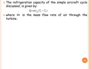
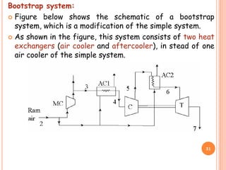
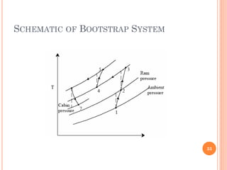
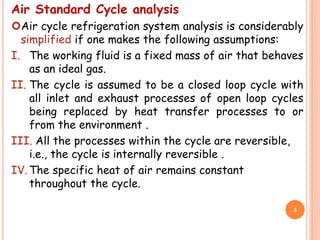
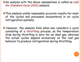
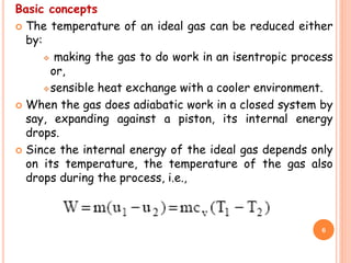
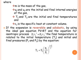
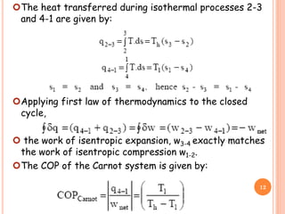
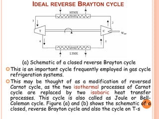
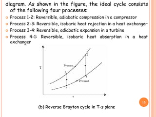
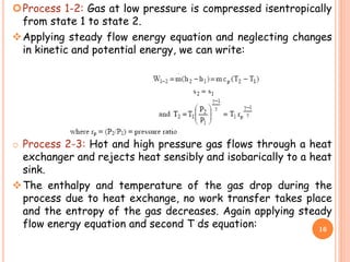
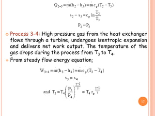
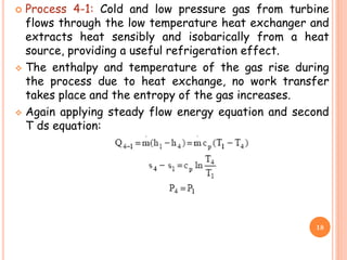
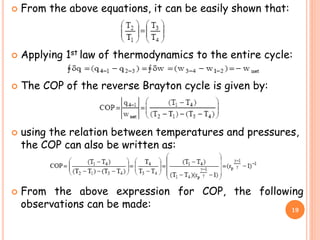
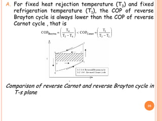
This document discusses air cycle refrigeration systems used in aircraft cabin cooling. It begins by introducing air cycle refrigeration and its advantages for aircraft applications. It then describes the ideal reverse Brayton cycle and compares it to the Carnot cycle. Key concepts of compression, expansion, and heat transfer processes are explained. Actual cycle analysis accounts for irreversibilities. Common aircraft refrigeration cycles are introduced, including the simple cycle and bootstrap system. The bootstrap system improves on the simple cycle by using a secondary compressor to boost efficiency during high-speed flight when ram air is available.
![B. COP of Brayton cycle approaches COP of Carnot cycle
as T1 approaches T4 (thin cycle), however, the specific
refrigeration effect [cp(T1-T4)] also reduces
simultaneously.
C. COP of reverse Brayton cycle decreases as the
pressure ratio rp increases
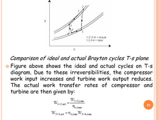
Actual reverse Brayton cycle:
The actual reverse Brayton cycle differs from the ideal
cycle due to:
I. Non-isentropic compression and expansion processes
II. Pressure drops in cold and hot heat exchangers
21](https://image.slidesharecdn.com/air-cyclerefrigeration-230305105401-e8d0d2df/85/Air-Cycle-refrigeration-pdf-21-320.jpg)