A simple N-channel MOSFET can be used as a diode, Switch and Active resistor. This presentation is a part of course of Analog CMOS Design, based on textbook of same title by Allen Holberg.
The attached narrated power point presentation explores the different methods of modulation of light such as direct modulation and external modulation. The material will immensely benefit KTU final year B Tech students who prepare for the subject EC 405, Optical Communications.
The attached narrated power point presentation attempts to explain the methods of computation of total power loss and system rise time in a fiber optic link. The material will be useful for KTU final year B Tech students who prepare for the subject EC 405, Optical Communications.
EEE 117L Network Analysis Laboratory Lab 1
1
EEE 117L Network Analysis Laboratory
Lab 1 – Voltage/Current Division and Filters
Lab Overview
The objective of Lab 1 is to familiarize students with a variety of basic applications of
passive R, C devices, and also how to measure the performance of these circuits using
both Spice simulations and the Digilent Analog Discovery 2 on the circuits constructed.
Prelab
Before coming to lab, students need to complete the following items for each of the
circuits studied in this lab :
• Any hand calculations needed to determine the values of components used in the
circuits such as resistors and capacitors, or specifications such as pole frequencies.
• A Spice simulation of each circuit to get familiar with how it works, and determine
what to expect when the circuit is built and its performance is measured.
Making connections on a Breadboard
Breadboards are used to easily construct circuits without the need to solder parts on a
printed circuit board. As seen in Figure 0 they have columns of pins that are connected
together internally, so that all the wires inserted in a column are shorted together. Note
that the columns on top and bottom are not connected together. There are also rows of
pins at the top and bottom that are connected together. These rows are intended for use
as the power supplies, and are typically labeled + and – and color coded red and blue for
the positive and negative power supplies. These rows are not connected in the middle.
Figure 0.
EEE 117L Network Analysis Laboratory Lab 1
2
Circuits to be studied
When choosing resistor and capacitor values use standard values available to you,
and keep all resistor values between 100 W and 100 kW.
1. Voltage and Current Dividers
One of the most commonly used circuits is a voltage divider
like the one shown in Figure 1.a. For example, if a signal is
too large to be input to a voltmeter or oscilloscope it can be
attenuated (reduced in size) using voltage division. The DC
voltage that an AC signal like a sine wave varies around can
also be reduced using this circuit.
For example, if all of the resistors in this circuit are the same
value, and the VS input source provides a DC voltage of 4V,
then the voltages in this circuit will be VA = 4V, VB = 3V,
VC = 2V, and VD = 1V. That is, voltage division will cause the voltage at node B to be
¾ of VS , the voltage at node C to be ½ of VS , and the voltage at node D to be ¼ of VS.
If a sine wave with an amplitude of 1V is then added so that VS = 4 + sin(wt) Volts, then
voltage division will cause the new values of VA , VB , VC and VD to be :
VA = 1.00*VS = 1.00*(4 + sin(wt)) = 4 + 1.00*sin(wt) Volts
VB = 0.75*VS = 0.75*(4 + sin(wt)) = 3 + 0.75*sin(wt) Volts
VC = 0.50*VS = 0.50*(4 + sin(wt)) = 2 + 0.50*sin(wt) Volts
VD = 0.25*VS = 0.25*(4 + sin(wt)) = 1 + 0.25*sin(wt) Volts
In this example both the amplitude of the ...
Electronics and Communication Engineering is the Branch of Engineering. Electronics and Communication Engineering field requires an understanding of core areas including Engineering Graphics, Computer Programming,Electronics Devices and Circuits-I, Network Analysis, Signals and Systems, Communication Systems, Electromagnetics Engineering, Digital Signal Processing, Embedded Systems, Microprocessor and Computer Architecture. Ekeeda offers Online Mechanical Engineering Courses for all the Subjects as per the Syllabus. Visit : https://ekeeda.com/streamdetails/stream/Electronics-and-Communication-Engineering
Electrical current, voltage, resistance, capacitance, and inductance are a few of the basic elements of electronics and radio. Apart from current, voltage, resistance, capacitance, and inductance, there are many other interesting elements to electronic technology. ... Use Electronics Notes to learn electronics online.
KuberTENes Birthday Bash Guadalajara - K8sGPT first impressionsVictor Morales
K8sGPT is a tool that analyzes and diagnoses Kubernetes clusters. This presentation was used to share the requirements and dependencies to deploy K8sGPT in a local environment.
Water billing management system project report.pdfKamal Acharya
Our project entitled “Water Billing Management System” aims is to generate Water bill with all the charges and penalty. Manual system that is employed is extremely laborious and quite inadequate. It only makes the process more difficult and hard.
The aim of our project is to develop a system that is meant to partially computerize the work performed in the Water Board like generating monthly Water bill, record of consuming unit of water, store record of the customer and previous unpaid record.
We used HTML/PHP as front end and MYSQL as back end for developing our project. HTML is primarily a visual design environment. We can create a android application by designing the form and that make up the user interface. Adding android application code to the form and the objects such as buttons and text boxes on them and adding any required support code in additional modular.
MySQL is free open source database that facilitates the effective management of the databases by connecting them to the software. It is a stable ,reliable and the powerful solution with the advanced features and advantages which are as follows: Data Security.MySQL is free open source database that facilitates the effective management of the databases by connecting them to the software.
Harnessing WebAssembly for Real-time Stateless Streaming PipelinesChristina Lin
Traditionally, dealing with real-time data pipelines has involved significant overhead, even for straightforward tasks like data transformation or masking. However, in this talk, we’ll venture into the dynamic realm of WebAssembly (WASM) and discover how it can revolutionize the creation of stateless streaming pipelines within a Kafka (Redpanda) broker. These pipelines are adept at managing low-latency, high-data-volume scenarios.
We have compiled the most important slides from each speaker's presentation. This year’s compilation, available for free, captures the key insights and contributions shared during the DfMAy 2024 conference.
NUMERICAL SIMULATIONS OF HEAT AND MASS TRANSFER IN CONDENSING HEAT EXCHANGERS...ssuser7dcef0
Power plants release a large amount of water vapor into the
atmosphere through the stack. The flue gas can be a potential
source for obtaining much needed cooling water for a power
plant. If a power plant could recover and reuse a portion of this
moisture, it could reduce its total cooling water intake
requirement. One of the most practical way to recover water
from flue gas is to use a condensing heat exchanger. The power
plant could also recover latent heat due to condensation as well
as sensible heat due to lowering the flue gas exit temperature.
Additionally, harmful acids released from the stack can be
reduced in a condensing heat exchanger by acid condensation. reduced in a condensing heat exchanger by acid condensation.
Condensation of vapors in flue gas is a complicated
phenomenon since heat and mass transfer of water vapor and
various acids simultaneously occur in the presence of noncondensable
gases such as nitrogen and oxygen. Design of a
condenser depends on the knowledge and understanding of the
heat and mass transfer processes. A computer program for
numerical simulations of water (H2O) and sulfuric acid (H2SO4)
condensation in a flue gas condensing heat exchanger was
developed using MATLAB. Governing equations based on
mass and energy balances for the system were derived to
predict variables such as flue gas exit temperature, cooling
water outlet temperature, mole fraction and condensation rates
of water and sulfuric acid vapors. The equations were solved
using an iterative solution technique with calculations of heat
and mass transfer coefficients and physical properties.
Online aptitude test management system project report.pdfKamal Acharya
The purpose of on-line aptitude test system is to take online test in an efficient manner and no time wasting for checking the paper. The main objective of on-line aptitude test system is to efficiently evaluate the candidate thoroughly through a fully automated system that not only saves lot of time but also gives fast results. For students they give papers according to their convenience and time and there is no need of using extra thing like paper, pen etc. This can be used in educational institutions as well as in corporate world. Can be used anywhere any time as it is a web based application (user Location doesn’t matter). No restriction that examiner has to be present when the candidate takes the test.
Every time when lecturers/professors need to conduct examinations they have to sit down think about the questions and then create a whole new set of questions for each and every exam. In some cases the professor may want to give an open book online exam that is the student can take the exam any time anywhere, but the student might have to answer the questions in a limited time period. The professor may want to change the sequence of questions for every student. The problem that a student has is whenever a date for the exam is declared the student has to take it and there is no way he can take it at some other time. This project will create an interface for the examiner to create and store questions in a repository. It will also create an interface for the student to take examinations at his convenience and the questions and/or exams may be timed. Thereby creating an application which can be used by examiners and examinee’s simultaneously.
Examination System is very useful for Teachers/Professors. As in the teaching profession, you are responsible for writing question papers. In the conventional method, you write the question paper on paper, keep question papers separate from answers and all this information you have to keep in a locker to avoid unauthorized access. Using the Examination System you can create a question paper and everything will be written to a single exam file in encrypted format. You can set the General and Administrator password to avoid unauthorized access to your question paper. Every time you start the examination, the program shuffles all the questions and selects them randomly from the database, which reduces the chances of memorizing the questions.
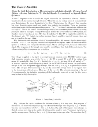
1. The Class-D Amplifier
(From the book Introduction to Electroacoustics and Audio Amplifier Design, Second
Edition - Revised Printing, by W. Marshall Leach, Jr., published by Kendall/Hunt,
c° 2001.)
A class-D amplifier is one in which the output transistors are operated as switches. When a
transistor is off, the current through it is zero. When it is on, the voltage across it is small, ideally
zero. In each case, the power dissipation is very low. This increases the efficiency, thus requiring
less power from the power supply and smaller heat sinks for the amplifier. These are important
advantages in portable battery-powered equipment. The “D” in class-D is sometimes said to stand
for “digital.” This is not correct because the operation of the class-D amplifier is based on analog
principles. There is no digital coding of the signal. Before the advent of the class-D amplifier, the
standard classes were class-A, class-AB, class-B, and class-C. The “D” is simply the next letter in
the alphabet after “C.” Indeed, the earliest work on class-D amplifiers involved vacuum tubes and
can be traced to the early 1950s.
Fig. 1 shows the basic simplified circuit of a class-D amplifier. We assume a bipolar power supply
so that V − = −V +. The amplifier consists of a comparator driving two MOSFET transistors which
operate as switches. The comparator has two inputs. One is a triangle wave, the other is the audio
signal. The frequency of the triangle wave must be much higher than that of the audio input. The
voltage output of the comparator can be written
vC = −V1 for vS > vT vC = +V1 for vS < vT (1)
This voltage is applied to the input of a complementary common-source MOSFET output stage.
Each transistor operates as a switch. For vC = −V1, M1 is on and M2 is off. If the voltage drop
across M1 is negligible, then v0
O = V +
. Similarly, for vC = +V1, M2 is on, M1 is off, and v0
O = V −
.
In practice, there is a small voltage drop across the on MOSFET switch so that the peak output
voltage is less than the power supply voltage. For the case vS = 0, v0
O is a symmetrical square
wave. The low-pass filter consisting of L1 and C1 passes the average value of the square wave
to the loudspeaker, which is zero. Thus vO = 0 for vS = 0. The network consisting of R1 and
C2 compensates for the inductive impedance of the loudspeaker voice coil so that the filter sees a
resistive load at high frequencies.
Figure 1: Basic class-D amplifier.
Fig. 2 shows the circuit waveforms for the case where vS is a sine wave. For purposes of
illustration, the sine wave frequency is fS = 1 kHz and the triangle wave frequency is fT = 20 kHz.
The sine wave amplitude is 0.75VT P . For vS > 0, the duty cycle of the square wave changes so
that v0
O spends more time at its positive level than at its negative level. This causes v0
O to have a
positive average value. Similarly, for vS < 0, v0
O has a negative average value. The waveform for v0
O
1
2. is said to be pulse-width-modulated. The passive filter consisting of L1 and C1 passes the average
or low-frequency value of v0
O to the loudspeaker load and rejects the higher-frequency harmonics of
the switching waveform.
Figure 2: Amplifier voltage waveforms.
The effective gain of the amplifier can be determined by applying a dc voltage at the input and
calculating the ratio of hv0
Oi to vS, where hv0
Oi denotes the low-frequency time average of v0
O. If vS
is increased, hv0
Oi increases linearly until it reaches the level VOP , which corresponds to the positive
clipping voltage at the output. This occurs when vS = VT P . It follows that the effective gain k is
given by
k =
hv0
Oi
vS
=
VOP
VTP
(2)
Fig. 3 shows the waveforms of the output voltage vO for two values of the cutoff frequency of
the LC filter. The transfer function of the filter is
Vo
V 0
o
=
1
(s/ωc)2
+ (1/Qc) (s/ωc) + 1
(3)
where ωc = 2πfc = 1/
√
L1C1 is the resonance frequency and Qc = 1/ (ωcRLC1) is the quality
factor. The load resistance RL is the effective high-frequency resistance of the loudspeaker voice
coil in parallel with the matching network consisting of R1 and C2. The quality factor is Qc = 1/
√
2
for the waveforms in Fig. 3 so that the gain is down by 3 dB at ωc. The signal frequency is fS = 1
kHz. The filter resonance frequency for the vO1 waveform is fc = 1 kHz. For the vO2 waveform, it
is fc = 8 kHz. The harmonics of the pulse-width-modulated signal are clearly visible on the vO2
waveform.
For minimum distortion, the frequency of the triangle wave should be as high as possible
compared to the cutoff frequency of the filter. Because the filter resonance frequency corresponds
to the signal frequency for the vO1 waveform in Fig. 3, the phase lag is 90o. The phase lag for the
vO2 waveform is less because the resonance frequency is greater than the signal frequency. A higher-
order filter can be used to more effectively remove the high-frequency switching harmonics. For
example, a third-order LC filter or a fourth-order filter consisting of the cascade of two second-order
LC filters could be used.
Fig. 4 shows the spectrum of the v0
O waveform. It contains a fundamental at fS. Above fS,
the significant switching harmonics are at fT , fT ± 2fS, 2fT ± fS, 2fT ± 3fS, etc. The lowest of
these is at the frequency fT − 2fS. The triangle wave frequency must be chosen high enough so
2
3. Figure 3: Output voltage waveforms for two different LC filter cutoff frequencies.
that the lowest significant harmonic is well above the highest signal frequency of interest. Thus we
have the requirement fT − 2fS À fS or fT À 3fS. To minimize ripple on the output, the cutoff
frequency of the LC filter should be much lower than fT . For example, in a wideband amplifier
with a maximum signal frequency of 20 kHz, the switching frequency should ideally be 600 kHz
or greater. Because of limitations imposed by a high switching frequency, a more practical value
might be 300 kHz. The −3 dB frequency of the LC filter should be much lower than the switching
frequency. For example, it might be 30 kHz for a 300 kHz switching frequency. Note that the
amplitude of the harmonic at fT is larger than that of the signal. At the signal clipping level, the
signal harmonic becomes 1.5 times as large as the harmonic at fT .
Figure 4: Unfiltered spectrum of the output voltage.
Negative feedback can be used around the basic amplifier circuit to improve its performance.
Fig. 5 shows such a circuit. The input op amp acts as an integrator to set the bandwidth. For
a sinusoidal input signal with a frequency much lower than the switching frequency, the effective
transfer function for the circuit and its pole frequency are given by
V 0
o
Vs
= −
RF
R2
1
1 + s/ω0
ω0 = 2πf0 =
k
RF CF
(4)
The pole frequency must be greater than the highest frequency to amplified but lower than the
switching frequency. Because the integrator has a very high gain at dc, it acts to minimize dc
offsets at the output. For a wide band amplifier, a typical value of f0 might be 60 kHz.
Class-D amplifiers are often operated in a bridged configuration to increase the output power
without increasing the power supply voltages. A bridged output stage is shown in Fig. 6. A typical
input circuit is shown in Fig. 7. The feedback voltage vF is proportional to the difference voltage
3
4. Figure 5: Amplifier with negative feedback.
v0
O1 −v0
O2. The bridge circuit is often designed with V − = 0 and a dc offset at each output of V +/2
V, thus eliminating the need for a bipolar power supply.
Figure 6: Bridged output stage.
Figure 7: Input stage to the bridged amplifier with feedback.
In the circuit of Fig. 7, a diff amp is used to subtract v0
O2 from v0
O1. The capacitors labeled C3
act as low-pass filters to limit the rise time of the signals applied to the op amp to prevent slewing.
The transfer function for the diff amp and its pole frequency are given by
Vf
V 0
o1 − V 0
o2
=
R5
R3 + R4
1
1 + s/ω1
ω1 = 2πf1 =
1
(R3kR4) C3
(5)
4
5. The overall transfer function for the amplifier is given by
V 0
o1 − V 0
o2
Vs
= −
RF
R2
R3 + R4
R5
1 + s/ω1
s2/ω1ω2 + s/ω2 + 1
= −
RF
R2
R3 + R4
R5
1 + s/ω1
(s/ω0)2
+ (1/Q0) (s/ω0) + 1
(6)
where ω2, ω0, and Q0 are given by
ω2 = 2πf2 =
R5
R3 + R4
k
RF CF
ω0 = 2πf0 =
√
ω1ω2 Q0 =
r
ω2
ω1
(7)
The amplifier should exhibit good stability for Q0 ≤ 1. Thus we have the condition ω1 ≥ ω2.
However, the simple model used here neglects higher order poles. Because the existence of such
poles degrades stability, a conservative approach might be to design for Q0 ≤ 0.5 so that the poles
in Eq. (6) are real. This requires ω1 ≥ 4ω2. For example, in a wideband amplifier utilizing a
switching frequency of 300 kHz, f1 might be chosen to be equal to the switching frequency and f2
might be chosen to be 75 kHz.
An example triangle wave generator circuit is shown in Fig. 8. The circuit consists of an inte-
grator driving a comparator that is connected as a Schmitt trigger. The output of the comparator
drives the input to the integrator. Let the comparator output voltages be +V1 and −V1. When the
voltage is at the −V1 level, the triangle wave output rises with the slope m = V1/R6C4. Let the
peak values of the triangle wave be +VTP and −VTP . It follows that 2VTP = mT/2 = V1/2fT R6C4,
where T = 1/fT is the period of the triangle wave. The comparator switches states when the volt-
age at its non-inverting input goes through zero. This occurs when V1/R8 = VTP /R7. Solution for
fT and VTP yields
fT =
R8
4R6R7C4
VTP =
R7
R8
V1 (8)
Figure 8: Triangle wave generator.
A problem called “shoot through” can reduce the efficiency of class-D amplifiers and lead to
potential failure of the output devices. This occurs during the transition when one device is being
cut off and another is being cut on. During the transition, both devices are on and a large current
pulse can flow through the two. This can be eliminated by driving the gates of the MOSFETs with
asymmetrical square waves such that one device is cut off before the other is cut on. One way of
achieving this in the circuit of Figs. 1 and 5 is to use two comparators, one for each MOSFET.
A positive dc offset is added to the triangle wave input to the comparator which drives M1 and a
negative dc offset is added to the triangle wave input to the comparator which drives M2. This
effectively adds crossover distortion to the v0
O output waveform, but the frequency components are
above the switching frequency, thus outside the audio band.
5
6. The high switching frequency used in class-D amplifiers is a potential source of rf interference
with other electronic equipment. The amplifiers must be properly shielded and grounded to prevent
radiation of the switching harmonics. In addition, low-pass filters must be used on all input and
output leads, including the power supply leads.
A variation of the class-D amplifier is called a filterless class-D amplifier. In the absence of an
input signal, its output signal is zero rather than a symmetrical square wave. This eliminates the
need of a low-pass filter to prevent application of the square wave to the loudspeaker. When the
input voltage goes positive, the output voltage is a train of pulse width modulated pulses which
switch between 0 and +VOP . When the input voltage goes negative, the output voltage is a train of
pulse width modulated pulses which switch between 0 and −VOP . This is illustrated in Fig. 9. The
loudspeaker responds to the average value of the signal, which is the audio signal. Because there is
no filter, rf interference problems require the amplifier to be mounted as close to the loudspeaker
as possible. The spectrum of the output signal is shown in Fig. 10. One problem with the filterless
class-D amplifier is crossover distortion. To eliminate this, the FET control logic must be designed
so that the amplifier puts out very narrow alternating positive and negative pulses in the absence
of an input signal. In effect, this biases the amplifier in the class-AB mode.
Figure 9: Amplifier voltage waveforms.
Figure 10: Spectrum of the output voltage v0
O.
6