Download to read offline

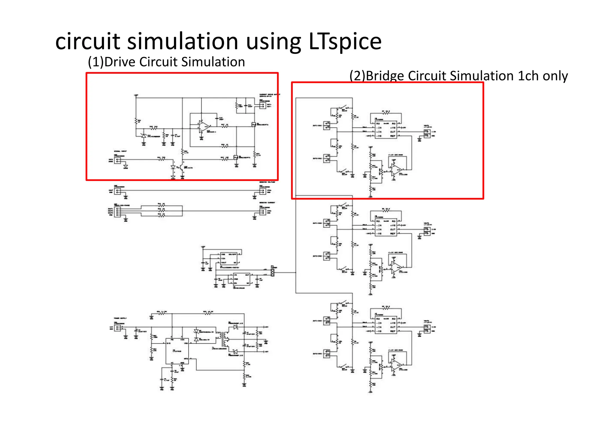
![(1)Drive Circuit Simulation
Insert 250[Ω]between Out+ and out-](https://image.slidesharecdn.com/ltspice-240229131324-a67132dc/85/Circuit-simulation-using-LTspice-Case-study-2-320.jpg)
![(2)Bridge Circuit Simulation 1ch only
DUT1=DUT2=100[Ω] Setting to 1[V] or 5[V]](https://image.slidesharecdn.com/ltspice-240229131324-a67132dc/85/Circuit-simulation-using-LTspice-Case-study-3-320.jpg)

This document discusses circuit simulations using LTspice. It describes driving a circuit simulation by inserting a 250 ohm resistor between the output terminals. It also describes simulating a 1 channel bridge circuit where the DUT1 and DUT2 resistors are both set to 100 ohms and the input voltage is set to either 1V or 5V.


