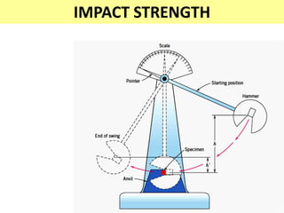
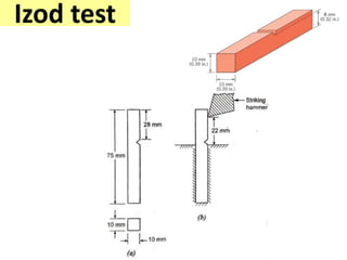
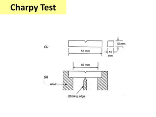
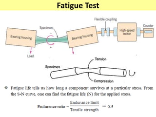
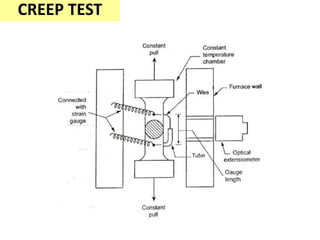
.
TESTING OF
MECHANICAL
PROPERTIES
UNIT -5
Plastic deformation
• It’s a deformation of a body which remains
even after removing the external load from
the body.
• In crystalline material deformation occur at a
temperature lower than 0.4Tm
Tm – melting point temp. of a material
• The plastic deformation may occur under the
tensile, compressive or torsional stresses.
.
• The property of Palstic deformation makes
the metal suitable for various forming
processes such as rolling , forging, pressing,
drawing, spinning, extrusion and stamping
Mechanism of plastic
deformation
.
MECHANISM OF PLASTIC DEFORMATION
• Plastic deformation is defined as a process in
which the object due to applied force changes its
size or shape in a way that is not reversible.
• Plastic deformation is seen in many objects,
including:
Slip
• Sliding of blocks of the crystal over one another along
definite crystallographic planes called slip planes
• i.e --- displacement of one part of
the crystal relative to another along
a particular plane and direction
The combination of slip plane and
slip direction is called slip system
Mechanism of slip
• When Shear stress applied exceeds the critical
value slip occur.
TWINNING
• The second important mechanism in the
metal deformation.
• Here the atoms in the part of a crystal
subjected to stress, rearrange themselves so
that one part of the crystal become the
mirror to the other.
.
Fracture
.
Fracture - definition
• Fracture is the mechanical failure of the material
which will produce the separation or
fragmentation of a solid into 2 or more parts
under the action of stress.
Brittle fracture
Ductile fracture
Fatigue fracture
Creep fracture
Brittle fracture
• Its a fracture which takes place by the rapid
propagation of crack with a negligible
deformation.
• Mostly amorphous material like glasses
having this kind of fractures.
Mechanism of
brittle
mechanism
.
• Now the tensile stress is applied at the both
sides of the material.
• So the stress is maximum at the tip of the crack
.
Griffith’s theory is applicable only for brittle fracture
.
The fracture which takes place by a slow propagation
of crack with appreciable plastic deformation.
DUCTILE FRACTURE
.
.
.
FATIGUE FRACTURE
• Failure occur due to repeated or
fluctuating load
Stress
Cycles
.
.
.
.
CREEP
• It’s a slow and permanent deformation in metal under
steady load at constant temperature.
.
Factors affecting creep
• Grain size
• Thermal stability of the micro- structure
• Chemical reactions
• Prior strain (cold working or work hardening)
Mechanism of creep fracture
(a) Dislocation climb
(b) Vacancy diffusion
( c ) grain boundary sliding
.
Mechanical tests of metals
Destructive tests
Classification of mechanical tests
• Destructive test
• Non – Destructive test
Tensile test
destructive test – ductile material
We find
.
.
.
.
.
CALCULATION
.
.
.
COMPRESSION TEST
Pure Shear force
• A pure shear force applied top and bottom parallel to its
faces
.
Shear stress,
Where, F = Shear force applied
A = Area of shear
Shear strain: The shear strain is defined as the
tangent of the strain angle θ.
Shear strain, γ = tan θ
Limitations of shear test
• Need attachment with UTM machine .
• Material at last gets bend
• So we will get the bending stress also, not the
pure shear type.
• Very difficult in processing
Torsion test
• Rotational force given to material about longitudinal axis.
• This torsional forces produce a rotational motion about
the longitudinal axis of one end of the member relative
to the other end.
.
HARDNESS TEST
Brinell Hardness
Vickers Hardness
Rockwell Hardness
Types of Hardness Test
Brinell hardness test
Standard loads range between 500 kg and 3000 kg in 500 kg increments.
During a test, the load is maintained constant for 10 to 15 seconds.
.
Vickers hardness test
High accuracy than brinell due to square based
diamond pyramid indenter
The Vickers hardness test method consists of
indenting the test material with a diamond
indenter, in the form of a right pyramid with a
square base and an angle of 136 degrees between
opposite faces subjected to a load of 1 to 100 kgf.
The full load is normally applied for 10 to 15
seconds.
.
.
Where
P = Applied load in kg,
θ = Angle between the opposite faces of diamond = 136°,
D = Mean diagonal length in mm.
Advantages
• The diagonals of the square indentation can be measured
more accurately than the diameters of the circles.
• This method is suitable for hard materials as well as for soft
materials.
• The Vickers indenter is capable of giving geometrically
similar impression with different loads. Thus, the hardness
number is independent of the load applied.
.
Rockwell hardness test
Industries used due to its high accuracy,
simplicity and rapidity
In this test , the dial gives the direct reading of
hardness; no need of measuring indentation
diameter or diagonal length using the microscope
.
Advantages
• Simple
• Reading taken directly
• Time consuming process
• Suitable for mass production
• We can measure any range of value with various
indenters.
• Metallic and also plastics used
limitations
Its not accurate than vickers test
IMPACT TEST-
TO STUDY THE BEHAVIOUR OF THE MATERIAL UNDER SUDDEN LOAD
IZOD TEST
CHARPY TEST
IMPACT STRENGTH
Izod test
Charpy Test
Fatigue Test
CREEP TEST

TESTING OF MECHANICAL PROPERTIES

  • 1.
  • 2.
    Plastic deformation • It’sa deformation of a body which remains even after removing the external load from the body. • In crystalline material deformation occur at a temperature lower than 0.4Tm Tm – melting point temp. of a material • The plastic deformation may occur under the tensile, compressive or torsional stresses.
  • 3.
    . • The propertyof Palstic deformation makes the metal suitable for various forming processes such as rolling , forging, pressing, drawing, spinning, extrusion and stamping
  • 4.
  • 5.
    MECHANISM OF PLASTICDEFORMATION • Plastic deformation is defined as a process in which the object due to applied force changes its size or shape in a way that is not reversible. • Plastic deformation is seen in many objects, including:
  • 6.
    Slip • Sliding ofblocks of the crystal over one another along definite crystallographic planes called slip planes • i.e --- displacement of one part of the crystal relative to another along a particular plane and direction The combination of slip plane and slip direction is called slip system
  • 7.
    Mechanism of slip •When Shear stress applied exceeds the critical value slip occur.
  • 8.
    TWINNING • The secondimportant mechanism in the metal deformation. • Here the atoms in the part of a crystal subjected to stress, rearrange themselves so that one part of the crystal become the mirror to the other.
  • 9.
  • 10.
  • 11.
    Fracture - definition •Fracture is the mechanical failure of the material which will produce the separation or fragmentation of a solid into 2 or more parts under the action of stress. Brittle fracture Ductile fracture Fatigue fracture Creep fracture
  • 12.
    Brittle fracture • Itsa fracture which takes place by the rapid propagation of crack with a negligible deformation. • Mostly amorphous material like glasses having this kind of fractures.
  • 13.
  • 14.
    . • Now thetensile stress is applied at the both sides of the material. • So the stress is maximum at the tip of the crack
  • 16.
    . Griffith’s theory isapplicable only for brittle fracture
  • 17.
    . The fracture whichtakes place by a slow propagation of crack with appreciable plastic deformation. DUCTILE FRACTURE
  • 18.
  • 19.
  • 20.
  • 21.
    FATIGUE FRACTURE • Failureoccur due to repeated or fluctuating load
  • 22.
  • 23.
  • 24.
  • 25.
  • 26.
  • 27.
    CREEP • It’s aslow and permanent deformation in metal under steady load at constant temperature.
  • 28.
  • 29.
    Factors affecting creep •Grain size • Thermal stability of the micro- structure • Chemical reactions • Prior strain (cold working or work hardening)
  • 30.
    Mechanism of creepfracture (a) Dislocation climb (b) Vacancy diffusion
  • 31.
    ( c )grain boundary sliding
  • 32.
  • 33.
    Mechanical tests ofmetals Destructive tests
  • 34.
    Classification of mechanicaltests • Destructive test • Non – Destructive test
  • 35.
    Tensile test destructive test– ductile material
  • 36.
  • 37.
  • 38.
  • 39.
  • 40.
  • 41.
  • 42.
  • 43.
  • 44.
  • 45.
  • 46.
  • 47.
    Pure Shear force •A pure shear force applied top and bottom parallel to its faces
  • 48.
    . Shear stress, Where, F= Shear force applied A = Area of shear Shear strain: The shear strain is defined as the tangent of the strain angle θ. Shear strain, γ = tan θ
  • 49.
    Limitations of sheartest • Need attachment with UTM machine . • Material at last gets bend • So we will get the bending stress also, not the pure shear type. • Very difficult in processing
  • 50.
    Torsion test • Rotationalforce given to material about longitudinal axis. • This torsional forces produce a rotational motion about the longitudinal axis of one end of the member relative to the other end.
  • 51.
  • 52.
    HARDNESS TEST Brinell Hardness VickersHardness Rockwell Hardness Types of Hardness Test
  • 53.
    Brinell hardness test Standardloads range between 500 kg and 3000 kg in 500 kg increments. During a test, the load is maintained constant for 10 to 15 seconds.
  • 55.
  • 56.
    Vickers hardness test Highaccuracy than brinell due to square based diamond pyramid indenter The Vickers hardness test method consists of indenting the test material with a diamond indenter, in the form of a right pyramid with a square base and an angle of 136 degrees between opposite faces subjected to a load of 1 to 100 kgf. The full load is normally applied for 10 to 15 seconds.
  • 57.
  • 58.
    . Where P = Appliedload in kg, θ = Angle between the opposite faces of diamond = 136°, D = Mean diagonal length in mm.
  • 59.
    Advantages • The diagonalsof the square indentation can be measured more accurately than the diameters of the circles. • This method is suitable for hard materials as well as for soft materials. • The Vickers indenter is capable of giving geometrically similar impression with different loads. Thus, the hardness number is independent of the load applied.
  • 60.
  • 61.
    Rockwell hardness test Industriesused due to its high accuracy, simplicity and rapidity In this test , the dial gives the direct reading of hardness; no need of measuring indentation diameter or diagonal length using the microscope
  • 62.
  • 63.
    Advantages • Simple • Readingtaken directly • Time consuming process • Suitable for mass production • We can measure any range of value with various indenters. • Metallic and also plastics used limitations Its not accurate than vickers test
  • 64.
    IMPACT TEST- TO STUDYTHE BEHAVIOUR OF THE MATERIAL UNDER SUDDEN LOAD IZOD TEST CHARPY TEST
  • 65.
  • 66.
  • 67.
  • 68.
  • 69.