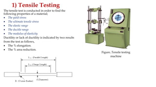
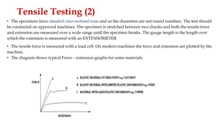
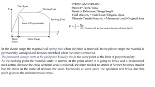
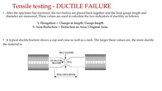
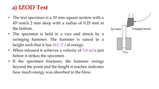
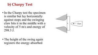
MATERIAL TESTING
By
Dr. Kimutai
INTRODUCTION TO DESTRUCTIVE TESTS
• In order to determine the properties of materials many standard tests have been
devised.
Destructive vs. Non - destructive Tests
• Testing can be divided up into destructive and non-destructive and as the names
imply, one destroys the sample and the other does not.
• Non - destructive tests may be carried out on the actual component or structure to
see if it has any defects (e.g. checking aircraft skins for cracks).
• Destructive tests may use a specimen from a batch of new material to check it
meets the specification. Specimens may be made from a structure that has been in
use (e.g. checking material that failed unexpectedly).
1) Tensile Testing
The tensile test is conducted in order to find the
following properties of a material;
 The yield stress
 The ultimate tensile stress
 The elastic range
 The ductile range
 The modulus of elasticity
Ductility or lack of ductility is indicated by two results
from the test as follows,
 The % elongation.
 The % area reduction.
Figure..Tensile testing
machine
Tensile Testing (2)
• The specimens have standard cross-sectional areas and so the diameters are not round numbers. The test should
be conducted on approved machines. The specimen is stretched between two chucks and both the tensile force
and extension are measured over a wide range until the specimen breaks. The gauge length is the length over
which the extension is measured with an EXTENSOMETER
• The tensile force is measured with a load cell. On modern machines the force and extension are plotted by the
machine.
• The diagram shows typical Force – extension graphs for some materials.
In the elastic range the material will spring back when the force is removed. In the plastic range the material is
permanently damaged and remains stretched when the force is removed.
The permanent damage starts at the yield point. Usually this is the same point as the limit of proportionality.
At the necking point the material starts to narrow at the point where it is going to break and a pronounced
neck forms. Because the cross sectional area is reduced, the force needed to stretch it further becomes smaller
but the stress in the material remains the same. Eventually at some point the specimen will break and this
point gives us the ultimate tensile stress.
Tensile testing - DUCTILE FAILURE
• After the specimen has fractured, the two halves are placed back together and the final gauge length and
diameter are measured. These values are used to calculate the two indicators of ductility as follows.
• A typical ductile fracture shows a cup and cone as well as a neck. The larger these values are, the more ductile
the material is
QUIZ
A tensile test uses a test specimen that has a gage length of 50 mm and an area =
200 mm2 . During the test the specimen yields under a load of 98,000 N. The
corresponding gage length = 50.23 mm. This is the 0.2 percent yield point. The
maximum load = 168,000 N is reached at a gage length = 64.2 mm. Determine:
(a) yield strength Y, (b) modulus of elasticity E, and (c) tensile strength TS
2) Impact Tests
• These tests are conducted to determine the TOUGHNESS or BRITTLENESS of the material. There
are several forms of the tests. The basic principle in all cases is that the specimen is struck with a
hammer and the energy absorbed is measured. The greater the energy absorbed, the tougher the
material, the smaller the energy absorbed, the more brittle the material.
• Brittleness is indicated by the easy way that a crack spreads through the material. Cracks always
start at some scratch or blemish on the surface. In tension these open out.
• A tough material is difficult to pull apart but a brittle material spreads the crack easily.
• In these tests, the specimen has a notch cut in it to make the crack start at that point. The stress level
in a material is greatly increased at a notch or any sharp corner and this point is important in the
design of components. Where sharp corners occur a radius should be used to reduce the effect.
Transition Temperature ; Some materials become brittle when cold and so notch bar tests are
conducted to find the temperature at which they become brittle.
• Some steels of certain compositions have been known to crack at cold temperatures and cause
disasters. Notched bar tests are conducted over a range of temperatures to determine where a material
becomes brittle and this is one of the properties that should be seriously considered in material selection.
a) IZOD Test
• The test specimen is a 10 mm square section with a
45o notch 2 mm deep with a radius of 0.25 mm at
the bottom.
• The specimen is held in a vice and struck by a
swinging hammer. The hammer is raised to a
height such that it has 162.72 J of energy.
• When released it achieves a velocity of 3.8 m/s just
before it strikes the specimen.
• If the specimen fractures, the hammer swings
beyond the point and the height it reaches indicates
how much energy was absorbed in the blow.
b) Charpy Test
• In the Charpy test the specimen
is similar but lay horizontally
against stops and the swinging
claw hits it in the middle with a
velocity of 5 m/s and energy of
298.3 J.
• The height of the swing again
registers the energy absorbed.
3) HARDNESS TESTS
• Hardness is the property of a material to resist scratching and indentation.
• A hard material is needed to resist wear and abrasion and form a good cutting edge. Some
materials become brittle when hard, e.g. high carbon steels. In tools such as saw blades, the
material needs to be hard and tough and achieving this is difficult.
• Carbon steels can be hardened on the surface and left tough inside. A hard metal may be
used with a tough metal to form a composite structure as in some hacksaw blades. Materials
that are both tough and hard (such as Titanium) are expensive.
• There are many forms of tests to measure hardness. Each gives rise to its own units of
hardness. These can be converted from one to the other and conversion charts are probably
best
a) Brinell Test
• A hard steel ball is pressed into the surface with a known force and the diameter of the impression is
measured. The hardness is defined as follows.
• HB is the Brinell hardness number, D is the diameter of the ball and d is the diameter of the indentation.
• P is the applied load in kg.
• To ensure the indentation is a sensible size, an appropriate combination of ball diameter and load is needed.
This is calculated as follows. P/D2 = K
• K is a constant that is selected from the table below and D is the ball diameter in mm. P is the load in kg
Quiz 2
In a Brinell hardness test, a 1500 kg load is pressed into a specimen using a 10
mm diameter hardened steel ball. The resulting indentation has a diameter =
3.2 mm. Determine the BHN for the metal.
Solution
BHN = 2(1500)/(10π(10 - (102 - 3.22 ) .5) = 3000/(10π x 0.5258) = 182 BHN
b) Vickers Test
• This is similar in principle to the Brinell test and
the same machine is often used to conduct it. It is
most useful on hard tool steels.
• The indenter is a diamond in the form of a square
pyramid with an angle of 136o between faces. The
mean length of the diagonal is measured (D) and
the Vickers hardness number calculated as follows.
• Standard loads are used of 5, 10, 20, 30, 50 and
100 kg. It is necessary to state the test load when
quoting the hardness number do for example HD
(30) =150 means that the load of 30 kg produced a
hardness number of 150.
c) Rockwell Test
• The Rockwell test is based on measuring the depth of penetration of the indenter and so direct indication is
possible on the machine by use of a sensitive dial gauge.
• A range of indenters and standard loads are used. A preload is applied to the indenter in order to account for
any springiness in the system. When the dial has settled it is zeroed and then the full load is applied. The
hardness is read directly.
• There are several scales depending on the load used.
• The main indenters are a 1.6 mm hard steel ball and a 120o diamond cone for harder materials. The initial load
is 10 kg.
4) Fatigue Testing
• In this test, the specimen is held in a chuck with
a weight pan suspended from the end as shown.
Each revolution bends the specimen so that the
surface stress fluctuates between equal tensile
and compressive values with a mean level of
zero.
• The maximum stress is easily calculated. The
test is repeated with different weights and hence
different stress levels.
• It is rotated until it fails and the number of
revolutions is counted. This is the number of
stress cycles to failure.
• The fatigue strength is the stress level that
produces failure after a specified number of
cycles
Fatigue testing machine
Polishing a component improves its fatigue
life.
5) Creep Testing
• Creep is a phenomenon where some materials grow longer
over a period of time, when a constant tensile stress is applied
to it.
• A weight is added and the dial
gauge is adjusted to zero. The
locking pin is removed and a stop
watch started at the same moment.
• Recordings are taken of extension
and time. These are plotted to
produce an extension time graph.
• A better machine would use
electronic instruments and plot the
graph automatically.
6) Nondestructive Testing - uses
a) Flaw Detection and Evaluation such as cracks, voids, inclusions, delaminations
b) Leak Detection (localization and size measurement of leaks in sealed products and systems,
simple bubble testing)
c) Location Determination and dimensional Measurements (thickness, diameter, gap size,
discontinuity size, coating thickness);
d) Structure and Microstructure Characterization (including crystalline structure, grain size,
segregation, misalignment);
e) Estimation of Mechanical and Physical Properties (reflectivity, conductivity, elastic modulus, sonic
velocity);
f) Stress (Strain) and Dynamic Response Measurements (residual stress, crack growth, wear,
vibration);
g) Material Sorting, composition and chemical analysis (Material separation, alloy identification,
impurities, elemental distributions
EFFECT OF TEMPERATURE ON PROPERTIES
• Temperature has a significant effect on nearly all properties of a material.
It is important for the designer to know the material properties at the
operating temperatures of the product when in service.
• It is also important to know how temperature affects mechanical
properties in manufacturing. At elevated temperatures, materials are
lower in strength and higher in ductility.
Hot Hardness
• Effect of temperature on strength and ductility.
• A property often used to characterize strength and
hardness at elevated temperatures is hot hardness. Hot
hardness is simply the ability of a material to retain
hardness at elevated temperatures; it is usually
presented as either a listing of hardness values at
different temperatures or as a plot of hardness versus
temperature
• Ceramics exhibit superior properties at elevated
temperatures. These materials are often selected for
high temperature applications, such as turbine parts,
cutting tools, and refractory applications. The outside
skin of a shuttle spacecraft is lined with ceramic tiles to
withstand the friction heat of high-speed re-entry into
the atmosphere

MATERIAL_TESTING_UOE final.pptx

  • 1.
  • 2.
    INTRODUCTION TO DESTRUCTIVETESTS • In order to determine the properties of materials many standard tests have been devised. Destructive vs. Non - destructive Tests • Testing can be divided up into destructive and non-destructive and as the names imply, one destroys the sample and the other does not. • Non - destructive tests may be carried out on the actual component or structure to see if it has any defects (e.g. checking aircraft skins for cracks). • Destructive tests may use a specimen from a batch of new material to check it meets the specification. Specimens may be made from a structure that has been in use (e.g. checking material that failed unexpectedly).
  • 3.
    1) Tensile Testing Thetensile test is conducted in order to find the following properties of a material;  The yield stress  The ultimate tensile stress  The elastic range  The ductile range  The modulus of elasticity Ductility or lack of ductility is indicated by two results from the test as follows,  The % elongation.  The % area reduction. Figure..Tensile testing machine
  • 4.
    Tensile Testing (2) •The specimens have standard cross-sectional areas and so the diameters are not round numbers. The test should be conducted on approved machines. The specimen is stretched between two chucks and both the tensile force and extension are measured over a wide range until the specimen breaks. The gauge length is the length over which the extension is measured with an EXTENSOMETER • The tensile force is measured with a load cell. On modern machines the force and extension are plotted by the machine. • The diagram shows typical Force – extension graphs for some materials.
  • 5.
    In the elasticrange the material will spring back when the force is removed. In the plastic range the material is permanently damaged and remains stretched when the force is removed. The permanent damage starts at the yield point. Usually this is the same point as the limit of proportionality. At the necking point the material starts to narrow at the point where it is going to break and a pronounced neck forms. Because the cross sectional area is reduced, the force needed to stretch it further becomes smaller but the stress in the material remains the same. Eventually at some point the specimen will break and this point gives us the ultimate tensile stress.
  • 6.
    Tensile testing -DUCTILE FAILURE • After the specimen has fractured, the two halves are placed back together and the final gauge length and diameter are measured. These values are used to calculate the two indicators of ductility as follows. • A typical ductile fracture shows a cup and cone as well as a neck. The larger these values are, the more ductile the material is
  • 7.
    QUIZ A tensile testuses a test specimen that has a gage length of 50 mm and an area = 200 mm2 . During the test the specimen yields under a load of 98,000 N. The corresponding gage length = 50.23 mm. This is the 0.2 percent yield point. The maximum load = 168,000 N is reached at a gage length = 64.2 mm. Determine: (a) yield strength Y, (b) modulus of elasticity E, and (c) tensile strength TS
  • 8.
    2) Impact Tests •These tests are conducted to determine the TOUGHNESS or BRITTLENESS of the material. There are several forms of the tests. The basic principle in all cases is that the specimen is struck with a hammer and the energy absorbed is measured. The greater the energy absorbed, the tougher the material, the smaller the energy absorbed, the more brittle the material. • Brittleness is indicated by the easy way that a crack spreads through the material. Cracks always start at some scratch or blemish on the surface. In tension these open out. • A tough material is difficult to pull apart but a brittle material spreads the crack easily. • In these tests, the specimen has a notch cut in it to make the crack start at that point. The stress level in a material is greatly increased at a notch or any sharp corner and this point is important in the design of components. Where sharp corners occur a radius should be used to reduce the effect. Transition Temperature ; Some materials become brittle when cold and so notch bar tests are conducted to find the temperature at which they become brittle. • Some steels of certain compositions have been known to crack at cold temperatures and cause disasters. Notched bar tests are conducted over a range of temperatures to determine where a material becomes brittle and this is one of the properties that should be seriously considered in material selection.
  • 9.
    a) IZOD Test •The test specimen is a 10 mm square section with a 45o notch 2 mm deep with a radius of 0.25 mm at the bottom. • The specimen is held in a vice and struck by a swinging hammer. The hammer is raised to a height such that it has 162.72 J of energy. • When released it achieves a velocity of 3.8 m/s just before it strikes the specimen. • If the specimen fractures, the hammer swings beyond the point and the height it reaches indicates how much energy was absorbed in the blow.
  • 10.
    b) Charpy Test •In the Charpy test the specimen is similar but lay horizontally against stops and the swinging claw hits it in the middle with a velocity of 5 m/s and energy of 298.3 J. • The height of the swing again registers the energy absorbed.
  • 11.
    3) HARDNESS TESTS •Hardness is the property of a material to resist scratching and indentation. • A hard material is needed to resist wear and abrasion and form a good cutting edge. Some materials become brittle when hard, e.g. high carbon steels. In tools such as saw blades, the material needs to be hard and tough and achieving this is difficult. • Carbon steels can be hardened on the surface and left tough inside. A hard metal may be used with a tough metal to form a composite structure as in some hacksaw blades. Materials that are both tough and hard (such as Titanium) are expensive. • There are many forms of tests to measure hardness. Each gives rise to its own units of hardness. These can be converted from one to the other and conversion charts are probably best
  • 12.
    a) Brinell Test •A hard steel ball is pressed into the surface with a known force and the diameter of the impression is measured. The hardness is defined as follows. • HB is the Brinell hardness number, D is the diameter of the ball and d is the diameter of the indentation. • P is the applied load in kg. • To ensure the indentation is a sensible size, an appropriate combination of ball diameter and load is needed. This is calculated as follows. P/D2 = K • K is a constant that is selected from the table below and D is the ball diameter in mm. P is the load in kg
  • 13.
    Quiz 2 In aBrinell hardness test, a 1500 kg load is pressed into a specimen using a 10 mm diameter hardened steel ball. The resulting indentation has a diameter = 3.2 mm. Determine the BHN for the metal. Solution BHN = 2(1500)/(10π(10 - (102 - 3.22 ) .5) = 3000/(10π x 0.5258) = 182 BHN
  • 14.
    b) Vickers Test •This is similar in principle to the Brinell test and the same machine is often used to conduct it. It is most useful on hard tool steels. • The indenter is a diamond in the form of a square pyramid with an angle of 136o between faces. The mean length of the diagonal is measured (D) and the Vickers hardness number calculated as follows. • Standard loads are used of 5, 10, 20, 30, 50 and 100 kg. It is necessary to state the test load when quoting the hardness number do for example HD (30) =150 means that the load of 30 kg produced a hardness number of 150.
  • 15.
    c) Rockwell Test •The Rockwell test is based on measuring the depth of penetration of the indenter and so direct indication is possible on the machine by use of a sensitive dial gauge. • A range of indenters and standard loads are used. A preload is applied to the indenter in order to account for any springiness in the system. When the dial has settled it is zeroed and then the full load is applied. The hardness is read directly. • There are several scales depending on the load used. • The main indenters are a 1.6 mm hard steel ball and a 120o diamond cone for harder materials. The initial load is 10 kg.
  • 16.
    4) Fatigue Testing •In this test, the specimen is held in a chuck with a weight pan suspended from the end as shown. Each revolution bends the specimen so that the surface stress fluctuates between equal tensile and compressive values with a mean level of zero. • The maximum stress is easily calculated. The test is repeated with different weights and hence different stress levels. • It is rotated until it fails and the number of revolutions is counted. This is the number of stress cycles to failure. • The fatigue strength is the stress level that produces failure after a specified number of cycles Fatigue testing machine Polishing a component improves its fatigue life.
  • 17.
    5) Creep Testing •Creep is a phenomenon where some materials grow longer over a period of time, when a constant tensile stress is applied to it. • A weight is added and the dial gauge is adjusted to zero. The locking pin is removed and a stop watch started at the same moment. • Recordings are taken of extension and time. These are plotted to produce an extension time graph. • A better machine would use electronic instruments and plot the graph automatically.
  • 18.
    6) Nondestructive Testing- uses a) Flaw Detection and Evaluation such as cracks, voids, inclusions, delaminations b) Leak Detection (localization and size measurement of leaks in sealed products and systems, simple bubble testing) c) Location Determination and dimensional Measurements (thickness, diameter, gap size, discontinuity size, coating thickness); d) Structure and Microstructure Characterization (including crystalline structure, grain size, segregation, misalignment); e) Estimation of Mechanical and Physical Properties (reflectivity, conductivity, elastic modulus, sonic velocity); f) Stress (Strain) and Dynamic Response Measurements (residual stress, crack growth, wear, vibration); g) Material Sorting, composition and chemical analysis (Material separation, alloy identification, impurities, elemental distributions
  • 19.
    EFFECT OF TEMPERATUREON PROPERTIES • Temperature has a significant effect on nearly all properties of a material. It is important for the designer to know the material properties at the operating temperatures of the product when in service. • It is also important to know how temperature affects mechanical properties in manufacturing. At elevated temperatures, materials are lower in strength and higher in ductility.
  • 20.
    Hot Hardness • Effectof temperature on strength and ductility. • A property often used to characterize strength and hardness at elevated temperatures is hot hardness. Hot hardness is simply the ability of a material to retain hardness at elevated temperatures; it is usually presented as either a listing of hardness values at different temperatures or as a plot of hardness versus temperature • Ceramics exhibit superior properties at elevated temperatures. These materials are often selected for high temperature applications, such as turbine parts, cutting tools, and refractory applications. The outside skin of a shuttle spacecraft is lined with ceramic tiles to withstand the friction heat of high-speed re-entry into the atmosphere