UNIT- V (MECHANICAL PROPERTIES AND DEFORMATION MECHANISMS)
The property of Palstic deformation makes the metal suitable for various forming processes such as rolling , forging, pressing, drawing, spinning, extrusion and stamping
Plastic deformation
• It’sa deformation of a body which remains
even after removing the external load from
the body.
• In crystalline material deformation occur at a
temperature lower than 0.4Tm
Tm – melting point temp. of a material
• The plastic deformation may occur under the
tensile, compressive or torsional stresses.
3.
.
• The propertyof Palstic deformation makes
the metal suitable for various forming
processes such as rolling , forging, pressing,
drawing, spinning, extrusion and stamping
MECHANISM OF PLASTICDEFORMATION
• Plastic deformation is defined as a process in
which the object due to applied force changes its
size or shape in a way that is not reversible.
• Plastic deformation is seen in many objects,
including:
6.
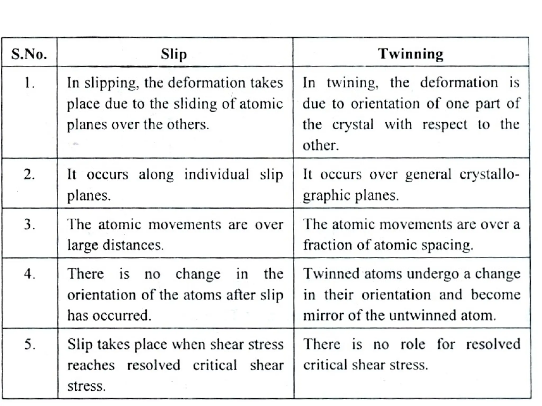
Slip
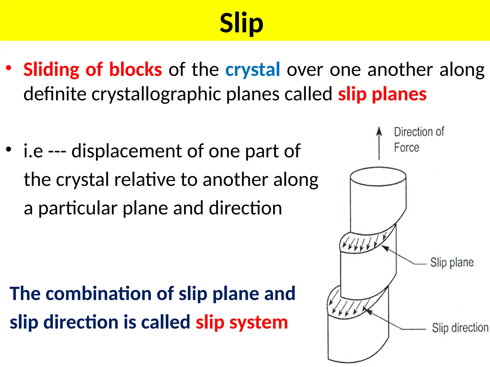
• Sliding ofblocks of the crystal over one another along
definite crystallographic planes called slip planes
• i.e --- displacement of one part of
the crystal relative to another along
a particular plane and direction
The combination of slip plane and
slip direction is called slip system
7.
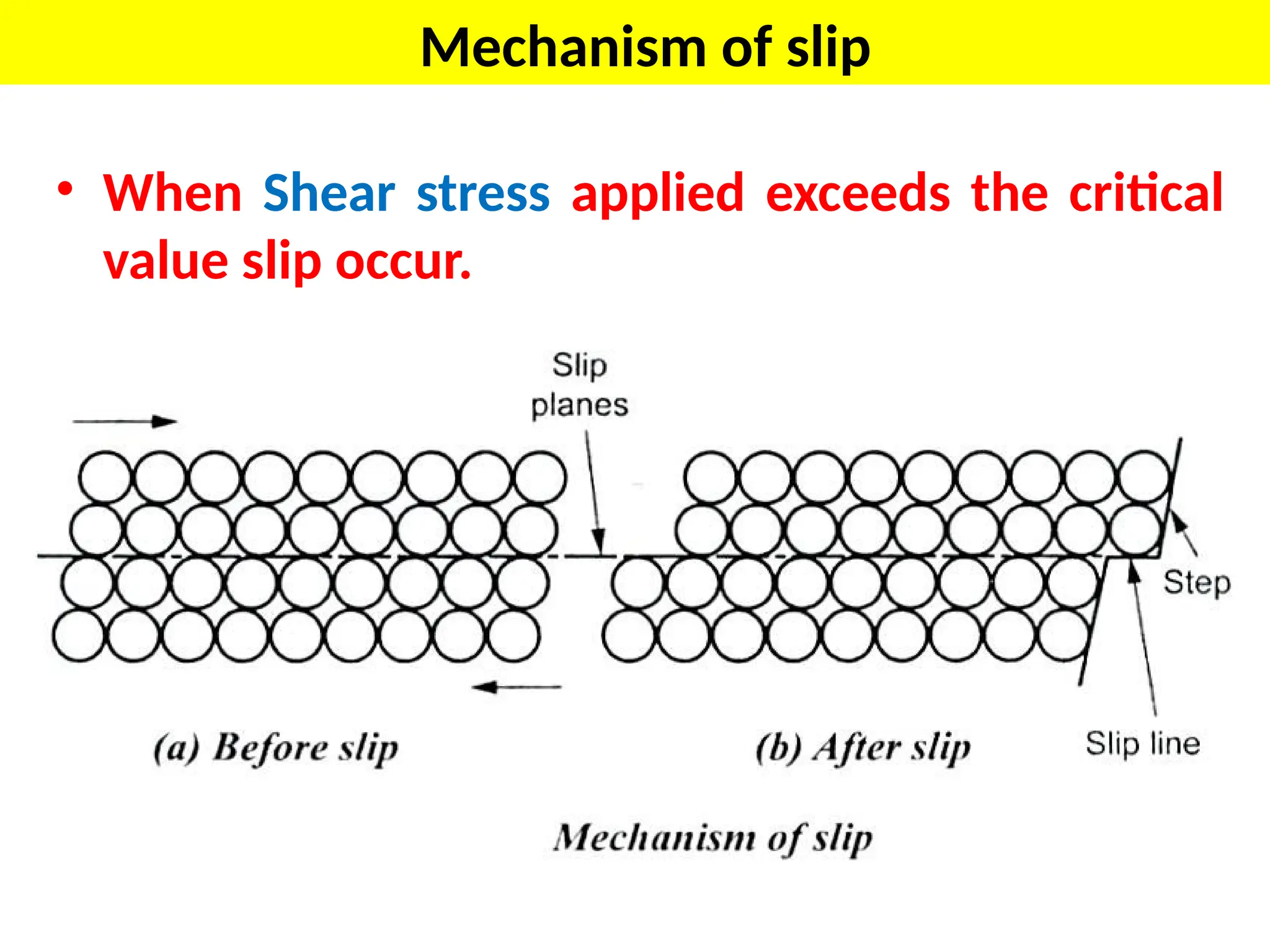
Mechanism of slip
•When Shear stress applied exceeds the critical
value slip occur.
8.
TWINNING
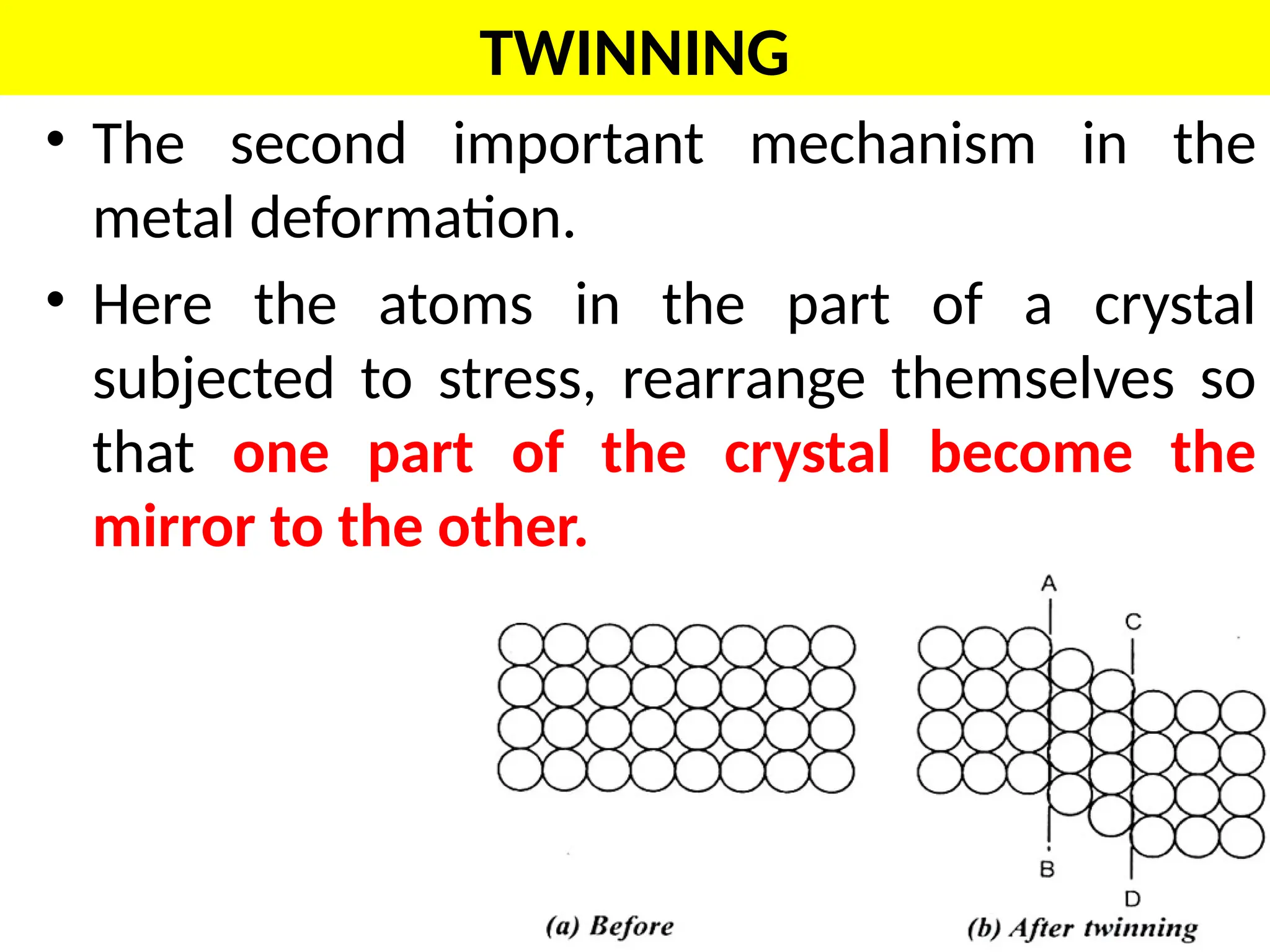
• The secondimportant mechanism in the
metal deformation.
• Here the atoms in the part of a crystal
subjected to stress, rearrange themselves so
that one part of the crystal become the
mirror to the other.
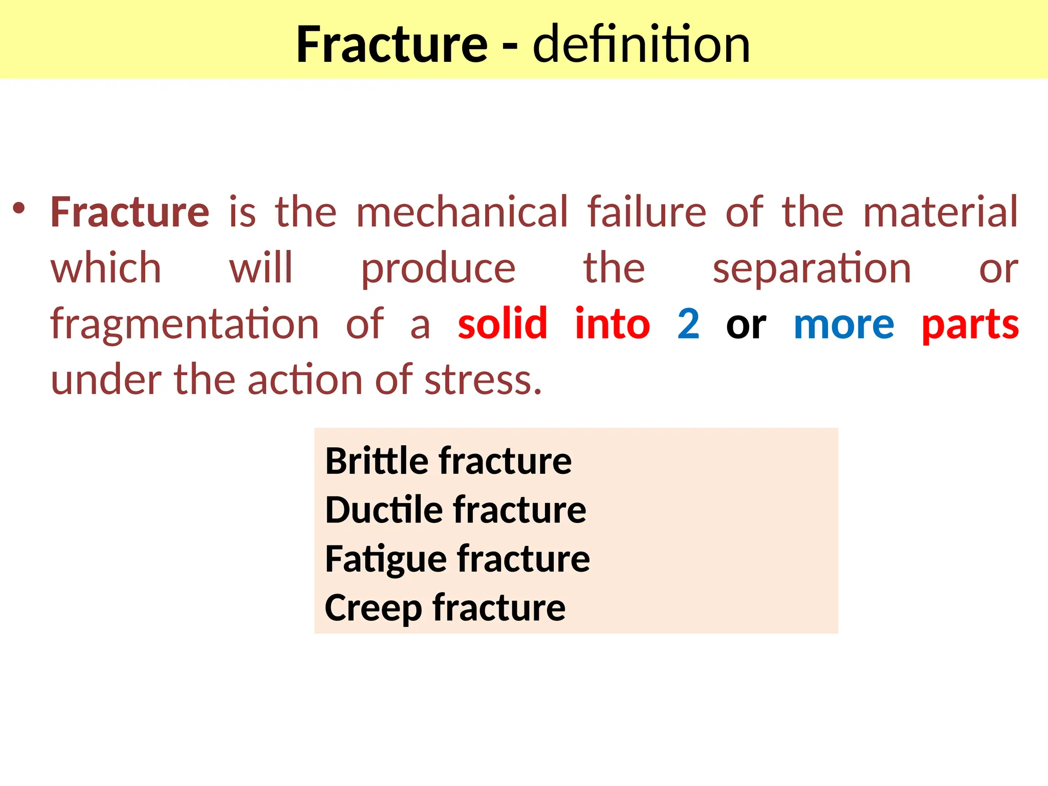
Fracture - definition
•Fracture is the mechanical failure of the material
which will produce the separation or
fragmentation of a solid into 2 or more parts
under the action of stress.
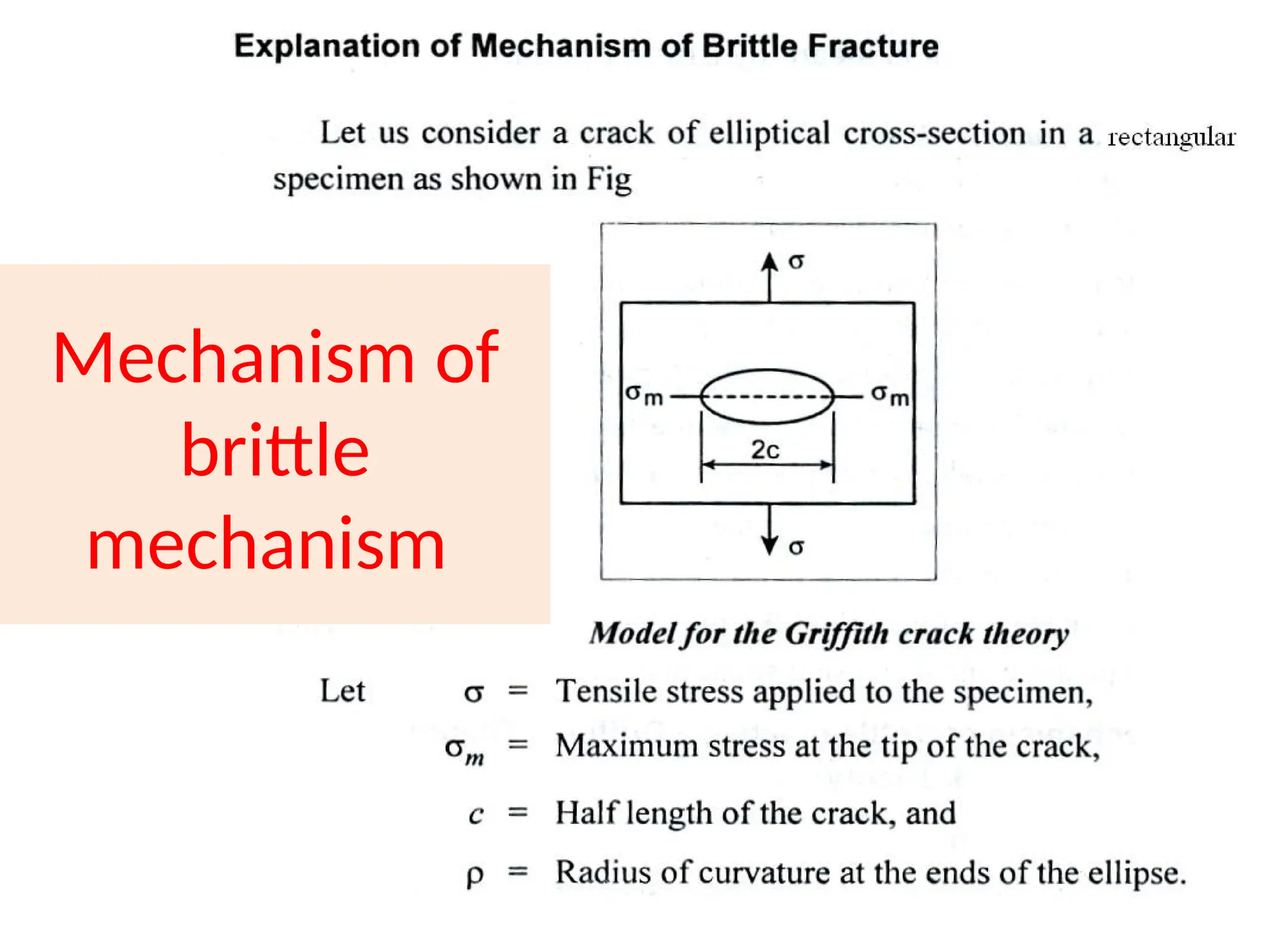
Brittle fracture
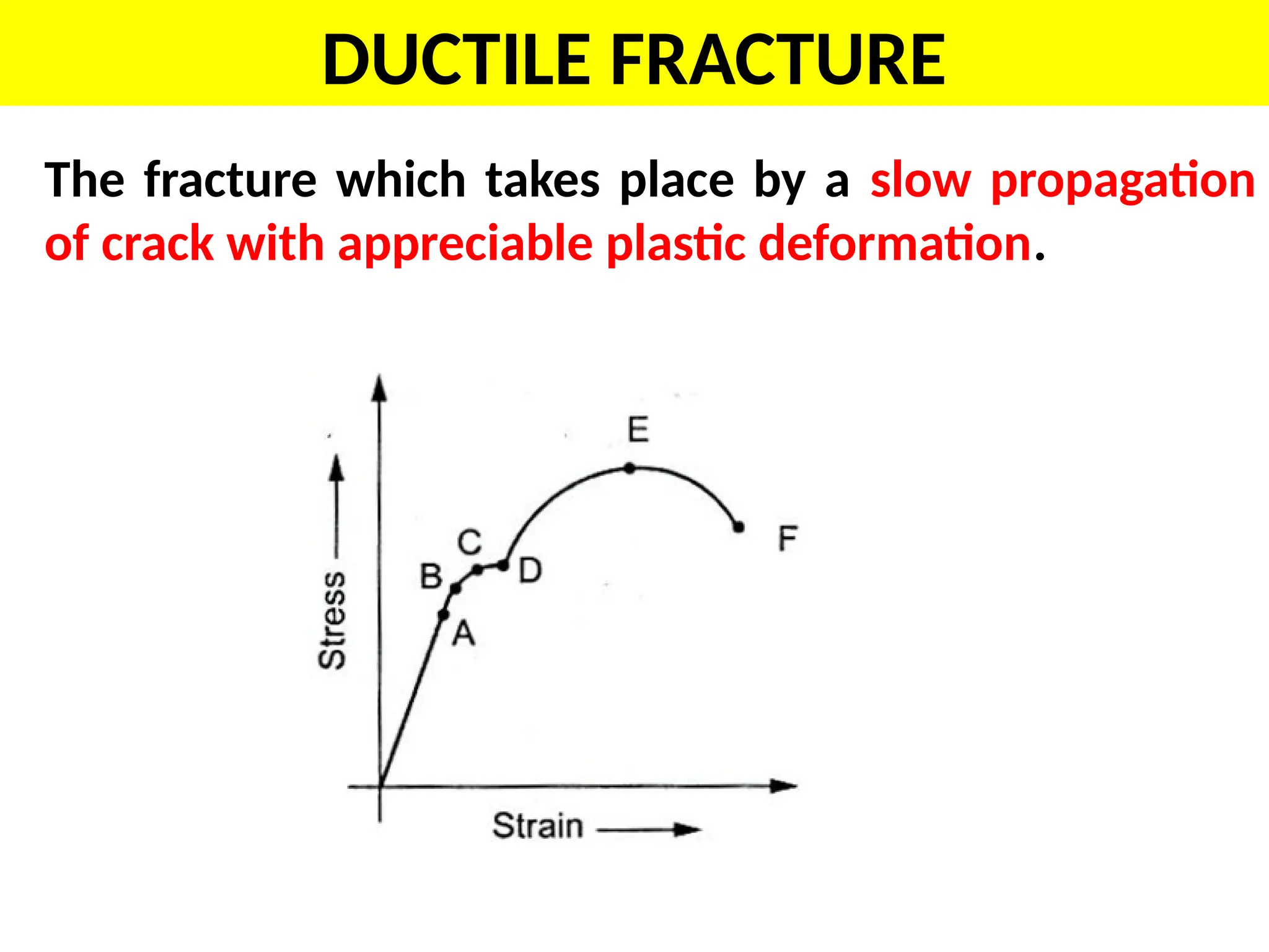
Ductile fracture
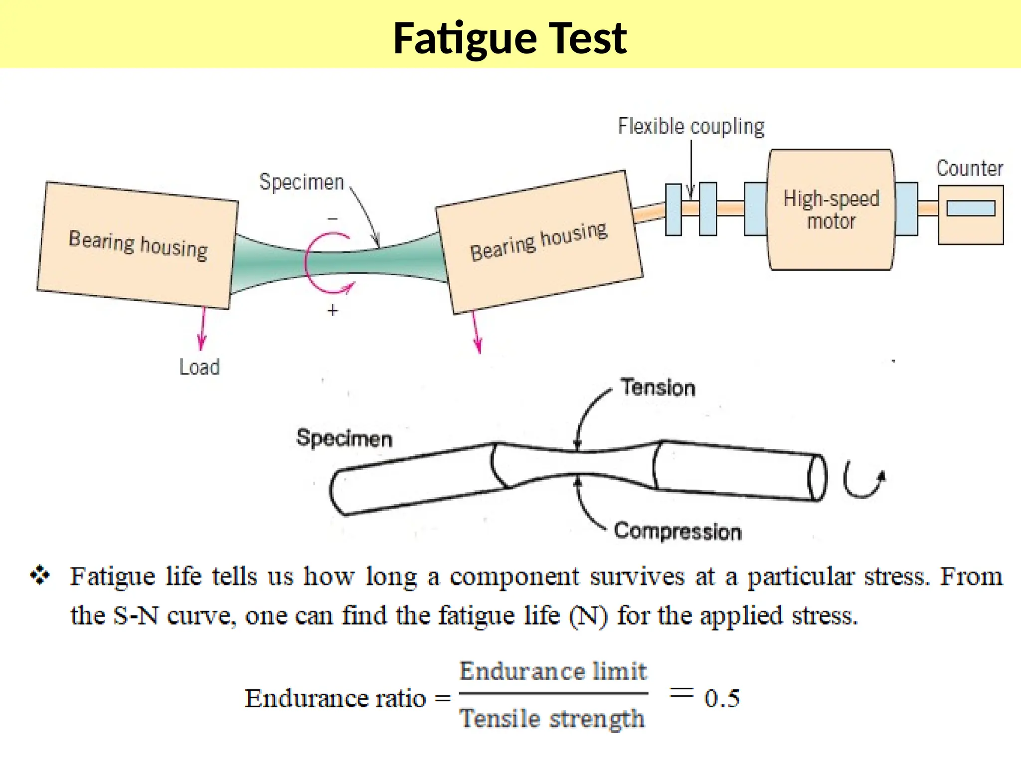
Fatigue fracture
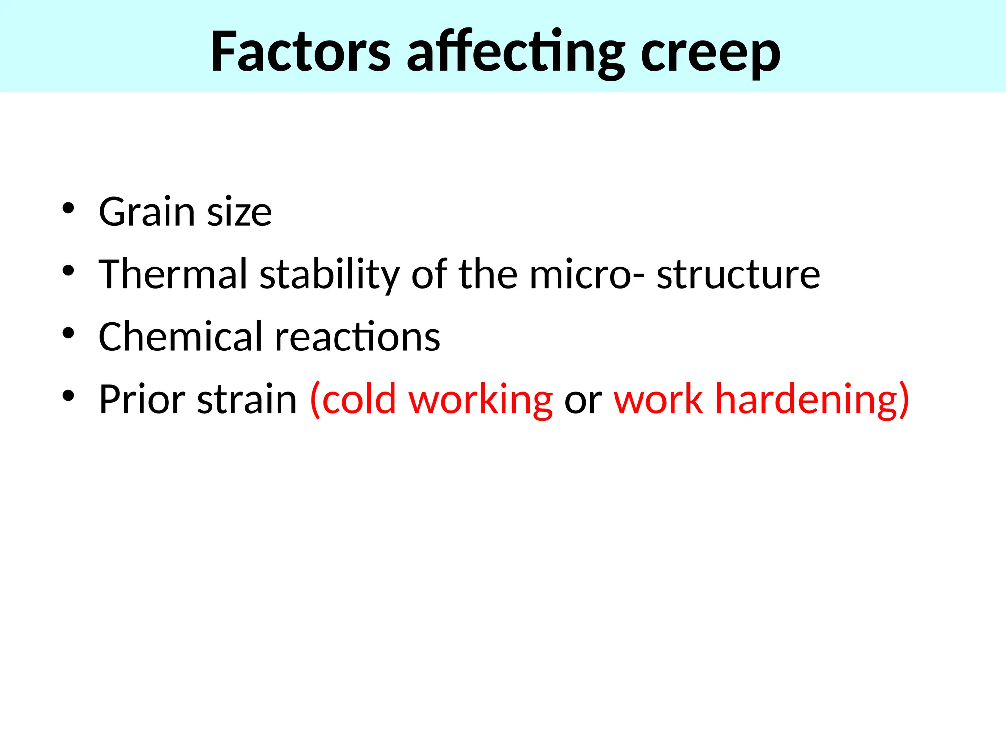
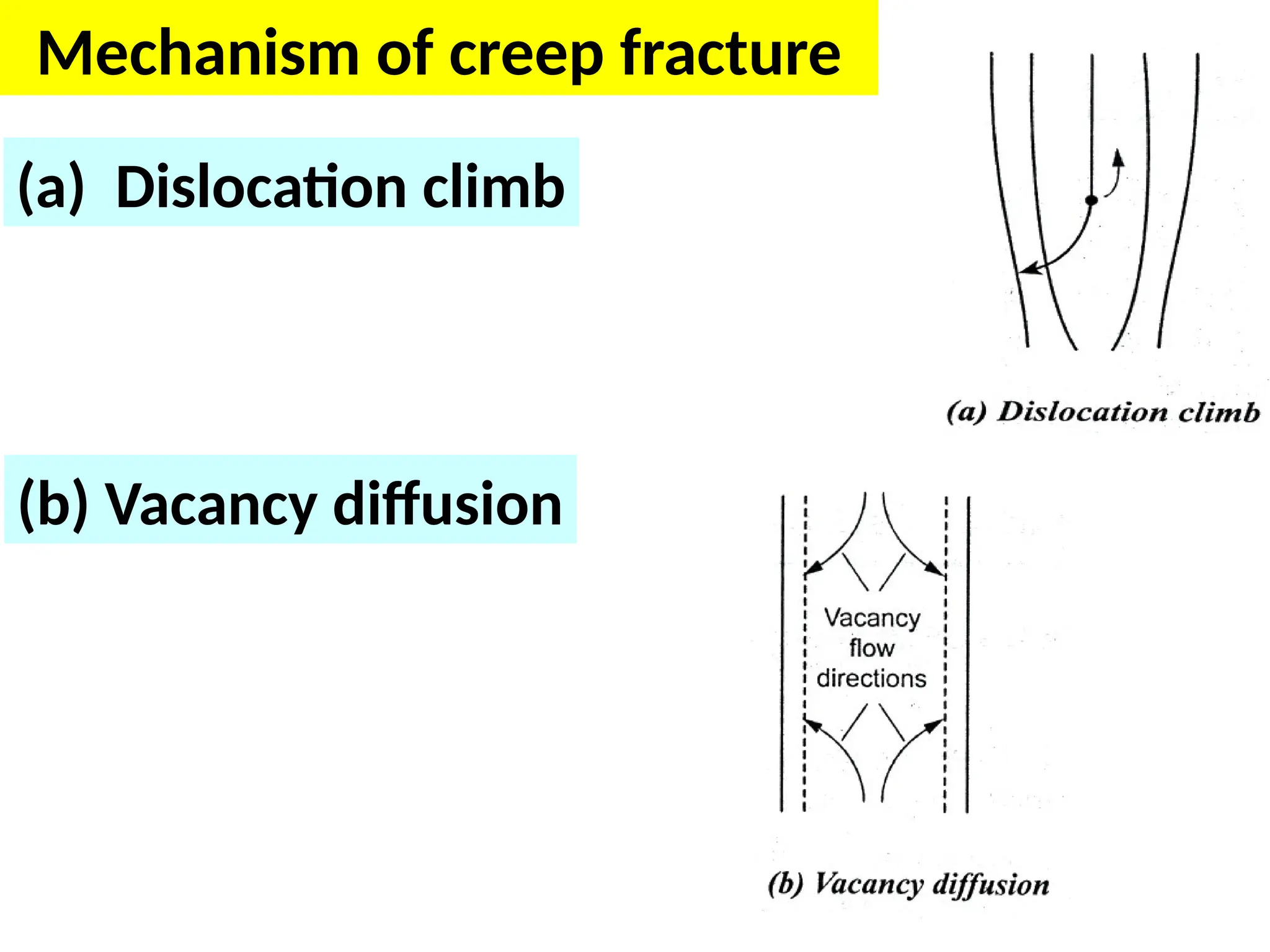
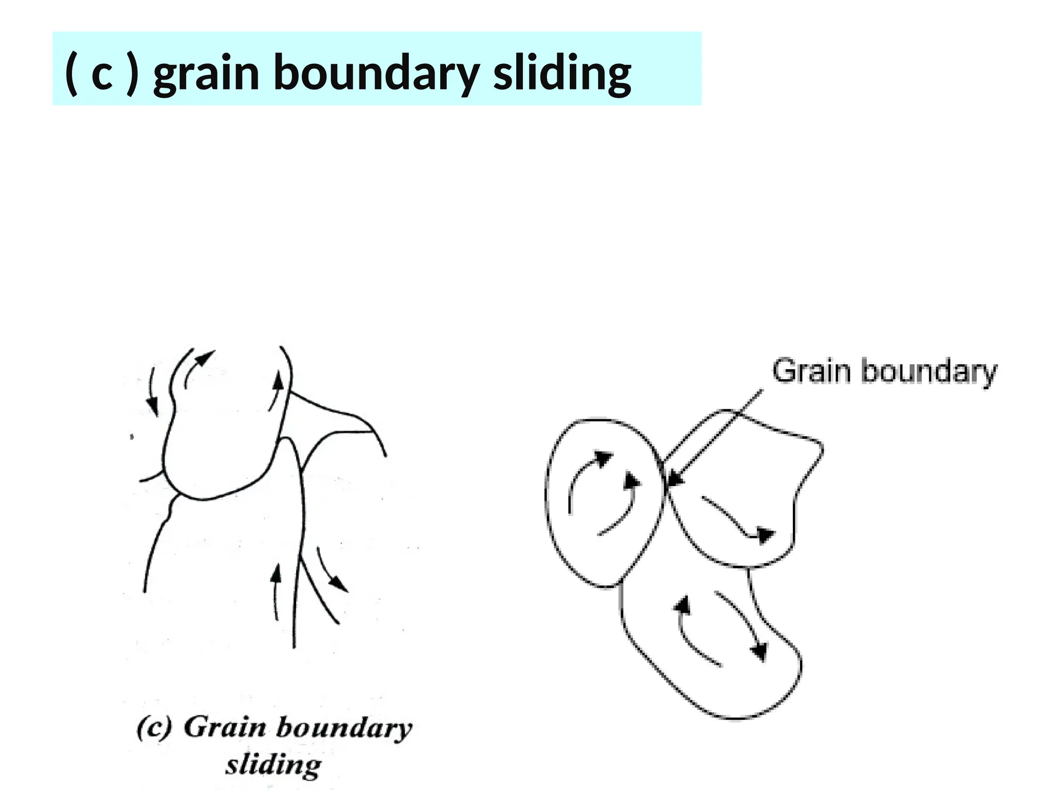
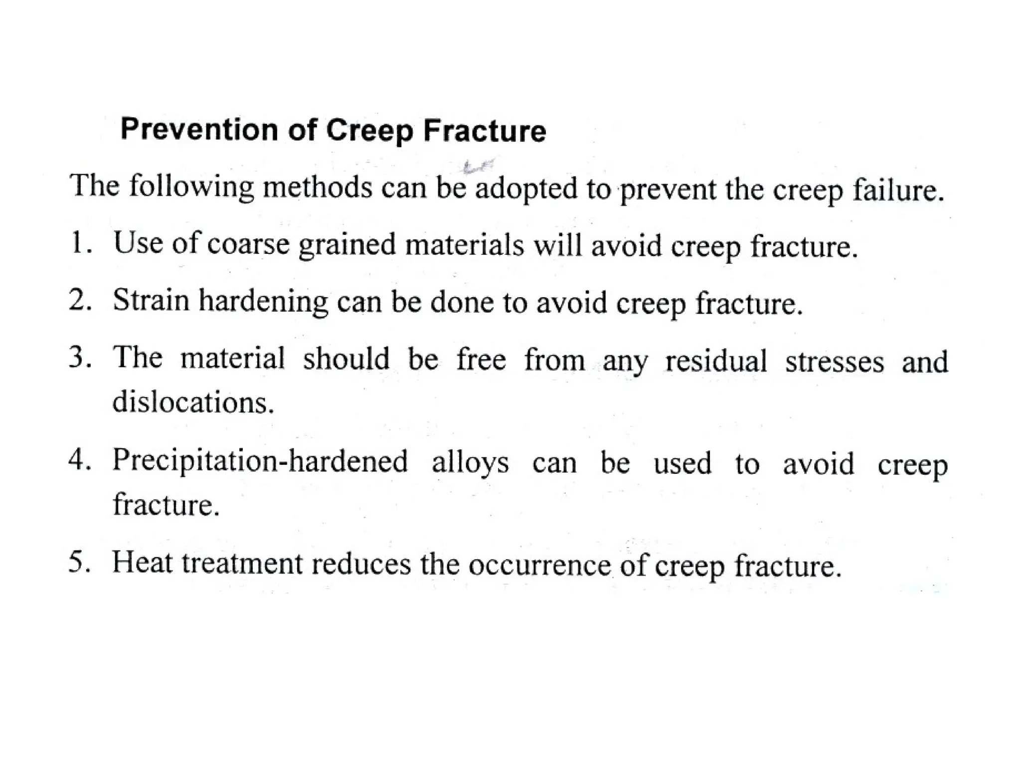
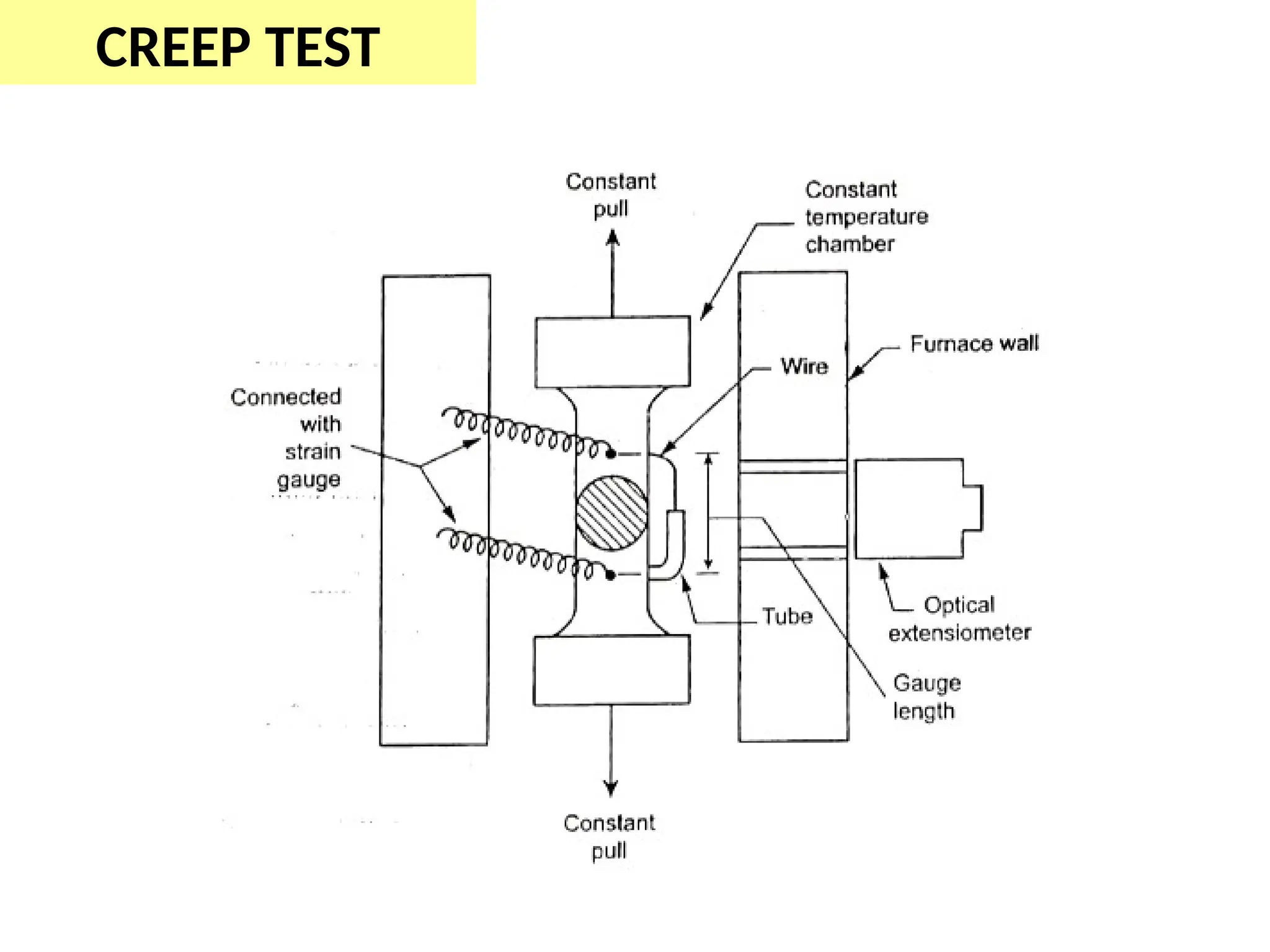
Creep fracture
12.
Brittle fracture
• Itsa fracture which takes place by the rapid
propagation of crack with a negligible
deformation.
• Mostly amorphous material like glasses
having this kind of fractures.
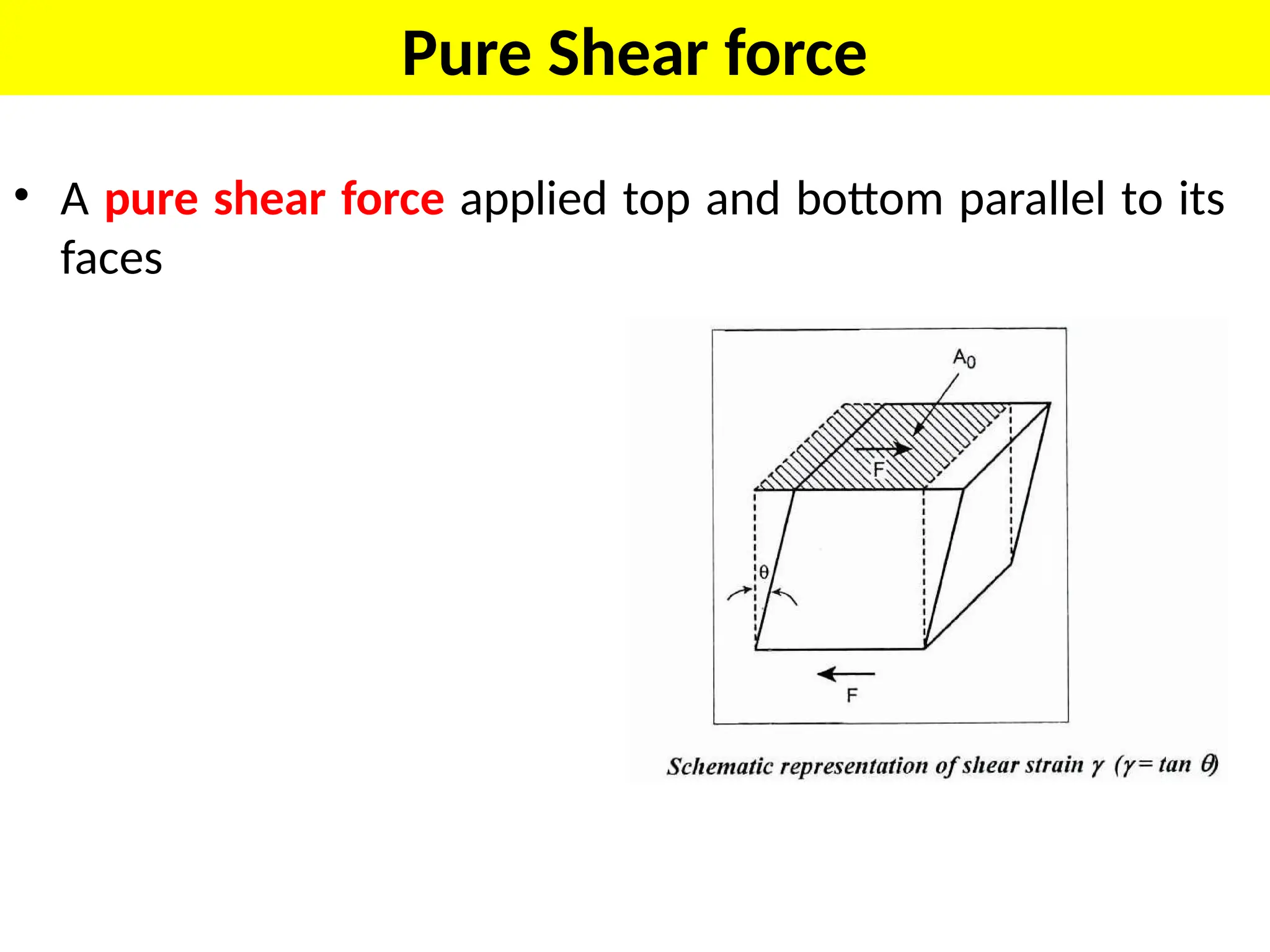
Pure Shear force
•A pure shear force applied top and bottom parallel to its
faces
48.
.
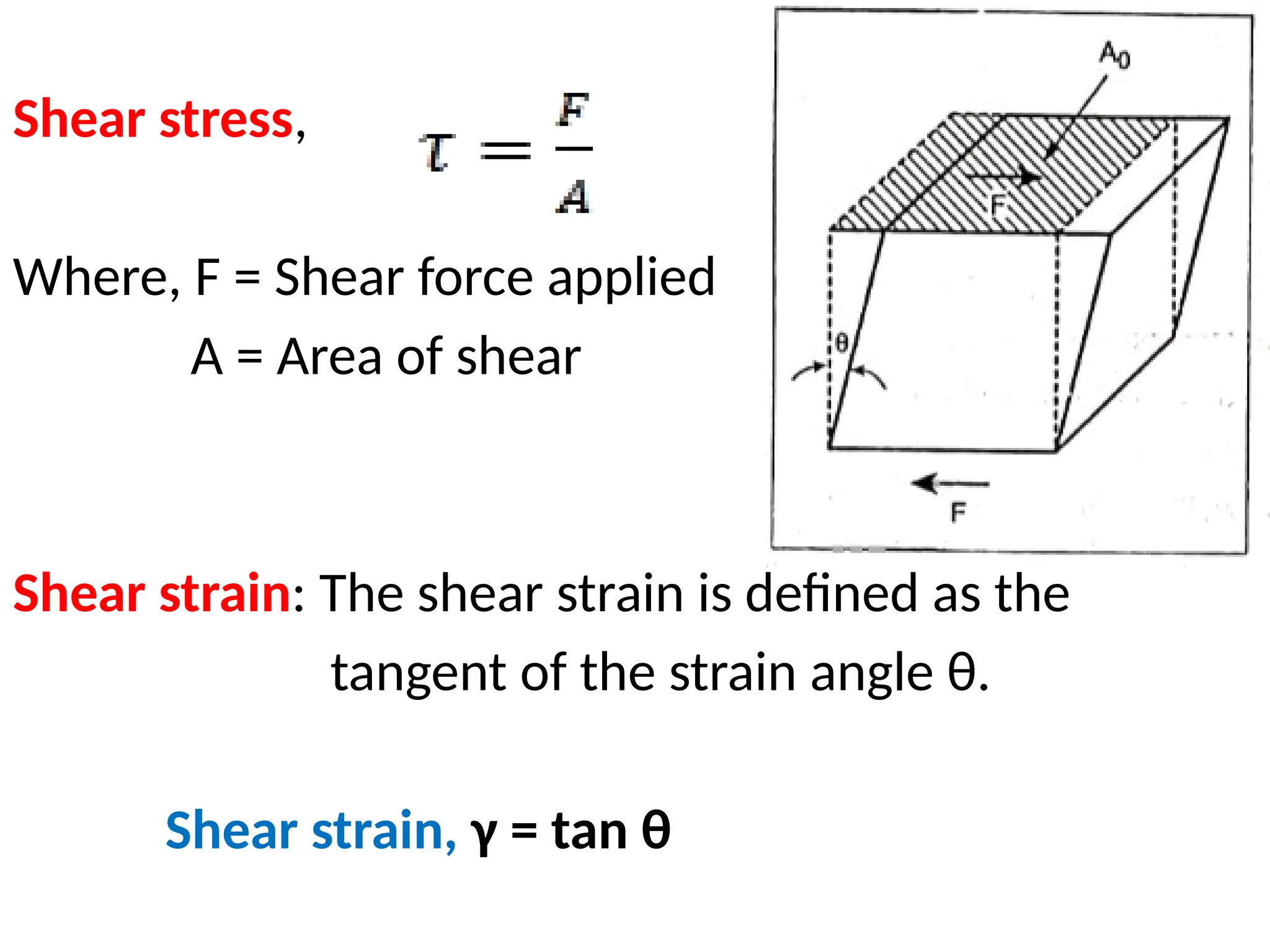
Shear stress,
Where, F= Shear force applied
A = Area of shear
Shear strain: The shear strain is defined as the
tangent of the strain angle θ.
Shear strain, γ = tan θ
49.
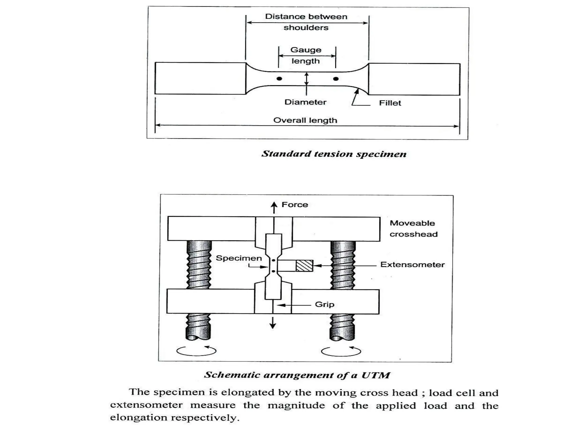
Limitations of sheartest
• Need attachment with UTM machine .
• Material at last gets bend
• So we will get the bending stress also, not the
pure shear type.
• Very difficult in processing
50.
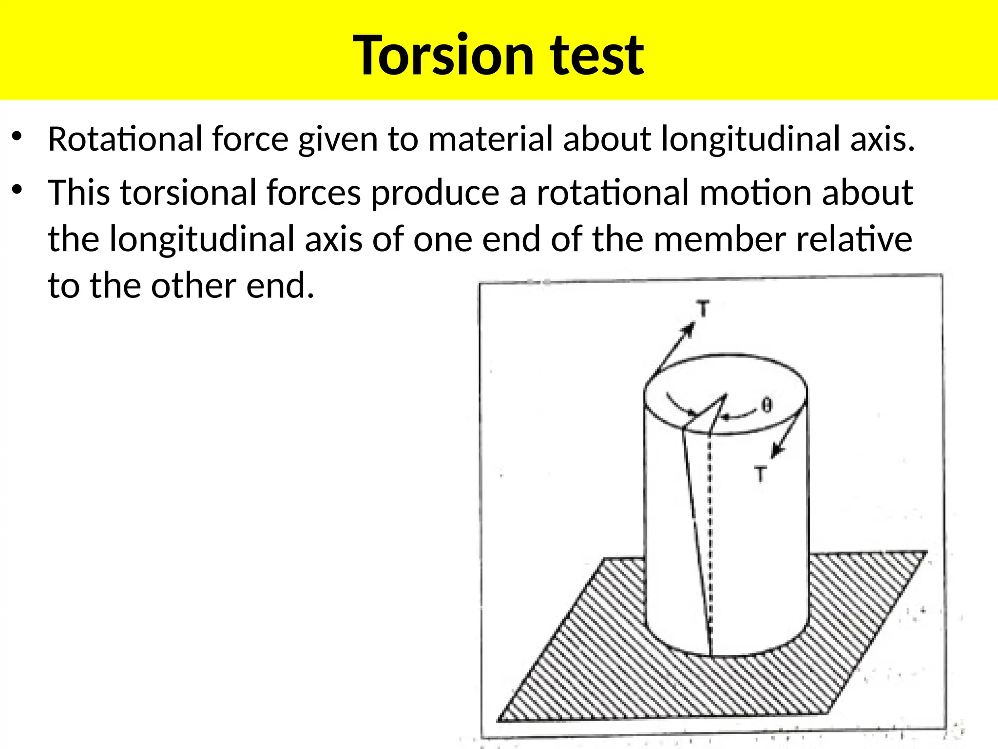
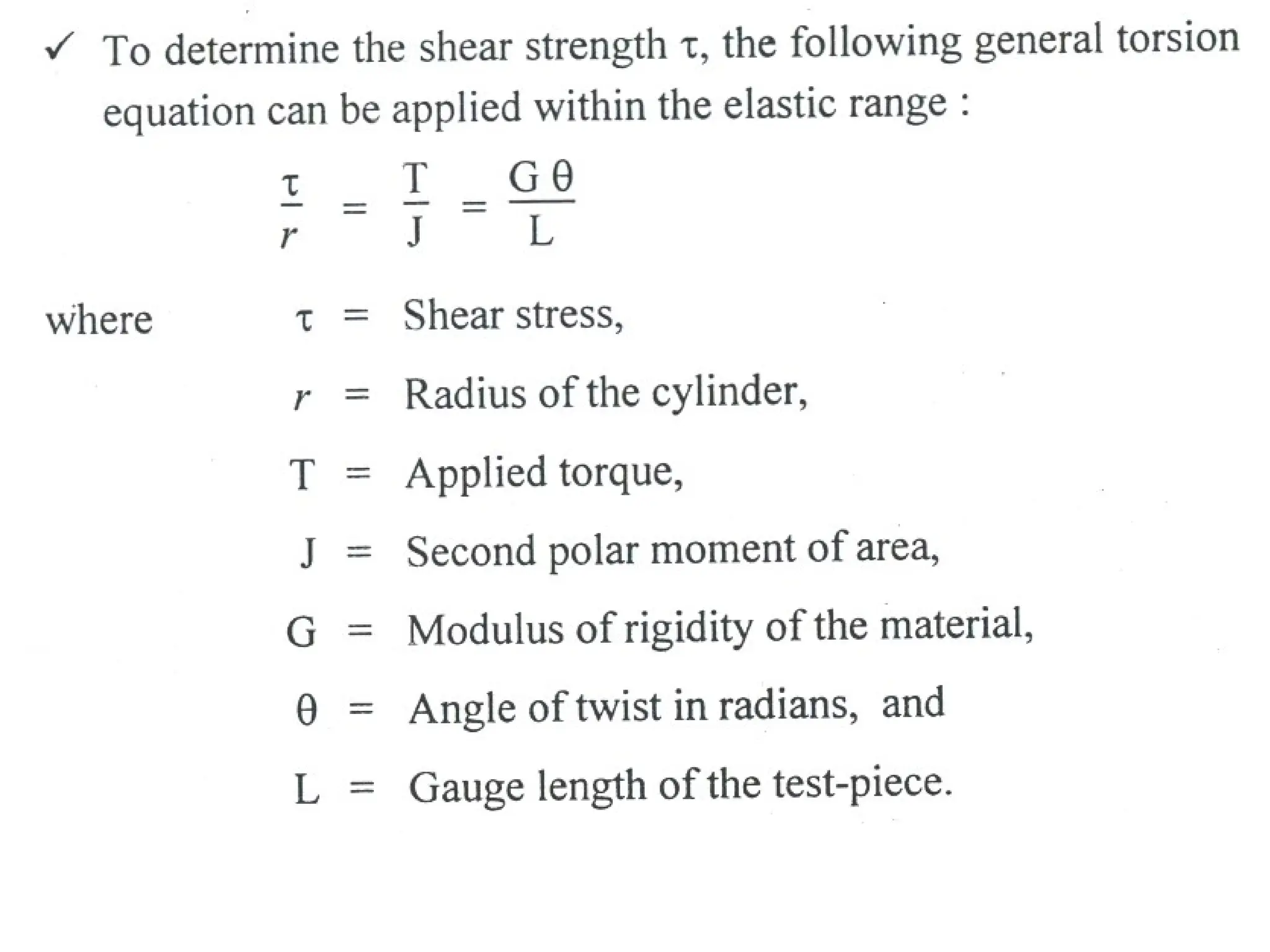
Torsion test
• Rotationalforce given to material about longitudinal axis.
• This torsional forces produce a rotational motion about
the longitudinal axis of one end of the member relative
to the other end.
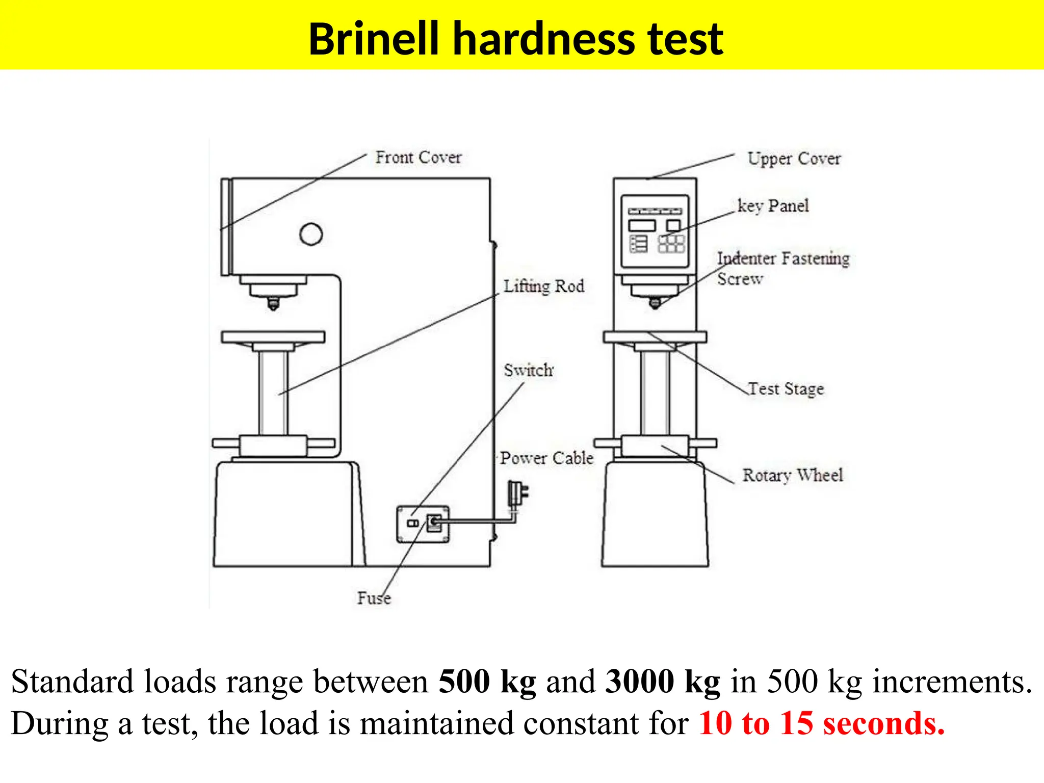
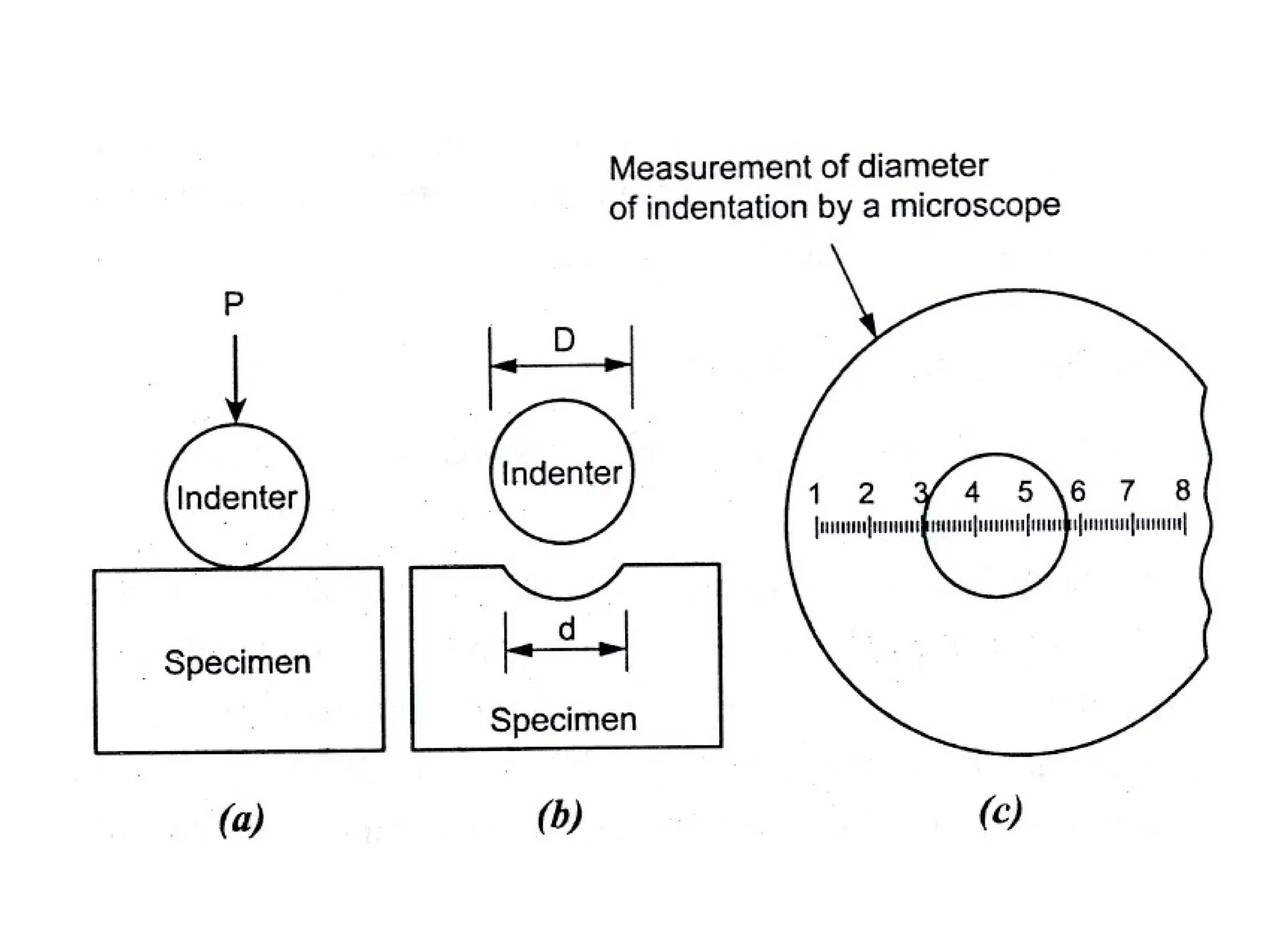
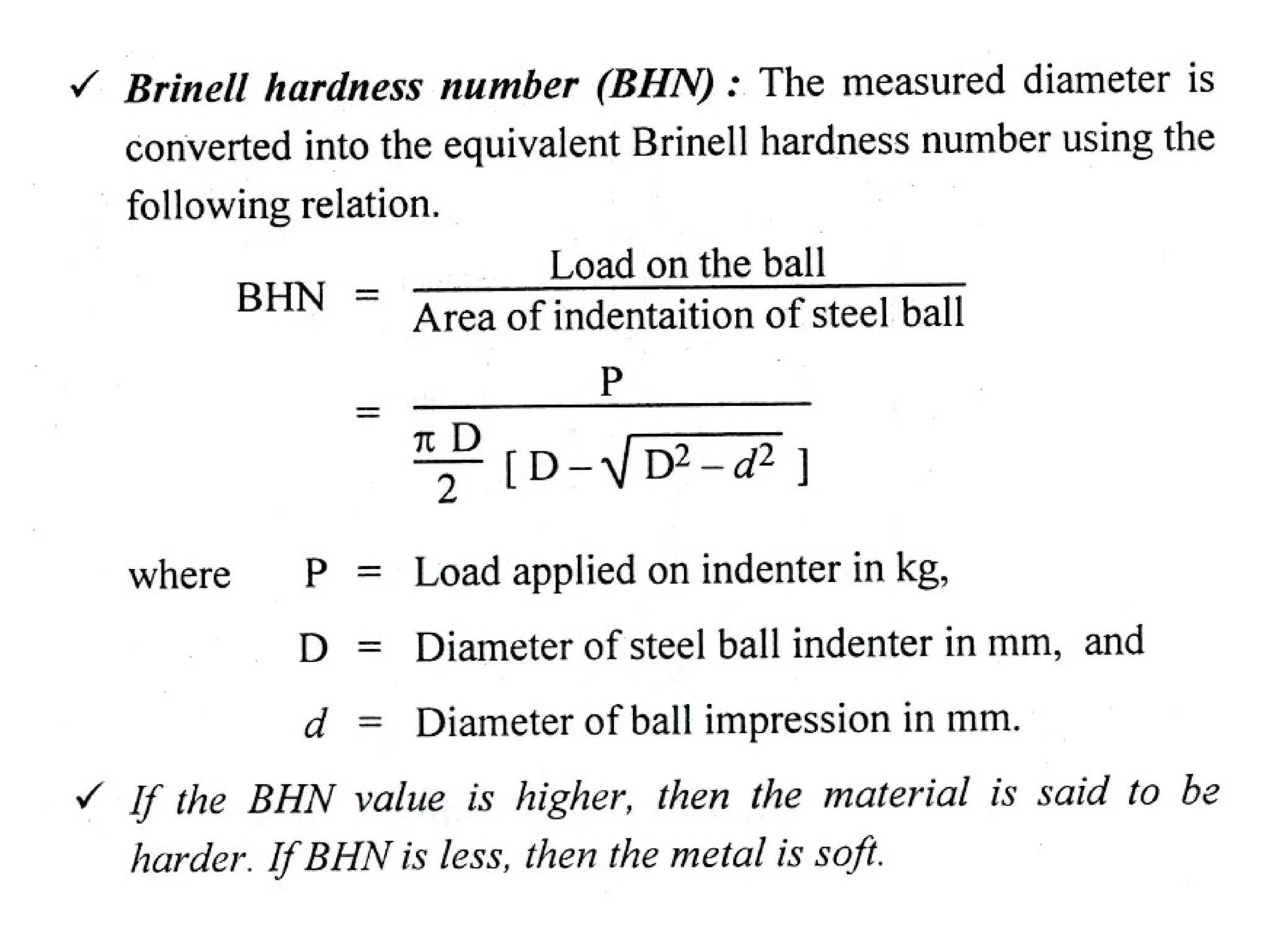
Brinell hardness test
Standardloads range between 500 kg and 3000 kg in 500 kg increments.
During a test, the load is maintained constant for 10 to 15 seconds.
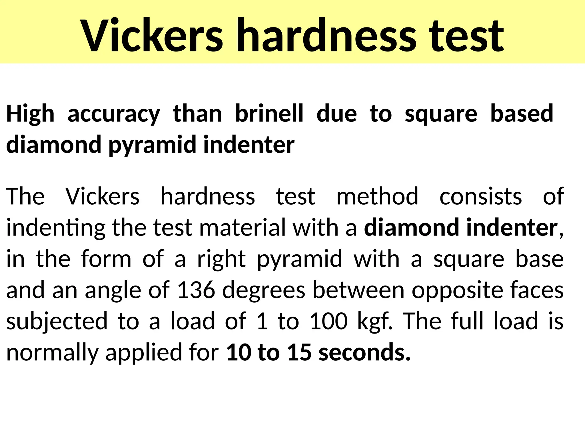
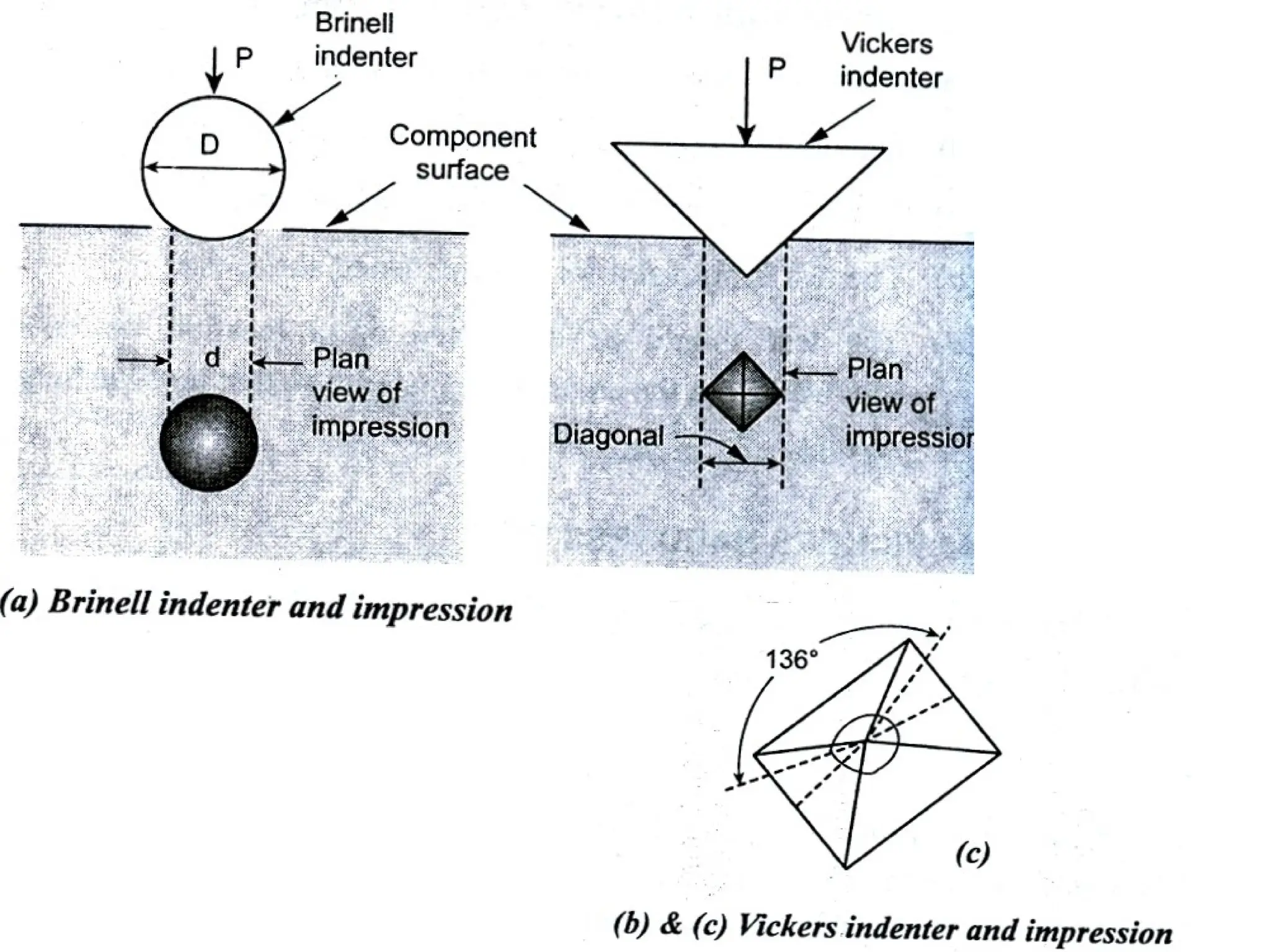
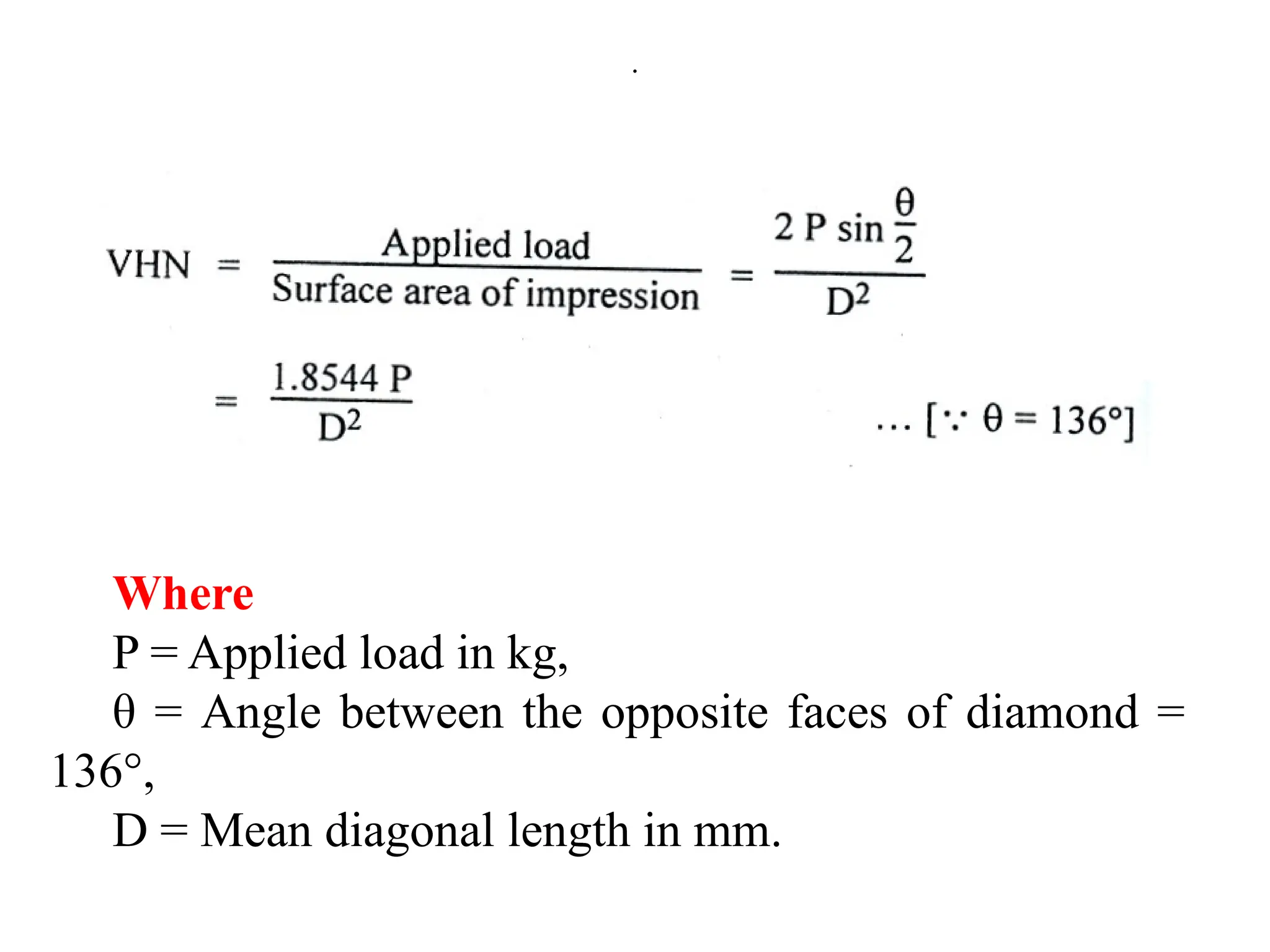
Vickers hardness test
Highaccuracy than brinell due to square based
diamond pyramid indenter
The Vickers hardness test method consists of
indenting the test material with a diamond indenter,
in the form of a right pyramid with a square base
and an angle of 136 degrees between opposite faces
subjected to a load of 1 to 100 kgf. The full load is
normally applied for 10 to 15 seconds.
.
Where
P = Appliedload in kg,
θ = Angle between the opposite faces of diamond =
136°,
D = Mean diagonal length in mm.
59.
Advantages
• The diagonalsof the square indentation can be measured
more accurately than the diameters of the circles.
• This method is suitable for hard materials as well as for soft
materials.
• The Vickers indenter is capable of giving geometrically
similar impression with different loads. Thus, the hardness
number is independent of the load applied.
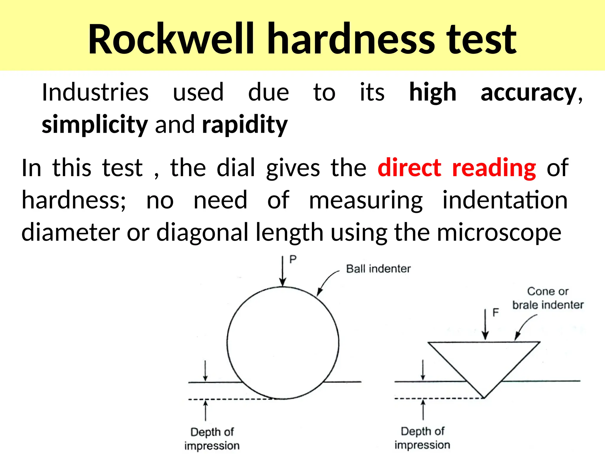
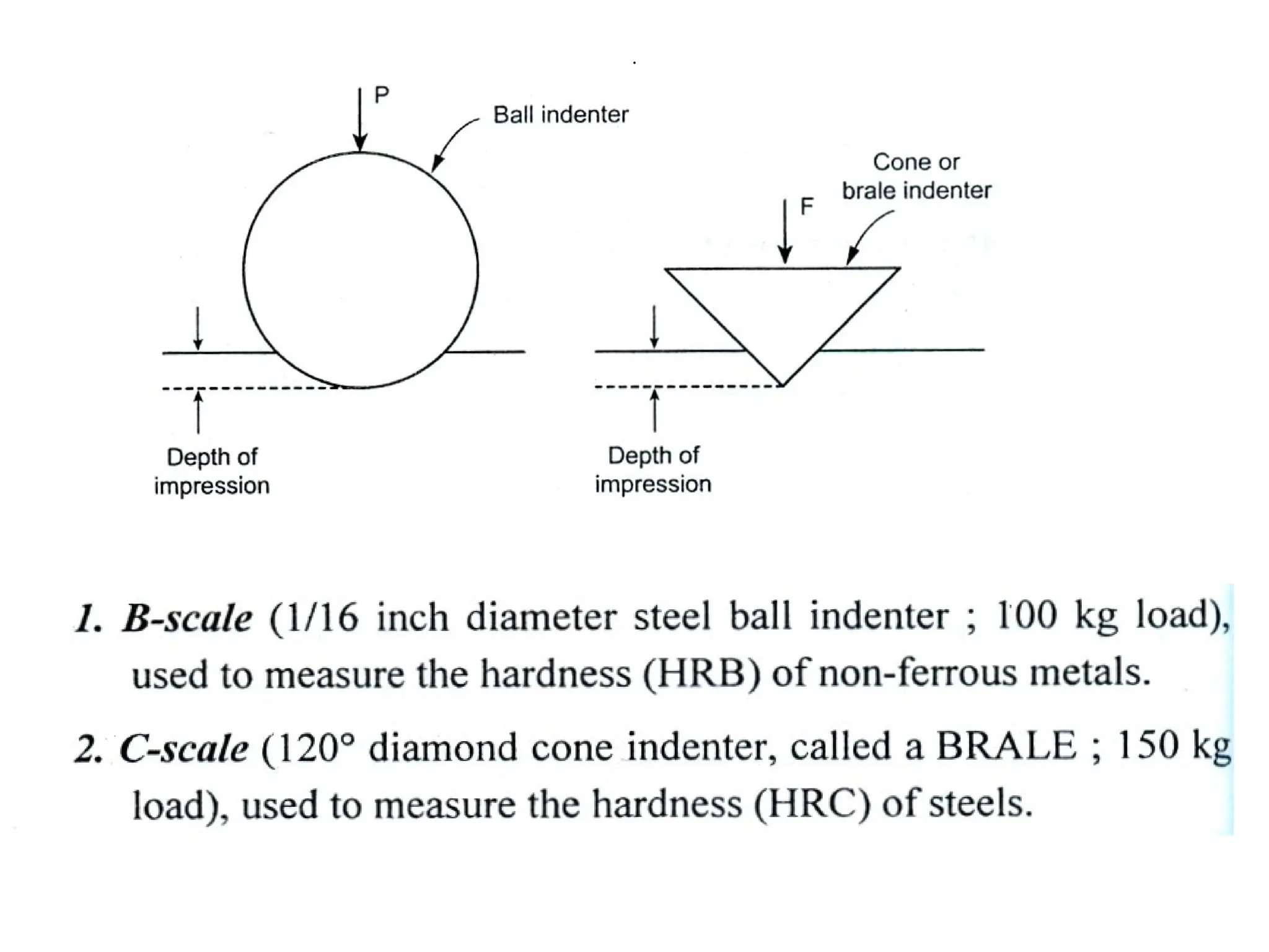
Rockwell hardness test
Industriesused due to its high accuracy,
simplicity and rapidity
In this test , the dial gives the direct reading of
hardness; no need of measuring indentation
diameter or diagonal length using the microscope
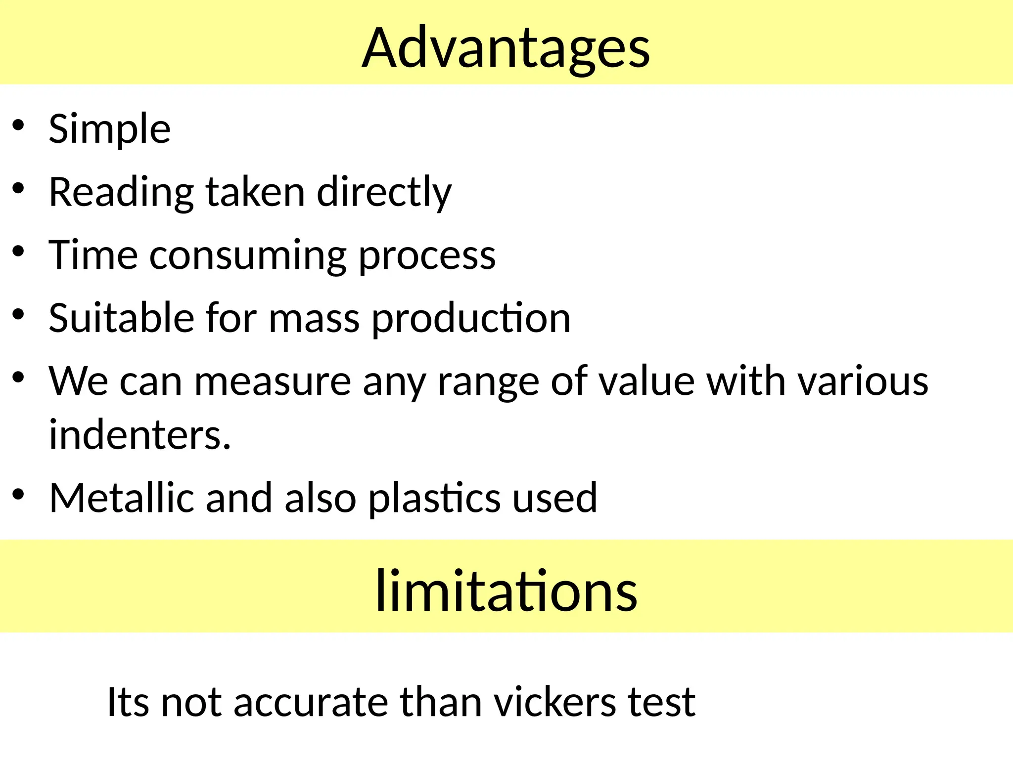
Advantages
• Simple
• Readingtaken directly
• Time consuming process
• Suitable for mass production
• We can measure any range of value with various
indenters.
• Metallic and also plastics used
limitations
Its not accurate than vickers test
64.
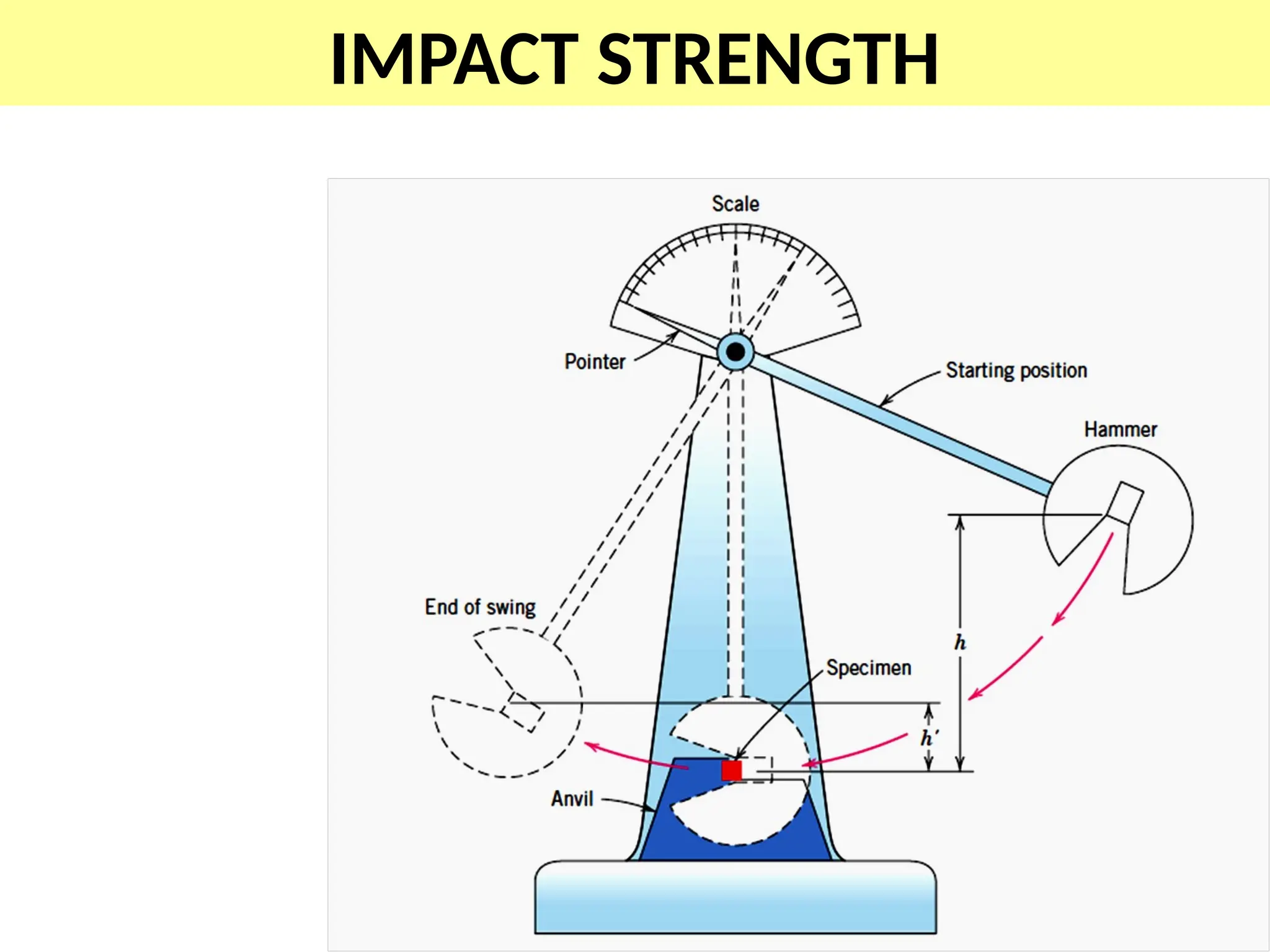
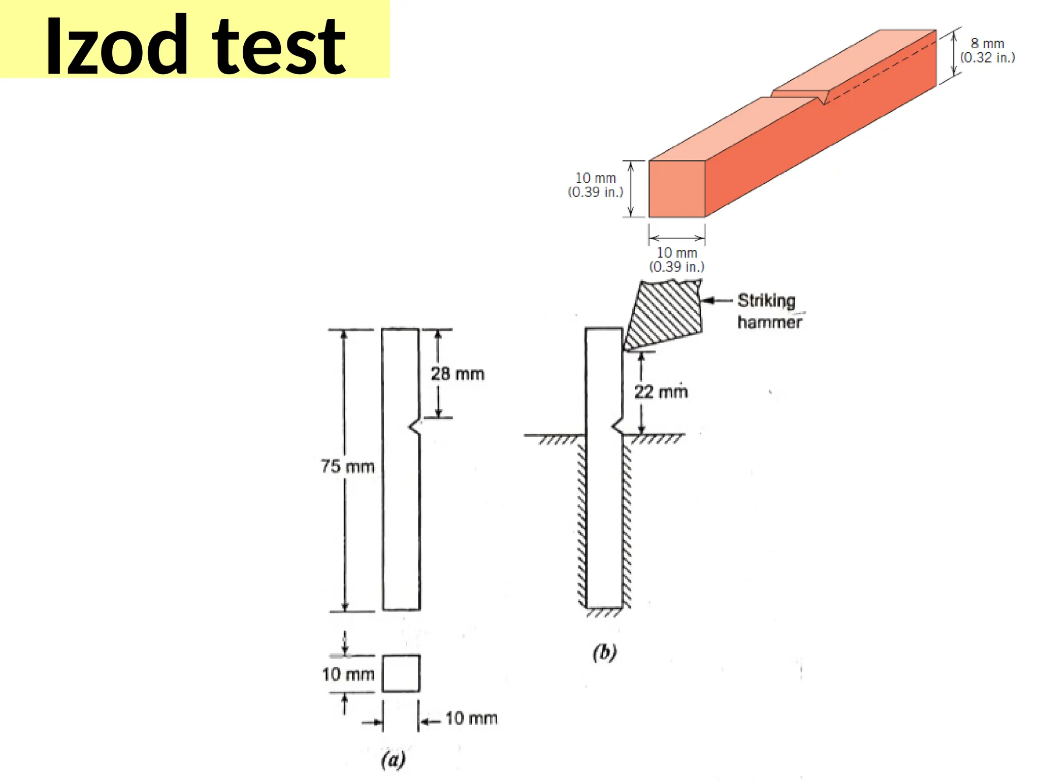
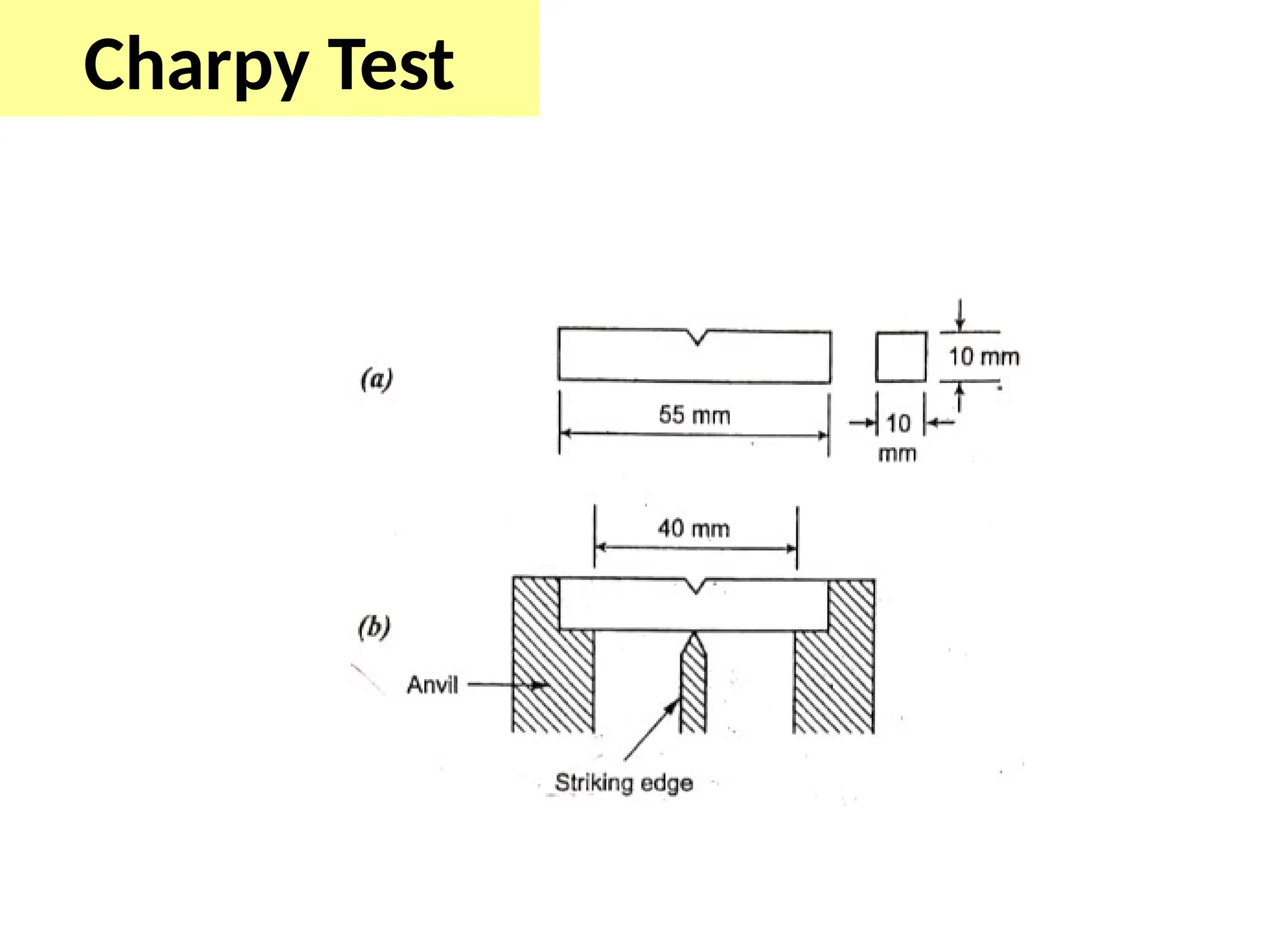
IMPACT TEST-
TO STUDYTHE BEHAVIOUR OF THE MATERIAL UNDER SUDDEN LOAD
IZOD TEST
CHARPY TEST