Downloaded 196 times
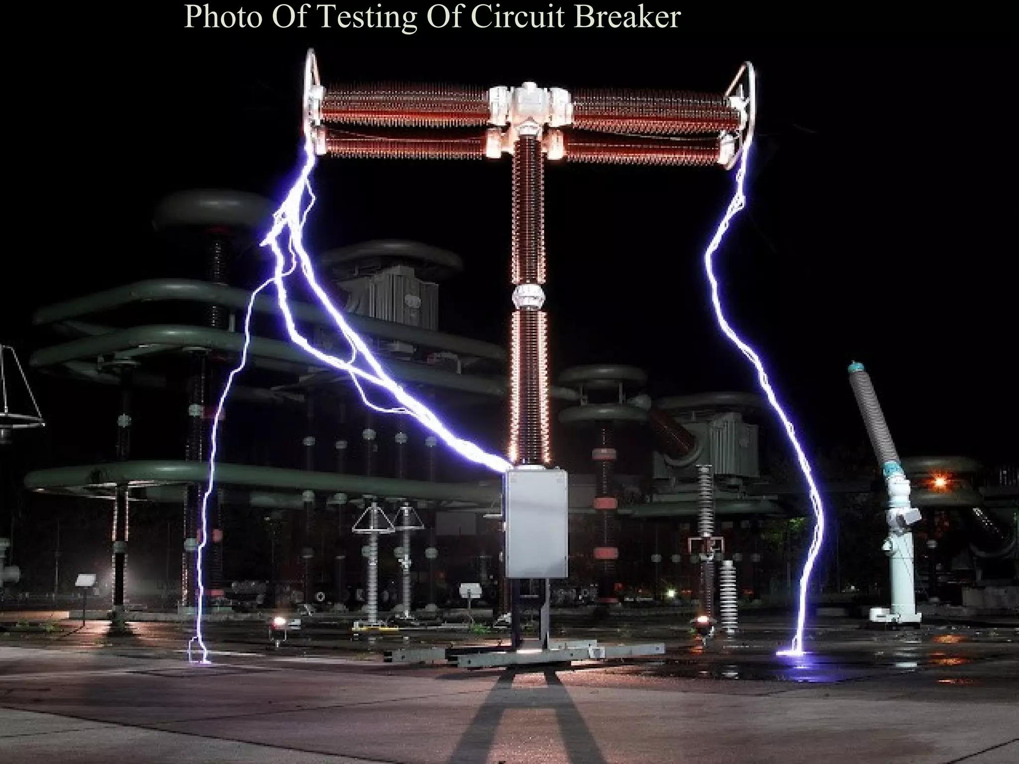


Circuit breaker testing is necessary to verify their performance under normal and abnormal conditions. There are two main types of tests: type tests to prove design features and quality, and routine tests to check for defects. Routine tests include mechanical endurance, thermal, dielectric, short circuit, and measurement of resistance tests. Proper preparation and equipment such as a short circuit generator, transformer, and measuring instruments are required to perform circuit breaker testing.