امتحان جهد عالي 2015-2016
•
1 like•95 views

This document contains a 3-part exam on high voltage engineering. Part 1 contains 3 questions, the first on measuring HVAC peak value and performing an accelerated aging test on a bushing. The second concerns generating HVDC using a Greinacher cascade circuit and a basic rectifier circuit. The third addresses impulse voltage generation and designing a 5-stage Marx generator. Part 2 contains 3 questions, two on RC and RLC circuits applied to DC sources, and one on flash protection boundaries for live busbars. Part 3 requests calculations regarding voltage regulation, ripple, and output of a Cockcroft-Walton circuit, as well as the design of a DC voltage doubling circuit.
![3. A ten. stage Cockraft-Walton circuit has all capacitors of 0.06 (J-F. The peak value
secondary voltage of the supply transformer is 100 kYat a frequency of 150 Hz. If the load
current is 1 mA, determine (i) voltage regulation (ii) the ripple (Hi) the optimum number
of stages for maximum output voltage (iv) the maximum output voltage. (5 Mark.')
Question 3 (20 Marks):
----- -- ------ - ---,------- -- ~---
1. The working principles of single-stage circuits for impulse voltage generation. (5Marks)
2. A 5-stage impulse generator after Marx circuit is to be designed for an impulse voltage of
0= 1 MV. A single-phase transformer ofr.m.s output of u= 175 kV is available to supply
the following arrangement. As impulse capacitances, capacitors of C= 50 nF will be used.
For R~ and Rd resistances with the following values are available.
R = 40 n, R = 80 n, and R = 1.3 ill
a) What is the value of the utilization factor of the generator? What is the peak inverse
voltage of the rectifier used for charging the impulse generator?
b) What values have Cs, Re, R, per stage by a maximum ratio Re/Rd for the utilization
factor calculated in point "a".
c) Calculate T; ITr of the generated impulse voltage [use kl= 0.73 & ka = 2.96].
elements of the following circuit
diagram are to be treated as ideal.
(5 Mark.')
lJel Rl
b f.
1UT
r
1id,
Rl C2
Udc
[I :::::...
3. A high voltage d.e. doubling circuit
(after Greinacher) for 600 kV terminal
voltage at no-load is to be designed for
a Practical Accelerator. All the circuit
a) Sketch the fundamental waveforms of the voltages UT, Uei and Ua-. The stationary
conditions under the assumptions idc=Constant and Cl=C2.
b) What should be the nominal rated voltage of the condensers Cl and C2? What is the
peak value of the reverse voltage of the rectifiers? For which rated voltage must be
H.V. transformer be ordered.
c) For Cl = C2 = 0.01 JlF and idc= 4 mA, UT= 100 sin (314 t) kV, calculate the maximum
and minimum output voltage. Consider equal voltage drops "~Uc1=~Uc2".
(10 Mark.")
Dr. Eng. Mohamed ELADA WY
Page 2
/](data:image/gif;base64,R0lGODlhAQABAIAAAAAAAP///yH5BAEAAAAALAAAAAABAAEAAAIBRAA7)
Recommended
More Related Content
What's hot
What's hot (19)
Similar to امتحان جهد عالي 2015-2016
Similar to امتحان جهد عالي 2015-2016 (20)
More from eslam elfayoumy
More from eslam elfayoumy (10)
Recently uploaded
Recently uploaded (20)
امتحان جهد عالي 2015-2016
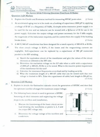
- 1. (,'~t:Mansoura University 2015-2016 High-Voh'g' Engineering (EEZ316) _-: . f!is"')-eP" Faculty of Engineering 3rd year Fmal Term Exam (rart.1) . ~ : I , Time Allowed: 1.5 Hours'-:::::;';~~:"Electrical Engineering Dept. Sunday 17-1-2016 ••.• Pis. Answer All the Following Questions (Total Score 50 Marks) Question 1 (20 Marks): 1. Explain the Chubb and Fortescue method for measuring HVAC peak value. (5 Marks) 2. An accelerated aging test is to be made on a bushing of capacitance 2000 pF by applying a voltage of 15 kV at a frequency of 5.kHz. A simple series resonance power supply is to be used for the test and an inductor can be wound with a Q-factor of 14 for use in the power supply. Calculate the output voltage and power necessary for the 5 kHz supply, the magnitude of the inductance required, and the current from the supply if the bushing breaks down. (5 A1arks) 3. A 400 V/ 400 kV transformer has been designed for a rated capacity of 200 kVA at 50 Hz. The short circuit voltage is 15.6%; if the losses and the magnetizing currents are negligible. Self-capacitance can be replaced by a capacitance of 380 pF connected parallel to the HV winding. a) Sketch the equivalent circuit of the transformer and give the values of the circuit elements as referred to the HV side. b) Determine the excitation voltage on the LV side when a cable with a capacitance of 2800 pF at 400 kV, 50 Hz is to be tested. What is the reactive power requirement of the transformer for the test? c) Calculate the resonance frequencies atno-load and by loading as in b). d) What the maximum length of a 400 kV cable that can be tested such that over voltage is limited to 10%. Take the capacitance of cable/unit length is 150pF/m. (10 Mark.J) Question 2 (15 Marks): . 1. Explain in details the Greinacher cascade circuit for generation of HVDC and then find the optimum number of stages for maximum output voltage. (5 MarkJ) 2. The following basic circuit is used to generate a HVDe. Assuming all ideal elements and neglecting the voltage drops in the rectifiers and transformer, Discuss the functioning of the basic circuit on no- load showing the waveforms at points 1, 2, 3 and the output DC voltage u(t). I. 30---1 1---- -0----1 ---02 11. Determine the voltage ratings of the rectifiers and condensers. 1+----- 1I(r)----~ (5 Mark.l) Page 1 /
- 2. 3. A ten. stage Cockraft-Walton circuit has all capacitors of 0.06 (J-F. The peak value secondary voltage of the supply transformer is 100 kYat a frequency of 150 Hz. If the load current is 1 mA, determine (i) voltage regulation (ii) the ripple (Hi) the optimum number of stages for maximum output voltage (iv) the maximum output voltage. (5 Mark.') Question 3 (20 Marks): ----- -- ------ - ---,------- -- ~--- 1. The working principles of single-stage circuits for impulse voltage generation. (5Marks) 2. A 5-stage impulse generator after Marx circuit is to be designed for an impulse voltage of 0= 1 MV. A single-phase transformer ofr.m.s output of u= 175 kV is available to supply the following arrangement. As impulse capacitances, capacitors of C= 50 nF will be used. For R~ and Rd resistances with the following values are available. R = 40 n, R = 80 n, and R = 1.3 ill a) What is the value of the utilization factor of the generator? What is the peak inverse voltage of the rectifier used for charging the impulse generator? b) What values have Cs, Re, R, per stage by a maximum ratio Re/Rd for the utilization factor calculated in point "a". c) Calculate T; ITr of the generated impulse voltage [use kl= 0.73 & ka = 2.96]. elements of the following circuit diagram are to be treated as ideal. (5 Mark.') lJel Rl b f. 1UT r 1id, Rl C2 Udc [I :::::... 3. A high voltage d.e. doubling circuit (after Greinacher) for 600 kV terminal voltage at no-load is to be designed for a Practical Accelerator. All the circuit a) Sketch the fundamental waveforms of the voltages UT, Uei and Ua-. The stationary conditions under the assumptions idc=Constant and Cl=C2. b) What should be the nominal rated voltage of the condensers Cl and C2? What is the peak value of the reverse voltage of the rectifiers? For which rated voltage must be H.V. transformer be ordered. c) For Cl = C2 = 0.01 JlF and idc= 4 mA, UT= 100 sin (314 t) kV, calculate the maximum and minimum output voltage. Consider equal voltage drops "~Uc1=~Uc2". (10 Mark.") Dr. Eng. Mohamed ELADA WY Page 2 /
- 3. • . '.J.. ~"' • . J t .• : -"":.'" .•• •• I Mansoura University Term 1- Test High Voltage Part 2 - 1 naae Faculty of Engineering Test time for J!.arts 1 and 2 (3 hr's) EE2316 Electrical Eng, Dept. (3 ni Year) Dr. Mohamed Fawzi Kotb 2016 Question No. (1) [30 degrees] 1. Mark (True) or (False) (6 degrees): i i , a. HV long transmission lines creates Capacitance and stores energy in a magnetic field which proportional to the square of voltage. b. In the unearthred system earth fault on one line causes increasing voltage on the --- otlier tWolines anoleads to-insulation de2radation. c. When DC Source is applied to a series resistance and capacitor the current will start with a value of (VIR) and will exponentially increase with time.. d. When DC Source is applied to capacitor an impulse will be produced with the magnitude of (VC). e. Surge arrestors have very high inductance at normal voltage and very low inductance at SU)"2evoltaaes, f. The value of voltage wave refraction coefficient is (-1) when Overhead Transmission Line is opened and (2) when it is short circuited. 2. Draw sketches for TT & TN-C and TNS earthing system indicating the earth fault path? (9 degrees) 3. Explain different types of surge arrestors indicating the following: (6 degrees). v' Advantages and disadvantages. v The characteristic of each type with the aid of drawings. 4. Draw the connection and location of Surge arrestors used for the following: (9 degrees} a- Station b- Transmission line c- Distribution transformer Question No. (2) [12 degrees) 1. If de supply is applied to R-L-C circuit, state the relation between i(t) and t and draw its characteristics when: (4 degrees) a- Term (b) = 0 b- Term (b) is real value 2. For RC circuit is closed to a 40 Vde while the capacitor was initially charged to 30 volts, R = 500 n and C = 20 flF. (8 degrees) a- What is the final voltage of the capacitor after the "end" of the transient? b- Draw the relation between voltage and time. Question No. (3) [8 degrees] i. If Bus Bar has 30.000.0 ampere short circuit current, 400 volts, 3 phase system. Calculate the Flash Protection Boundary Distance in the following two eases and write your comments: a- Using non-current limiting circuit with clearing time is 5 cycles b- Using current limiting fuses with clearing time 0.5 cycle .Best Regards Page 1 of 1 /
- 4. 3. A ten. stage Cockraft-Walton circuit has all capacitors of 0.06· !J.F. The peak value secondary voltage of the supply transformer is 100 kVat a frequency of 150 Hz. If the load current is 1 mA, determine (i) voltage regulation (ii) the ripple (iii) the optimum number of stages for maximum output voltage (iv) the maximum output voltage. (5 Mark.") Question 3 (20 Marks): 1. The working principles of single-stage circuits for impulse voltage generation. (5Marks) 2. A 5-stage impulse generator after Marx circuit is to be designed for an impulse voltage of 0= 1 MV. A single-phase transformer ofr.m.s output of u= 175 kV is available to supply the following arrangement. As impulse capacitances, capacitors of C= 50 nF will be used. For Re and Rd resistances with the following values are available. R = 40 n, R = 80 n, and R = 1.3 kO a) What is the value of the utilization factor of the generator? What is the peak inverse voltage of the rectifier used for charging the impulse generator? b) What values have Ci., Re, Ra per stage by a maximum ratio Re/Rd for the utilization factor calculated in point "a". c) Calculate T; /Tr of the generated impulse voltage [use k.= 0.73 & kz = 2.96]. elements of the following circuit diagram are to be treated as ideal. (5 Mark.l) u. R2 b f. 1u, r 11 id, Rl C2 Ude [I 3. A high voltage d.c. doubling circuit (after Greinacher) for 600 kV terminal voltage at no-load is to be designed for a Practical Accelerator. All the circuit a) Sketch the fundamental waveforms of the voltages rh, Uel and Udc. The stationary conditions under the assumptions idc=Constant and Cl=C2. b) What should be the nominal rated voltage of the condensers Cl and C2? What is the peak value of the reverse voltage of the rectifiers? For which rated voltage must be H.V. transformer be ordered. c) For Cr ::: C2 ::: 0.01 J-LFand idc= 4 mA, UT:::100 sin (314 t) kV, calculate the maximum and minimum output voltage. Consider equal voltage drops "liUc1=liUc2". (10 Mark.r) Dr. Eng. Mohamed ELADAWY Page 2 /