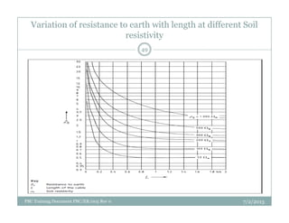
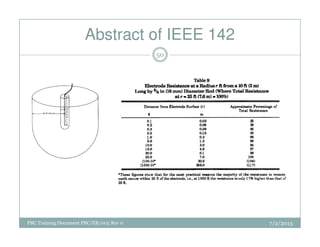
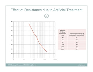
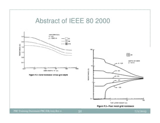
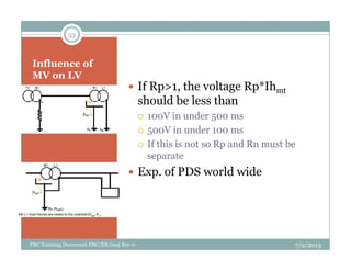
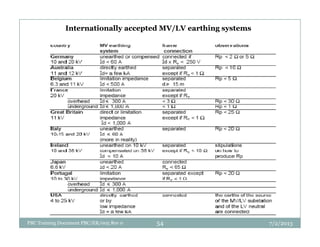
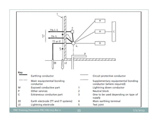
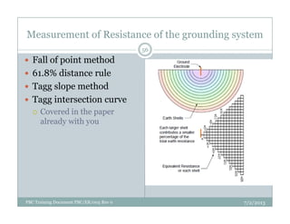
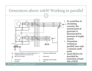
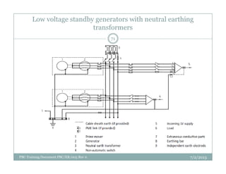
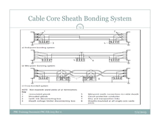
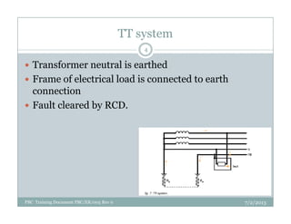
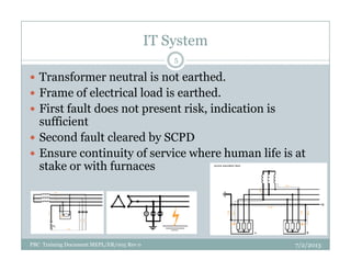
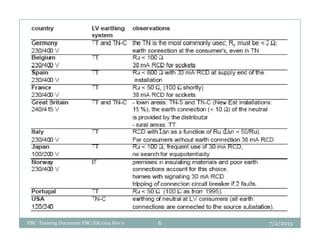
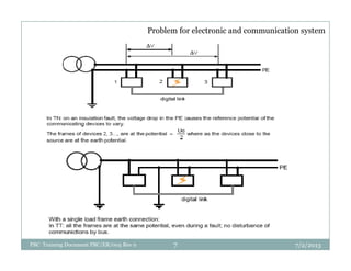
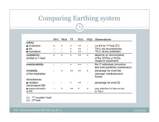
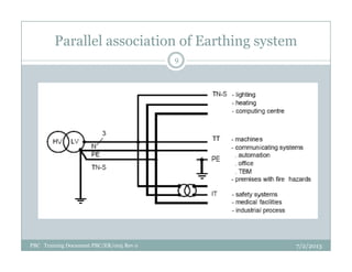
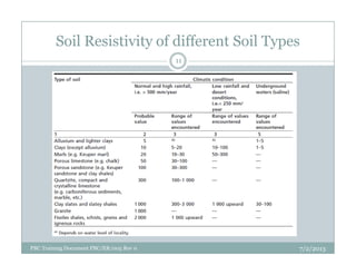
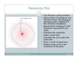
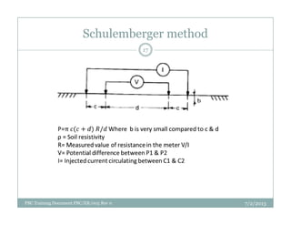
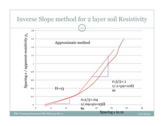
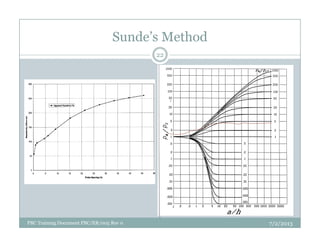
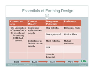
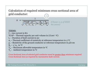
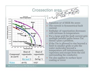
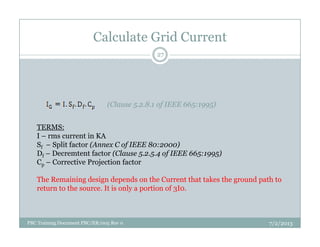
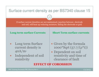
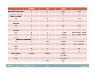
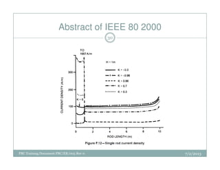
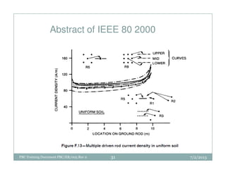
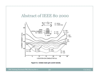
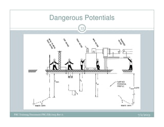
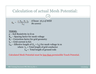
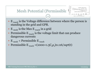
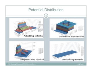
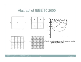
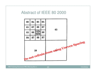
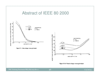
At the outset we wish to thank you for the curtsey and excellent response from you and active interest in taking a comprehensive view of modern safe Lightning Protection / Earthing and the underlying scientific principles as we posted in our Linkedin Profile, which is for your ready reference.
Electrical substation (one and half breaker scheme)Sourabh sharma
Double Bus One and Half Breaker Scheme is mostly adopted in high voltage electrical substations (220 KV or 400KV, 700 KV). Due to many advantages of this arrangement like high selectivity, reliability and less cost as compare to other bus arrangements for power stations or switch yards
This document discusses partial discharge (PD) testing methods for predictive maintenance of medium voltage switchgear. It provides definitions and explanations of partial discharge from standards bodies like IEC and IEEE. It describes the three main types of PD sources as internal, surface, and corona discharge. It then explains various online and offline PD testing methods like ultrasonic, transient earth voltage, high frequency current transformer, and the capacitance voltage divider method. Key aspects of each method like frequency ranges, sensor placement, and background noise measurement are outlined. Causes of partial discharge like cavities, electrical trees, water trees, and corona are described in detail.
The document discusses busbar protection, including the need for busbar protection, types of busbar protections like high impedance, medium impedance and low impedance protections. It describes the requirements of busbar protection like short tripping time and stable operation during external faults. The document discusses different busbar arrangements and applications of numerical busbar protection systems like RADSS. It provides examples of busbar protection schemes for different bus configurations. The document also includes excerpts from technical manuals providing recommendations on busbar protection in substations.
Random switching of power system equipment may lead to high-frequency overvoltage transient and inrush current.
This, in turn, may stress the equipment, leading to rapid aging or dielectric failure.
What is ?
Point on Wave Controller/ Switch?
Point on Wave Switch (PoW), often called Point on Wave Controller is a high speed microprocessor based relay used for the controlled switching of circuit breaker of HVAC system. Controlled switching refers to open or close a breaker at a pre-determined point on the voltage waveform.
The document discusses various aspects of partial discharge (PD) testing, including definitions, types, and detection methods. It defines PD as localized electrical discharges that only partially bridge insulation between conductors. Four main types are discussed: corona, surface, cavity, and treeing discharges. Detection methods covered include electrical, acoustic, UHF, optical, and chemical (DGA) techniques. The electrical method measures apparent charge, while acoustic localization and UHF detection have advantages of immunity to electromagnetic noise. Optical detection relies on light emission during discharges. A comparison table outlines advantages and disadvantages of each detection method.
The document discusses substations and their components. It defines a substation as an assembly of apparatus that transforms electrical energy from one form to another, such as changing voltage levels. Substations contain step-up transformers to increase voltage for transmission and step-down transformers to decrease voltage for distribution to consumers. The document describes various types of substations and explains their functions. It also provides details about components within substations such as circuit breakers, transformers, buses, isolators and instrument transformers.
Bus Bar protection Schemes,Simple Current differential scheme,Need for bus bar protection,requirement of bus bar protection,recommendations for providing bus bar protection,basics of busbar protection,Types of bus-bar protections,High speed differential protection
Earthing in a substation is important for safety. It involves connecting electrical equipment to earth at a uniform low potential to limit dangerous voltages under fault conditions. Key aspects of substation earthing design include soil resistivity testing, sizing the earth mat conductor based on fault current and duration, and ensuring step and touch potentials remain below safety limits. Proper earthing aims to provide protection to life and property against faults.
Grounding or earthing offers two principal advantages. First, it provides protection to the power system. Secondly, earthing of electrical equipment ensures the safety of the persons handling the equipment.
Principles of Cable Sizing; current carrying capacity, voltage drop, short circuit.
Cables are often the last component considered during system design even if in many situations cables are the true system’s lifeline: if a cable fails, the entire system may stop. Cable reliability is therefore extremely important, then a cable system should be engineered to last the life of the system in the installation environment for the required application. Environments in which cable systems are being used are often challenging, as extreme temperatures, chemicals, abrasion, and extensive flexing. These variables have a direct impact on the materials used for cable insulation and jacketing as well as the construction of the cable. Using a systematic approach will help ensure that designer select the best cable for the required application in the installation environment. This lessons will provide students main guidelines for perform this approach.
As the AIS (Air-Insulated Substation) is having more limitations, More and more people are going for the Gas-Insulated Substation which is environment friendly as well.
In these presentation, We discussed about theoritical and technological advancement and advantages related to GIS as compared to other substations.
We discussed different parts of the GIS as well as their operations and advantages.
By going through this presentation, you will have idea regarding comparative advantages and disadvantages of both substations.
This document provides details on substation layout and busbar arrangements. Part A discusses substation layout, including a single line diagram and descriptions of common switchyard accessories like lightning arrestors, CVTs, isolators, circuit breakers, transformers, and other equipment. It also covers PLCC and SCADA systems. Part B covers various busbar arrangements like the single bus system, double bus system, one and a half breaker system, and ring main bus system. It discusses the advantages and disadvantages of each configuration. In summary, the document is a technical report that outlines and compares different substation and busbar designs.
This document provides guidelines for properly installing an earthing system. It describes the working process which includes 1) checking materials and tools, 2) excavating for cable installation, 3) fitting earth rods and connecting them with cables using appropriate joining methods, 4) checking connections and resistance values, and 5) backfilling. Key points emphasized are using the correct accessories sizes, placing earth points at least 10 feet apart, and creating new points if resistance is more than 10% of requirements. Following the outlined process helps ensure a high quality, code-compliant earthing system installation.
This document defines and discusses various types of final circuits and their load estimations. It begins by defining a final circuit and outlet. It then discusses 7 types of final circuits: 1) circuits feeding fixed equipment or 2A sockets, 2) circuits feeding 13A sockets (BS 1363), 3) circuits feeding sockets (BS 196), 4) circuits feeding sockets (BS EN 60309-2), 5) circuits feeding fluorescent or discharge lighting, 6) circuits feeding motors, and 7) circuits feeding cookers. For each type, it provides details on load assumptions, cable sizing, and protection device ratings based on IEE guidelines. It also discusses diversity factor and defines maximum demand.
Using High Resistance Grounding to Mitigate Arc Flash Hazardsmichaeljmack
Using High Resistance Grounding to Mitigate Arc Flash Hazards
Presenter: Ajit Bapat, P.E.
I-GARD's HRG systems can detect ground faults, signal alarms, and locate affected circuits to remove personnel from arc flash dangers. I-GARD's FALCON provides fast arc flash mitigation in under 1ms through adjustable light sensitivity to reduce arc flash energy. I-GARD's arc flash analysis calculates risk using IEEE and NFPA equations to develop comprehensive protection plans for a safer work environment.
Tutorial on Distance and Over Current ProtectionSARAVANAN A
Contents
• Protection Philosophy of ERPC
• Computation of Distance Relay Setting
• System Study to Understand Distance Relay
Behaviour
• DOC and DEF for EHV system
This document provides an overview of the electrical equipment found in a switchyard at an NTPC power plant, including transformers, conductors, insulators, isolators, busbars, lightning arresters, circuit breakers, relays, and capacitor banks. It describes the purpose and basic functioning of each type of equipment, such as how transformers change voltage levels, current transformers reduce current readings, conductors transmit power, and relays and circuit breakers disconnect faulty circuits. The document also notes that new technologies like SCADA allow remote control and monitoring of substations.
The document provides information about various components and circuits in a substation including:
- Circuit breaker auxiliary switches, pressure switches, annunciation, and indication circuits.
- Circuit breaker operating mechanisms, arc quenching methods, and interlocks.
- Closing and tripping circuits for circuit breakers.
- Types of relays including bistable, monostable, anti-pumping contactor, and pole discrepancy relays.
- Inputs and outputs of relays, local/remote switches, and wiring types.
- Potential transformers, current transformers, and their distribution including nameplate details.
- AC and DC circuits and their purposes including protection, control
A surge diverter protects electrical equipment from voltage surges by diverting excess voltages caused by spikes in the electrical supply to earth. There are different types of surge diverters, including rod gap, protector tube, and valve type diverters. Rod gap diverters consist of two rods with a gap that sparks over during a surge to discharge current to ground. Protector tube diverters improve on rod gaps by enclosing the gaps to extinguish follow-on arcs. Valve type diverters incorporate non-linear resistors to provide a low resistance path for surges while blocking normal voltages and currents.
This document discusses various protection schemes and current transformer design requirements to support them. It covers overcurrent, unit, differential, and distance protection. It describes high and low impedance differential protection and the differences in their current transformer requirements. Key factors discussed are current transformer knee point voltage, ratio, burden, and saturation performance for different applications like busbar, generator, and line protection.
Grounding in Power System Presentation
The presentation discusses the importance of grounding in power systems for safety, equipment protection, and building protection from lightning strikes. It covers types of grounding including solid grounding, resistance grounding, reactance grounding, and resonant grounding. Measurement instruments and calculation procedures for proper grounding are also reviewed. Lack of proper grounding can cause electric shocks, fires, and equipment damage. IEEE standards provide guidelines for industrial and commercial grounding systems.
This PPT explains about the circuit breaker, and its types. Then about the need and purpose of the circuit breaker. And finally the testing and types of testing of circuit breakers.
CONDUCTION & BREAKDOWN IN LIQUID DIELECTRICS|HIGH VOLTAGE ENGINEERING|ELECTRI...Prasant Kumar
This document discusses conduction and breakdown in liquid dielectrics. It explains that the breakdown voltage depends on factors like the electric field, gap separation, cathode work function, liquid viscosity, temperature, and molecular structure. The presence of dissolved gases, especially electronegative gases like oxygen, can increase the breakdown strength of liquids. Commercial liquids contain impurities like gas bubbles and suspended particles that reduce their breakdown strength. Finally, many external factors influence liquid dielectric breakdown, such as electrode configuration, material, size and finish, voltage type/period/magnitude, temperature, pressure, liquid purification, and aging condition.
This presentation gives detailed information about power quality i.e. how poor power quality is caused? what are the parameters on which we measure power quality? how can we solve the problem of poor power quality? this presentation will give you all the answers.
Chap 8_Mechanical Design of Overhead Tx Line_Part 2.pptxDaniyalAhmadKhan3
A string of suspension insulators consists of multiple porcelain discs connected by metal links. The potential across each disc is not uniform due to the presence of shunt capacitance between the metal fittings and earth. The disc nearest the conductor has the highest voltage. String efficiency is defined as the ratio of average potential difference across discs to the total potential difference across the string, and indicates how uniformly potential is distributed. Higher string efficiency corresponds to more uniform distribution. Various factors like number of discs, ratios of self to shunt capacitance affect the string efficiency.
Introduction, Factors affecting system planning, present planning techniques, planning models, Sub-transmission and substation design. Sub-transmission networks configurations, Substation bus schemes, Distribution substations ratings, Service areas calculations, and Substation application curves, future trends in planning, systems approach, and Distribution automation.
This document describes the features and measurement techniques of an instrument used to measure earth electrode resistance and soil resistivity. It can measure resistance from 0.01 to 200 KΩ. The instrument is IP54 rated and allows for 2, 3, and 4-point testing using attached rods or stakeless measurement. It has user-selectable test frequencies and output voltages. The document explains the principles and procedures for two-terminal, three-terminal, attached rod, stakeless, and four-terminal resistance and resistivity measurements. Potential and current probe resistances and ground noise voltages are also discussed.
This document provides an overview and discussion of automatic transfer switches, grounding issues, and installation considerations for standby power systems. It discusses NFPA 110 requirements, grounding terminology and rules, applications of 4-pole switches, fuel system considerations and sizing, generator control functions, transfer switch types, and indoor versus outdoor generator installation options. The key topics covered are the two main grounding rules, uses of 4-pole automatic transfer switches, fuel system design best practices, and NFPA 110 compliance guidelines for emergency power systems.
The document presents information on earthing systems. It discusses the functions of earthing, which include providing a path for fault currents and protection from electric shock. It describes various methods of earthing, including plate earthing, pipe earthing, and rod earthing. It also discusses different types of earthing systems and applications of earthing in electrical systems. In conclusion, it emphasizes the importance of proper grounding and earthing in electrical engineering for safety and protection of electrical equipment.
Each month, join us as we highlight and discuss hot topics ranging from the future of higher education to wearable technology, best productivity hacks and secrets to hiring top talent. Upload your SlideShares, and share your expertise with the world!
Not sure what to share on SlideShare?
SlideShares that inform, inspire and educate attract the most views. Beyond that, ideas for what you can upload are limitless. We’ve selected a few popular examples to get your creative juices flowing.
SlideShare is a global platform for sharing presentations, infographics, videos and documents. It has over 18 million pieces of professional content uploaded by experts like Eric Schmidt and Guy Kawasaki. The document provides tips for setting up an account on SlideShare, uploading content, optimizing it for searchability, and sharing it on social media to build an audience and reputation as a subject matter expert.
Modeling and Analysis of a 3-Phase 132kv GasInsulated SubstationIRJET Journal
1) The document discusses modeling and analysis of very fast transient overvoltages in a 3-phase 132kV gas insulated substation using MATLAB 7.8 software.
2) Equivalent circuits for different components of the substation were developed in MATLAB to simulate transient overvoltages caused by switching operations and faults.
3) Transient overvoltages were analyzed for different lengths of the gas insulated bus duct and various voltages on the source and load sides to determine maximum overvoltage levels.
This document analyzes grounding considerations for large kVA pad-mount transformers. It summarizes the assumptions made in analyzing different transformer voltages and kVA sizes up to 5,000 kVA. Calculations of ground potential rise, touch potential and step potential are performed and compared to safety limits. Results show the standard two ground rod system may not provide adequate protection for transformers over 750 kVA or higher secondary voltages. Larger or engineered grounding systems are recommended for safety.
The document discusses grounding considerations for large kVA pad-mount transformers. It analyzes grounding systems for pad-mounts up to 5,000 kVA to ensure step and touch potentials are limited to safe levels. Calculations were performed using IEEE standards to determine the maximum allowable touch and step voltages. Results showed the standard two ground rod system may not limit surface potentials for all sizes, while the Canadian four rod standard provided better but still insufficient results for some larger transformers. Recommendations are made to properly design grounding to render pad-mounts safe for the public and workers.
This document summarizes ASTM Standard Test Method G 57-95 for measuring soil resistivity using the Wenner four-electrode method. It describes the equipment, procedures, and calculations for taking resistivity measurements both in situ in the field and on soil samples. Key steps include selecting electrode spacings based on the structure of interest, impressing a voltage between outer electrodes to induce current flow, and measuring the voltage drop between inner electrodes to calculate resistivity. Interpretation of resistivity surveys involves considering mean/median values and changes in resistivity to assess general and local soil corrosivity.
The document summarizes the design and analysis of grounding grids for substations using various methods. It presents 4 case studies analyzing an existing 500kV substation grounding grid using IEEE 80-2000 and finite element methods in ETAP software. The case studies vary parameters like number of conductors, rods, and grid area to optimize the design to meet safety limits for touch and step voltages. While some cases improve issues like temperature rise, all cases show touch voltages exceeding limits, requiring further optimization of the grounding grid design.
Sphere gaps can be used to measure high voltages up to 2500 kV. They work by measuring the sparkover voltage between two conductive spheres. The standard diameters for the spheres are between 6.25 cm to 200 cm. Various factors like humidity, temperature, and pressure can influence the sparkover voltage. Sphere gaps are accurate to within 3% for measurements if the spacing between the spheres is less than half the sphere diameter.
The document provides details on a schedule of topics to be covered in an electrical distribution course from October 2005 to December 2005. It then provides information on sizing conduits and trunking for electrical installations, including the types of available conduits and trunking, factors to consider when sizing them, and examples of conduit and trunking sizing calculations. Relevant standards for conduits, trunking, and cable selection are also referenced.
A Novel Design of a Microstrip Microwave Power Amplifier for DCS Application ...IJECEIAES
This paper presents a 1.80GHz class-A Microwave power amplifier (PA). The proposed power amplifier is designed with single-stage architecture. This power amplifier consists of a bipolar transistor and improved by Collector-Feedback Biasing fed with a single power supply. The aim of this work is to improve the performance of this amplifier by using simple stubs with 50Ω microstrip transmissions lines. The proposed PA is investigated and optimized by utilizing Advanced Design System (ADS) software. The simulation results show that the amplifier achieves a high power gain of 13dB, output power rise up to 21dBm and good impedances matching ;For the input reflection coefficient (S11) is below than - 46.39dB. Regarding the output reflection coefficient (S22) is below than -29.898dB, with an overall size of about 93 x 59mm². By the end; we find that this power amplifier offers an excellent performance for DCS applications.
This document discusses the analysis of grounding systems for substations. It analyzes the grounding system design for a 220/132/33 kV substation in India as a case study. The key factors considered in grounding system design are discussed, including fault current magnitude, transient overvoltage protection, and safety. Calculations are shown for sizing conductors, determining grid resistance and step/touch voltages based on soil resistivity and other input parameters. The results found that the designed grounding system met safety requirements, with attainable step and touch voltages below tolerable limits and a grid resistance under 1 ohm. Proper grounding system analysis and design is important for safety during faults.
Improvement of Transient Stability in Doubly Fed Induction Wind Generator usi...IRJET Journal
This document discusses improving transient stability in doubly fed induction wind generators using a bridge-type fault current limiter (BFCL). It first provides background on doubly fed induction generators and introduces the BFCL. It then describes modeling the generator, controllers, BFCL, and compares the BFCL to a series dynamic braking resistor for limiting fault current. Simulation results are presented and show the BFCL more effectively improves transient stability during symmetrical and asymmetrical faults compared to the resistor. The conclusion is that the BFCL is very efficient at improving transient stability in doubly fed induction generator-based wind farms to meet grid code requirements, and performs better than the resistor except for cost.
Life Cycle of Big Data Analysis by using MapReduce AlgorithmIRJET Journal
This document discusses improving transient stability in doubly fed induction wind generators using a bridge-type fault current limiter (BFCL). It first provides background on doubly fed induction generators and introduces the BFCL. It then describes modeling the wind turbine, doubly fed induction generator, rotor and grid side controllers. Operation and control of the BFCL is explained and compared to a series dynamic braking resistor (SDBR) approach. Simulation results show the BFCL more effectively improves transient stability during faults compared to the SDBR. The document concludes the BFCL is very efficient at improving transient stability in doubly fed induction generator-based variable speed wind turbines to meet grid code requirements, and is more effective than SDBR except for potential
This paper proposes fault location model for underground power cable using microcontroller. The aim of this project is to determine the di stance of underground cable fault from base station in kilometers. This project uses the simple c oncept of ohm�s law.When any fault like short circuit occurs,voltage drop will vary depending on the length of fault in cable,since the current varies. A set of resistors are ther efore used to represen t the cable and a dc vol tage is fed at one end and the fault is detected by detecting the change in voltage using a analog to voltage converter and a microcontroller is used to make the necessary calculations so that the fault distance is displayed on the LCD display.
Tertiary interbus transformer and alternative protectionSouvik Dutta
This document summarizes a literature study on the condition of tertiary bushings in interbus transformers and alternative protection schemes. It discusses how directly earthing the delta-connected tertiary winding raises the voltage stress on bushings, potentially reducing their lifetime. Online monitoring data is presented showing abnormalities in bushing parameters like tan δ. Literature suggests continuously operating bushings at 1.571 times rated voltage could reduce lifetime to around 2.5 years. The document evaluates direct earthing and floating schemes for protecting the tertiary winding.
Design of bridgeless high-power-factor buck-converter operating in discontinu...IRJET Journal
The document proposes a new bridgeless buck converter operating in discontinuous capacitor voltage mode (DCVM) for power factor correction. Key advantages of the proposed topology include lower conduction losses compared to conventional topologies due to fewer simultaneously conducting semiconductor components. The DCVM operation provides zero-voltage switching for the power switches and zero-voltage turn-on for the output diode, improving efficiency. Simulation results show the converter achieves high power factor and low total harmonic distortion in the input current under different load conditions.
The document describes a project report on three phase fault analysis with auto reset. It includes a block diagram of the project, descriptions of the hardware components used including transformers, voltage regulators, 555 timers, and relays. It also includes schematic and layout diagrams and details on testing the hardware. The system is designed to automatically disconnect the three phase power supply in the event of a fault, with the supply automatically resetting for temporary faults but remaining tripped for permanent faults.
PROJECT DESCRIPTION
DOWNLOAD
The main objective of this project is to develop a device for wireless power transfer. The concept of wireless power transfer was realized by Nikolas tesla. Wireless power transfer can make a remarkable change in the field of the electrical engineering which eliminates the use conventional copper cables and current carrying wires.
Based on this concept, the project is developed to transfer power within a small range. This project can be used for charging batteries those are physically not possible to be connected electrically such as pace makers (An electronic device that works in place of a defective heart valve) implanted in the body that runs on a battery.
The patient is required to be operated every year to replace the battery. This project is designed to charge a rechargeable battery wirelessly for the purpose. Since charging of the battery is not possible to be demonstrated, we are providing a DC fan that runs through wireless power.
This project is built upon using an electronic circuit which converts AC 230V 50Hz to AC 12V, High frequency. The output is fed to a tuned coil forming as primary of an air core transformer. The secondary coil develops a voltage of HF 12volt.
Thus the transfer of power is done by the primary(transmitter) to the secondary that is separated with a considerable distance(say 3cm). Therefore the transfer could be seen as the primary transmits and the secondary receives the power to run load.
Moreover this technique can be used in number of applications, like to charge a mobile phone, iPod, laptop battery, propeller clock wirelessly. And also this kind of charging provides a far lower risk of electrical shock as it would be galvanically isolated.
Underground Cable Fault Detection Using ArduinoIRJET Journal
This document describes a project to detect faults in underground cables using an Arduino. It contains the following key points:
1. The project uses a circuit of resistors connected to an Arduino to represent the length of an underground cable. Switches placed at 1 km intervals can induce faults manually.
2. When a fault occurs, the Arduino and its ADC convert the analog current readings to digital data to determine the precise location of the fault in kilometers.
3. The document reviews related work on cable fault detection and discusses cable types, common fault types like earth faults and short circuits, and methods like Time Domain Reflectometry that have been used.
This document describes using active disturbance rejection control (ADRC) for controlling a single-stage photovoltaic system connected to the electrical grid. It compares ADRC to the conventional perturb and observe (P&O) control method. ADRC combined with incremental conductance (ADRC-IC) is used for maximum power point tracking (MPPT) control. ADRC is also used to control the inverter to regulate the DC bus voltage and ensure unity power factor injection into the grid. The system aims to maximize power extraction from the PV array and regulate power injection into the grid with low harmonics.
The document describes a project report on wireless power transfer submitted by a student for their Bachelor of Technology degree. It includes a cover page, certificate from the project guide, acknowledgements, declaration, table of contents, and sections describing the abstract, block diagram, hardware requirements including various electronic components, schematic diagram, hardware testing, results, future prospects, medical applications, and conclusion.
Similar to Technical presentation on modern earthing (20)
Introduction- e - waste – definition - sources of e-waste– hazardous substances in e-waste - effects of e-waste on environment and human health- need for e-waste management– e-waste handling rules - waste minimization techniques for managing e-waste – recycling of e-waste - disposal treatment methods of e- waste – mechanism of extraction of precious metal from leaching solution-global Scenario of E-waste – E-waste in India- case studies.
Rainfall intensity duration frequency curve statistical analysis and modeling...bijceesjournal
Using data from 41 years in Patna’ India’ the study’s goal is to analyze the trends of how often it rains on a weekly, seasonal, and annual basis (1981−2020). First, utilizing the intensity-duration-frequency (IDF) curve and the relationship by statistically analyzing rainfall’ the historical rainfall data set for Patna’ India’ during a 41 year period (1981−2020), was evaluated for its quality. Changes in the hydrologic cycle as a result of increased greenhouse gas emissions are expected to induce variations in the intensity, length, and frequency of precipitation events. One strategy to lessen vulnerability is to quantify probable changes and adapt to them. Techniques such as log-normal, normal, and Gumbel are used (EV-I). Distributions were created with durations of 1, 2, 3, 6, and 24 h and return times of 2, 5, 10, 25, and 100 years. There were also mathematical correlations discovered between rainfall and recurrence interval.
Findings: Based on findings, the Gumbel approach produced the highest intensity values, whereas the other approaches produced values that were close to each other. The data indicates that 461.9 mm of rain fell during the monsoon season’s 301st week. However, it was found that the 29th week had the greatest average rainfall, 92.6 mm. With 952.6 mm on average, the monsoon season saw the highest rainfall. Calculations revealed that the yearly rainfall averaged 1171.1 mm. Using Weibull’s method, the study was subsequently expanded to examine rainfall distribution at different recurrence intervals of 2, 5, 10, and 25 years. Rainfall and recurrence interval mathematical correlations were also developed. Further regression analysis revealed that short wave irrigation, wind direction, wind speed, pressure, relative humidity, and temperature all had a substantial influence on rainfall.
Originality and value: The results of the rainfall IDF curves can provide useful information to policymakers in making appropriate decisions in managing and minimizing floods in the study area.
Comparative analysis between traditional aquaponics and reconstructed aquapon...bijceesjournal
The aquaponic system of planting is a method that does not require soil usage. It is a method that only needs water, fish, lava rocks (a substitute for soil), and plants. Aquaponic systems are sustainable and environmentally friendly. Its use not only helps to plant in small spaces but also helps reduce artificial chemical use and minimizes excess water use, as aquaponics consumes 90% less water than soil-based gardening. The study applied a descriptive and experimental design to assess and compare conventional and reconstructed aquaponic methods for reproducing tomatoes. The researchers created an observation checklist to determine the significant factors of the study. The study aims to determine the significant difference between traditional aquaponics and reconstructed aquaponics systems propagating tomatoes in terms of height, weight, girth, and number of fruits. The reconstructed aquaponics system’s higher growth yield results in a much more nourished crop than the traditional aquaponics system. It is superior in its number of fruits, height, weight, and girth measurement. Moreover, the reconstructed aquaponics system is proven to eliminate all the hindrances present in the traditional aquaponics system, which are overcrowding of fish, algae growth, pest problems, contaminated water, and dead fish.
Redefining brain tumor segmentation: a cutting-edge convolutional neural netw...IJECEIAES
Medical image analysis has witnessed significant advancements with deep learning techniques. In the domain of brain tumor segmentation, the ability to
precisely delineate tumor boundaries from magnetic resonance imaging (MRI)
scans holds profound implications for diagnosis. This study presents an ensemble convolutional neural network (CNN) with transfer learning, integrating
the state-of-the-art Deeplabv3+ architecture with the ResNet18 backbone. The
model is rigorously trained and evaluated, exhibiting remarkable performance
metrics, including an impressive global accuracy of 99.286%, a high-class accuracy of 82.191%, a mean intersection over union (IoU) of 79.900%, a weighted
IoU of 98.620%, and a Boundary F1 (BF) score of 83.303%. Notably, a detailed comparative analysis with existing methods showcases the superiority of
our proposed model. These findings underscore the model’s competence in precise brain tumor localization, underscoring its potential to revolutionize medical
image analysis and enhance healthcare outcomes. This research paves the way
for future exploration and optimization of advanced CNN models in medical
imaging, emphasizing addressing false positives and resource efficiency.
1. O N M O D E R N C O N C E P T S A N D A D V A N C E D
T E C H N I Q U E S O F E A R T H I N G
1
Technical Presentation to
PROJECT PRICIPALS
B Y P A N K A J C H A K R A B O R T Y
OF
PBC INDUSTRIAL SERVICES
B L O C K – 1 9 , F L A Y – 1 1 7 ,
P A R N A S R E E G O V T . H O U S I N G ,
K O L K A T A – 7 0 0 0 6 0 , ( W E S T - B E N G A L )
7/2/2013PBC Training Document PBC/ER/005 Rev 0
2. Objectives
Return path during continuous operation should not
be thru earth path unless designed.
Instantaneous fault current should not flow thru the
neutral circuit creating live and dangerous neutral.
Dissipate the stray currents, lightning, surges
2
Dissipate the stray currents, lightning, surges
keeping system hazard free.
Maintain the whole facility at equipotential.
Provide reference to run the system at specified
voltage
7/2/2013PBC Training Document PBC/ER/005 Rev 0
3. TN System
Transformer neutral is earthed
Frames of electrical load are connected to neutral
Fault is cleared by SCPD
3
Fault is cleared by SCPD
TN-C, TN-S, TN-CS
SCPD/ loop impedance matching
Not recommended for premises having electronic and
communication system
Not used when cross-section of live cond. < 10 sqmm
PE may get damaged by loads generating 3rd harmonics.
7/2/2013PBC Training Document PBC/ER/005 Rev 0
4. TT system
Transformer neutral is earthed
Frame of electrical load is connected to earth
connection
Fault cleared by RCD.
4
7/2/2013PBC Training Document PBC/ER/005 Rev 0
5. IT System
Transformer neutral is not earthed.
Frame of electrical load is earthed.
First fault does not present risk, indication is
sufficient
Second fault cleared by SCPD
5
Second fault cleared by SCPD
Ensure continuity of service where human life is at
stake or with furnaces
7/2/2013PBC Training Document MEPL/ER/005 Rev 0
10. BREAK 1
10
T H I N K I N G T I M E
PBC Training Document PBC/ER/005 Rev 0 7/2/2013
11. Soil Resistivity of different Soil Types
11
7/2/2013PBC Training Document PBC/ER/005 Rev 0
12. Resistivity Plot
Use Wenner 4 point method.
Take at least 4 readings in one
direction from 7mt spacing to
spacing equal to diagonal of
the electrical installation.
Repeat these readings in all 8
directions separated by 450
angle.
12
7/2/2013PBC Training Document PBC/ER/005 Rev 0
angle.
Calculate the resistivity.
Make a polar plot.
Calculate the area under the
polar plot
Draw a circle of equal area
Radius of the circle is the
resistivity of the point.
18. Essential Practices
Use meter
having stray current filter.
where the injected current frequencies can be changed
Injected current can be made high or low depending on current
probe resistance.
Apply water and compact the current and potential
18
Apply water and compact the current and potential
probes to avoid undue high probe resistance.
Lose potential probe can give high value of R and high
resistivity.
Avoid measuring along buried or superficial metal
conductors
Take readings in multiple directions
7/2/2013
19. Abstract of IEEE 81 1993
19
PBC Training Document PBC/ER/005 Rev 0 7/2/2013
20. Polar curve method for Uniform Soil
Resistivity
• Resistivity taken in min 8
directions
• Angular distance between
readings 450
• Cautiously Interpolate the
readings to 7.50
• Join the Points to form a polar
curve
20
PBC Training Document PBC/ER/005 Rev 0
curve
• Calculate the area of the polar
curve
• Draw equivalent Circular area
• Radius of the circle is the average
soil resistivity
• This method is particularly
beneficial when the resistivity
varies significantly in different
directions
7/2/2013
21. Inverse Slope method for 2 layer soil Resistivity
1
1.2
1.4
1.6
1.8
Spacings/apparentresistivityρa
Approximate method
21
PBC Training Document PBC/ER/005 Rev 0
0
0.2
0.4
0.6
0.8
1
0 5 10 15 20 25 30 35
0.5/5=.1
1/.1=ρ2=10Ω
m
Spacings/apparentresistivity
Spacing s in m
0.2/5=.04
1/.04=ρ1=25Ω
m
H=13
7/2/2013
23. BREAK 2
23
T H I N K I N G T I M E
PBC Training Document PBC/ER/005 Rev 0 7/2/2013
24. Essentials of Earthing Design
Crossection
Area
Current
Density
Dangerous
Potentials
Resistance
The Crossection
of the conductor
to be sufficient
for carrying
Continuous
surface current
density
Step potential Horizontal Plane
Touch potential Vertical Plane
24
PBC Training Document PBC/ER/005 Rev 0
for carrying
GRID fault
current Instantaneous
Surface current
density
Mesh Potential Mutual
resistance
GPR
Transfer
Potential
PASS PASS PASSPASS OK
7/2/2013
25. (Clause 11.3 of IEEE
80:2000)
TERMS:
I – rms current in KA
TCAP – Thermal capacity per unit volume in J/(cm3. 0C)
Calculation of required minimum cross sectional area of
grid conductor:
25
TCAP – Thermal capacity per unit volume in J/(cm . C)
tc – Duration of fault current in sec
αr – Thermal coefficient of resistivity at reference temperature in 1/0C
ρr – Resistivity of the ground conductor at reference temperature in µ -cm
Ko – 1/ α0 in 0C
Tm – Maximum allowable temperature in 0C
Ta – Ambient temperature in 0C
Cross Sectional Area of selected grid conductor must be greater than minimum required
Cross Sectional Area as required by Asymmetric fault current.
7/2/2013PBC Training Document PBC/ER/005 Rev 0
26. Crossection area
Equation 37 of IEEE 80 2000
The current is Symmetrical fault
current
Enthalpy of vaporization decreases
with increase in temperature.
For a large grid the fault current gets
See also
26
PBC Training Document PBC/ER/005 Rev 0
For a large grid the fault current gets
multiple parallel paths hence Tm
doesn’t pose a problem.
If the Tm is allowed to rise beyond a
limit in smaller grids or pits the
water molecules beyond a
temperature will instantaneously
vaporizes and escape from the soil
surrounding the conductor.
Tm also applies to surface layer
coating or cover
Compound
At 1000C
Heat of
vaporizatio
n
(kJ mol-1)
Heat of
vaporizatio
n
(kJ kg−1)
Water 40.65 2257
7/2/2013
27. Calculate Grid Current
(Clause 5.2.8.1 of IEEE 665:1995)
TERMS:
27
TERMS:
I – rms current in KA
Sf – Split factor (Annex C of IEEE 80:2000)
Df – Decremtent factor (Clause 5.2.5.4 of IEEE 665:1995)
Cp – Corrective Projection factor
The Remaining design depends on the Current that takes the ground path to
return to the source. It is only a portion of 3I0.
7/2/2013PBC Training Document PBC/ER/005 Rev 0
28. Long term surface CurrentsLong term surface Currents Short Term surface currentsShort Term surface currents
Surface current density as per BS7340 clause 15
If surface current densities are not maintained, junction between electrode
and soil, will heat up reducing moisture, failing the electrode or grid.
28
PBC Training Document PBC/ER/005 Rev 0
Long term Surface
current density is
40A/m2
Independent of soil
resistivity
Given by the formula
1000*Sqrt (57.7/(ρ*t))
Dependent on soil
resistivity and time of
clearance of fault
EFFECT OF COROSSION
7/2/2013
29. Symbol unit Value
Relay setting at 6KA 0.32Sec IG A 6000 Input
Diameter of electrode d m 0.04 Input
Length of Electrode
Soil ls m 37 Input
Water lw m 1 Input
Resistivity
Soil ρs Ωm 360 Input
Water ρw Ωm 2 Input
Resistance
Soil Rs Ω 12.25394 Equation 55 IEEE 80 2000
Water Rw Ω 1.368891 Equation 55 IEEE 80 2000
Combined R Ω 1.231338
7/2/2013PBC Training Document PBC/ER/005 Rev 0
Combined Rc Ω 1.231338
Permissible Current Density
Soil σs A/m2 730.9304 Clause 15.2 BS7340
Water σw A/m2 9806.46 Clause 15.2 BS7341
Area
Soil As m2 4.6472 πdls
Water Aw m2 0.1256 πdlw
Current Division Resistance Capacity Design
Soil 3396.779785
Water 1231.691433
TOTAL 4627 A
29
30. Abstract of IEEE 80 2000
30
PBC Training Document PBC/ER/005 Rev 0 7/2/2013
31. Abstract of IEEE 80 2000
PBC Training Document PBC/ER/005 Rev 0 7/2/201331
32. Abstract of IEEE 80 2000
PBC Training Document PBC/ER/005 Rev 0 7/2/201332
34. Voltage Variation with proximity
V
• The charges are distributed to
the surrounding soil.
• The Voltage is thus high near theV
V
• The Voltage is thus high near the
pit and low away from it
7/2/2013PBC Training Document PBC/ER/005 Rev 0 34
35. Step Potential
Calculation of permissible Step Potential:
(Clause 7.4 and 12.5 of IEEE 80:2000)
(Clause 8.3 of IEEE
35
TERMS:
ρ – Soil Resistivity in -m
ρs – Soil Resistivity of additional surface layer in -m
hs – Thickness of additional surface layer in m
ts – Shock current duration in sec
Cs – Surface layer de-rating factor
(Clause 8.3 of IEEE
80:2000)
(Clause 8.3 of IEEE
80:2000)
7/2/2013PBC Training Document PBC/ER/005 Rev 0
36. Calculation of actual Step Potential:
(Clause 16.5 of IEEE
80:2000)
TERMS:
ρ – Soil Resistivity in -m
36
ρ – Soil Resistivity in -m
Ks – Spacing factor for step voltage
Ki – Correction factor for grid geometry
IG – Grid current in KA
Ls – Effective length of (Lc + LR) for step voltage in m
where Lc = Total length of grid conductor
LR = Total length of ground rods
Calculated Step Potential must be less than permissible Step Potential.
7/2/2013PBC Training Document PBC/ER/005 Rev 0
37. Touch Potential
Calculation of permissible Touch Potential:
(Clause 7.4 and 12.5 of IEEE 80:2000)
(Clause 8.3 of IEEE
37
TERMS:
ρ – Soil Resistivity in -m
ρs – Soil Resistivity of additional surface layer in -m
hs – Thickness of additional surface layer in m
ts – Shock current duration in sec
Cs – Surface layer de-rating factor
(Clause 8.3 of IEEE
80:2000)
(Clause 8.3 of IEEE
80:2000)
7/2/2013PBC Training Document PBC/ER/005 Rev 0
38. Calculation of actual Mesh Potential:
(Clause 16.5 of IEEE
80:2000)
TERMS:
ρ – Soil Resistivity in -m
Km – Spacing factor for mesh voltage
38
Km – Spacing factor for mesh voltage
Ki – Correction factor for grid geometry
IG – Grid current in KA
LM – Effective length of (Lc + LR) for mesh voltage in m
where Lc = Total length of grid conductor
LR = Total length of ground rods
Calculated Mesh Potential must be less than permissible Touch Potential.
7/2/2013PBC Training Document PBC/ER/005 Rev 0
39. Tolerable currents by Humans
Frequency based (lethal values)
DC 25Hz 50/60Hz 3-10 KHz
0.5A 0.15A 0.1A high current
39
7/2/2013PBC Training Document PBC/ER/005 Rev 0
Threshold current,
tingling feeling
Let – go current.
Can release
Cannot release
energized object
Ventricular fibrillation
1 mA 1-6 mA 9-25 mA 60 - higher
0.5A 0.15A 0.1A high current
Amplitude based
40. Tolerable currents by Humans (Con.)
Weight Based Time based
40
7/2/2013PBC Training Document PBC/ER/005 Rev 0
41. Step potential (Permissible Value)
It is the concentration of charge that creates Tension or Voltage
Voltage drives the Current
Permissible Estep = (1000+6Csρs)0.116/sqrt(t)
Actual E < Permissible E
VV
Actual Estep < Permissible Estep
7/2/2013PBC Training Document PBC/ER/005 Rev 0 41
42. Mesh Potential (Permissible Value)
E touch is the Voltage difference between where the person is
standing in the grid and GPR.
E mesh is the Max E touch in a grid
Permissible E touch is the voltage limit that can produce
dangerous currents
42
dangerous currents
E mesh < Permissible E touch
Permissible E touch =(1000+1.5Csρs)0.116/sqrt(t)
7/2/2013PBC Training Document PBC/ER/005 Rev 0
43. Potential Distribution
Permissible Step PotentialActual Step Potential
43
PBC Training Document PBC/ER/005 Rev 0
Permissible Step Potential
Dangerous Step Potential
Actual Step Potential
Corrected Step Potential
7/2/2013
44. Abstract of IEEE 80 2000
PBC Training Document PBC/ER/005 Rev 0 7/2/201344
45. Abstract of IEEE 80 2000
PBC Training Document PBC/ER/005 Rev 0 7/2/201345
46. Abstract of IEEE 80 2000
PBC Training Document PBC/ER/005 Rev 0 7/2/201346
47. Ring Earth
•The concentric conductors reduce the resistance
significantly
•The reactance is reduced by tying the rings to
each other at the corners
•A ramp arrangement is followed burying the out
conductors deeper than the inner conductors to
47
7/2/2013PBC Training Document PBC/ER/005 Rev 0
conductors deeper than the inner conductors to
obtain a gradual potential curve
48. Formulae to Calculate Resistance
for plate earthing
R = (ρ/4)* sqrt (π/2A)
for pipe earthing
R = (ρ/2πL)* [ln (8L/d)-1]
for strip earthing
R=(ρ/PπL)* [ln (2L2 /(wh))+ Q]
48
PBC Training Document PBC/ER/005 Rev 0
R=(ρ/PπL)* [ln (2L2 /(wh))+ Q]
for grid earthing
R=ρ[(1/LT)+ (1/sqrt (20A) (1+ (1/1+h) sqrt (20A)
Is Material of the grid important for achieving resistance?
No. If corrosion factor is taken care of
7/2/2013
49. Variation of resistance to earth with length at different Soil
resistivity
49
7/2/2013PBC Training Document PBC/ER/005 Rev 0
50. Abstract of IEEE 142
50
7/2/2013PBC Training Document PBC/ER/005 Rev 0
51. Effect of Resistance due to Artificial Treatment
50
60
70
80
Radius of
Artificial
treatment in
mm
Remaining percentage of
resistance to remote earth
51
PBC Training Document PBC/ER/005 Rev 0
0
10
20
30
40
1 10 100 1000 10000
Series1
30 75
60 62
90 54
150 48
300 32
1500 14
7/2/2013
52. Abstract of IEEE 80 2000
PBC Training Document PBC/ER/005 Rev 0 7/2/201352
53. Influence of
MV on LV
If Rp>1, the voltage Rp*Ihmt
should be less than
100V in under 500 ms
500V in under 100 ms
53
If this is not so Rp and Rn must be
separate
Exp. of PDS world wide
7/2/2013PBC Training Document PBC/ER/005 Rev 0
56. Measurement of Resistance of the grounding system
Fall of point method
61.8% distance rule
Tagg slope method
Tagg intersection curve
Covered in the paper
56
PBC Training Document PBC/ER/005 Rev 0
Covered in the paper
already with you
7/2/2013
57. Positioning of the potential probe
57
PBC Training Document PBC/ER/005 Rev 0 7/2/2013
58. Essential Practices
Must use insulation gear
Must keep a gap of at least 6 meters between potential and
current lead
Must insulate any joint appearing in the lead
Use meter
having stray current filter.
58
PBC Training Document PBC/ER/005 Rev 0
having stray current filter.
where the injected current frequencies can be changed
Injected current can be made high or low depending on current probe
resistance.
Apply water and compact the current and potential probes to
avoid undue high probe resistance.
Lose potential probe can give high value of R .
Avoid measuring along buried or superficial metal conductors
7/2/2013
59. Fall of point method
59
PBC Training Document PBC/ER/005 Rev 0
The average of the flat part of the graph gives the give the ground impedance
7/2/2013
60. 61.8% Distance Rule
The reading levels of at P2 61.8% of the current
probe C2
At distances lower than 61.8%, the impedance
reading is lower and dips on approaching the
resistance zone of the grid
60
PBC Training Document PBC/ER/005 Rev 0
resistance zone of the grid
Similarly the impedance reading increases as the P2
enters the resistance zone of C2
7/2/2013
62. BREAK 3
62
T H I N K I N G T I M E
PBC Training Document PBC/ER/005 Rev 0 7/2/2013
63. Earth fault Protection
Earth Fault protection in installations
Selection of device for automatic disconnection
Earth fault protection Devices
Duration 15 min
63
Duration 15 min
7/2/2013PBC Training Document PBC/ER/005 Rev 0
64. Earth Fault Protection in Installation
Trip 65V in 10 Sec, and 230 V instantaneously
Earth fault protection involves automatic disconnection
to prevent dangerous duration and magnitude of touch
voltage.
The earth fault loop impedance has to be low enough to
trip overcurrent protective devices.
64
trip overcurrent protective devices.
Where low earth fault loop impedance cannot be
achieved, disconnection may be facilitated by RCCB or
Voltage operated ELCB
RCD having minimum operating current greater than
30mA indirect shock risk protection
RCD having minimum operating current less than 30mA
direct shock risk protection
7/2/2013PBC Training Document PBC/ER/005 Rev 0
65. Voltage Operated ELCBVoltage Operated ELCB
RCD Current Operated
ELCB
RCD Current Operated
ELCB
Earth Fault Detection
65
Not suitable for protection of human
Trip coil set to operate at 50 V
7/2/2013PBC Training Document PBC/ER/005 Rev 0
68. Earthing of Captive Power Plant
Low voltage generators
High voltage generators
Duration 30 min
68
7/2/2013PBC Training Document PBC/ER/005 Rev 0
69. • It should be connected to installation main earth
• The main earth terminal should be connected to earth electrode
• Installation should be protected by RCD
• RCD cannot protect generator side of the circuit.
• For mobile loads the RCD should be 30mA with tripping time of 40mS
7/2/2013PBC Training Document PBC/ER/005 Rev 0 69
70. Generators above 10kW Working in parallel
• To avoid flow of
circulating
currents, the
neutral point of
generator is
disconnected in
presence of supply
70
7/2/2013PBC Training Document PBC/ER/005 Rev 0
presence of supply
neutral
• Generators
working in
parallel, have only
1 common earth
point.
• 30mA RCD to be
provided for
protection of load
side of RCD
RCD
71. Low voltage standby generators with neutral earthing
transformers
71
7/2/2013PBC Training Document PBC/ER/005 Rev 0
72. Cable Core Sheath Bonding System
72
7/2/2013PBC Training Document PBC/ER/005 Rev 0
73. Statutory Provisions for Earthing
Should follow Indian Electricity Rule 1956
All MV and HV equipments to be earthed by 2
separate earths
Earth electrode should be devised such that testing is
possible.
73
possible.
The value of earth resistance should be based on
degree of shock protection.
No additional source to be added with out verifying
the capacity of earthing system
7/2/2013PBC Training Document PBC/ER/005 Rev 0
74. Bibliography
IEEE 80 2000 for substation
IEEE 665 1995 for Generating Station
IEEE 142 1991 for Industrial establishment
IEEE 81 1993 for Earthing Measurements
IEEE 1100 for powering and grounding electronic equipments.
IEEE 575 for sheath bonding and induced voltagesIEEE 575 for sheath bonding and induced voltages
BS 7430 1998 Code of practice for Earthing
IS 3043-1987 Code of practice for Earthing
IEC 62305 Part 1 to Part 4
NFPA 70 and NFPA 780
API RP 2003 for statics and lightning protection
And many more ref. texts
7/2/2013PBC Training Document PBC/ER/005 Rev 0 74
75. S A F E T Y T H R U D E S I G N
Saving life and Assets
75
T H A N K Y O U
7/2/2013PBC Training Document PBC/ER/005 Rev 0