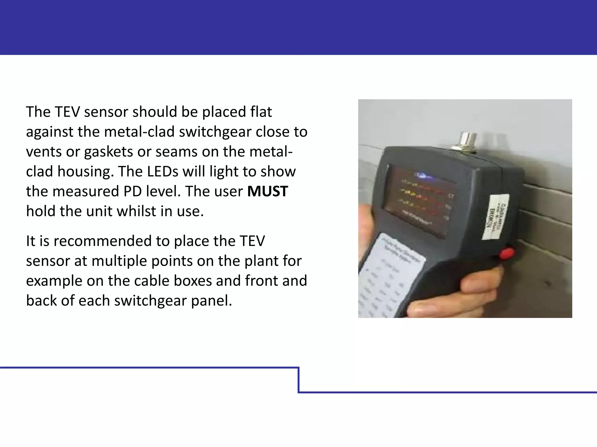
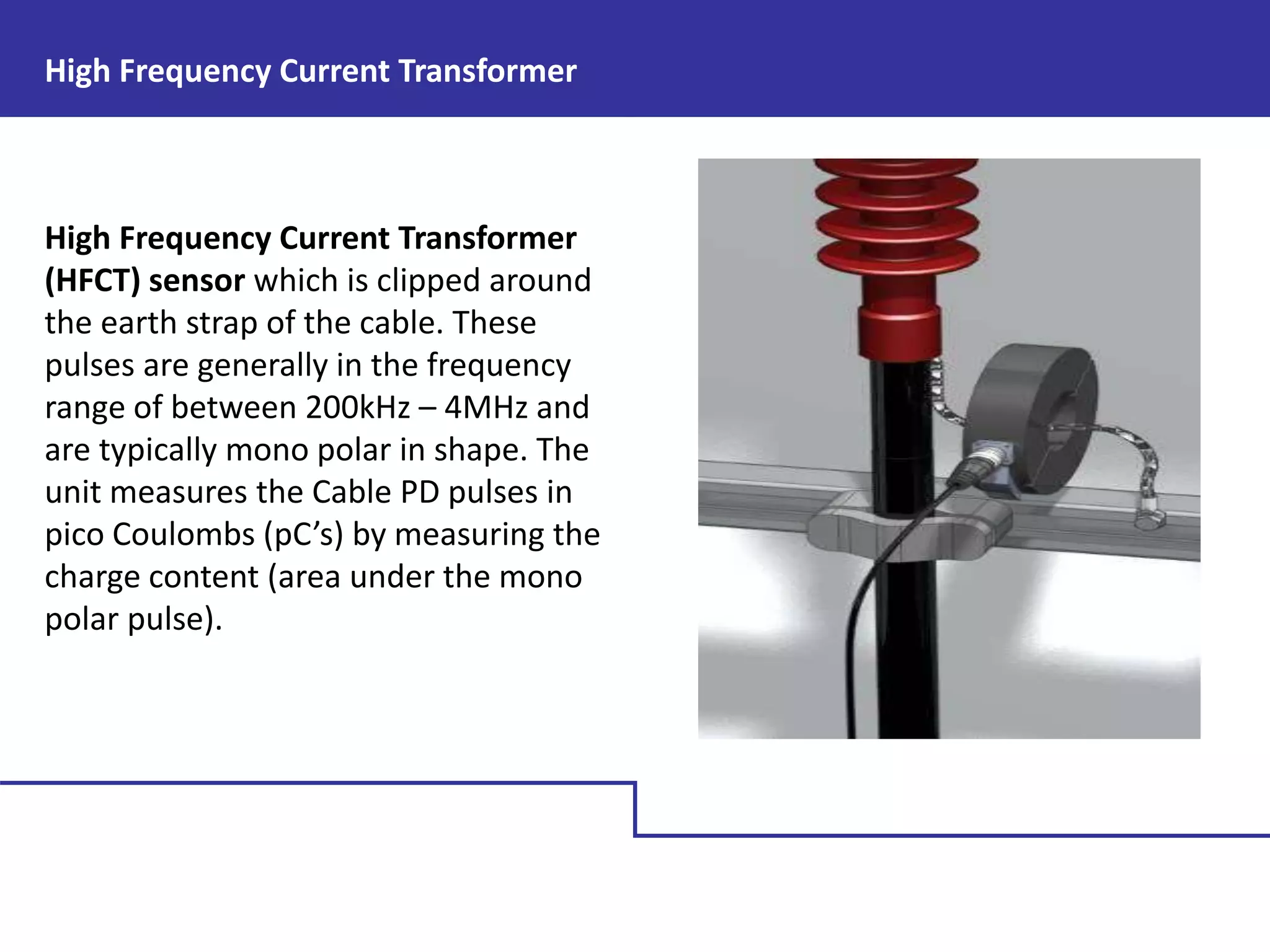
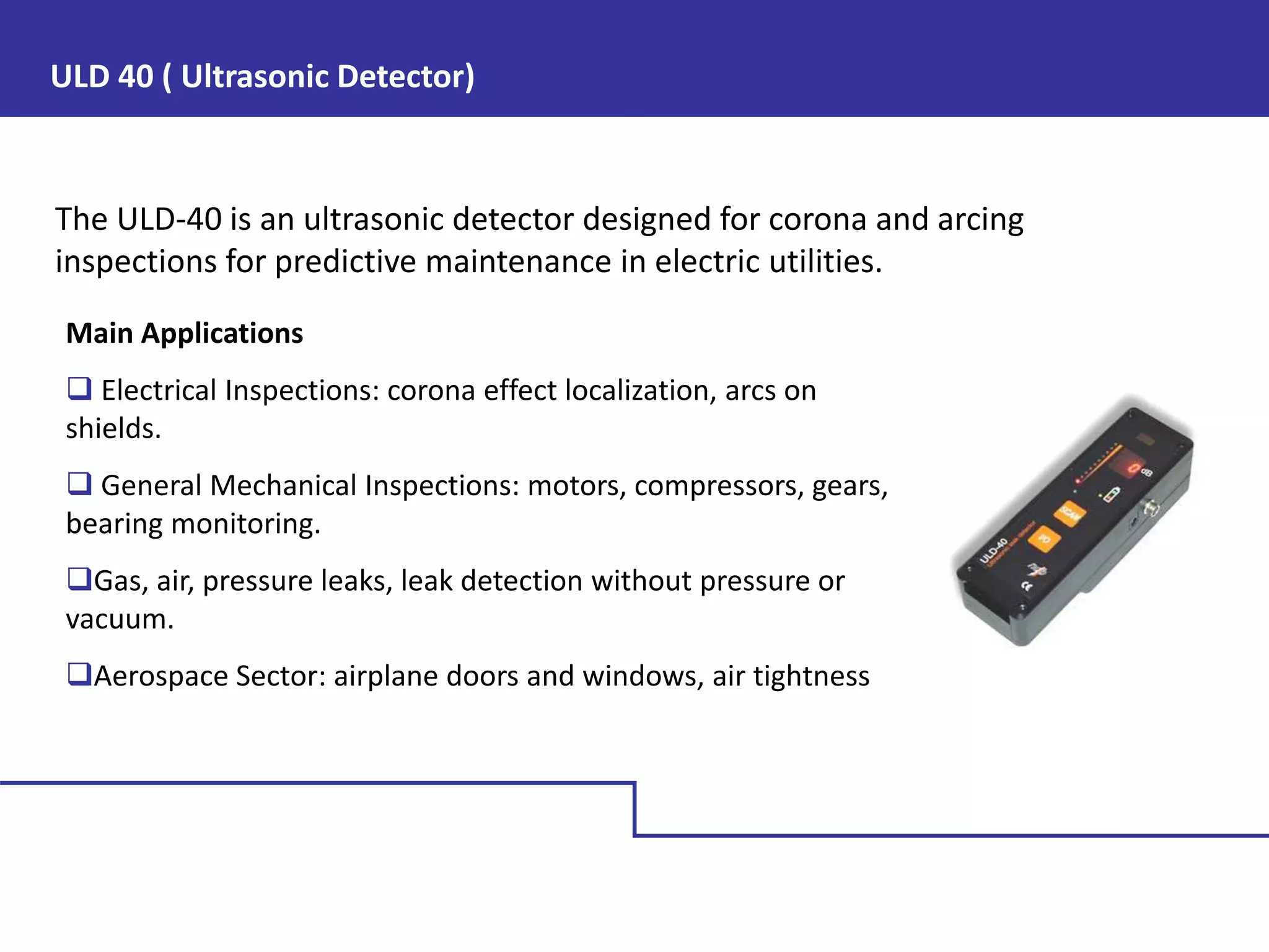
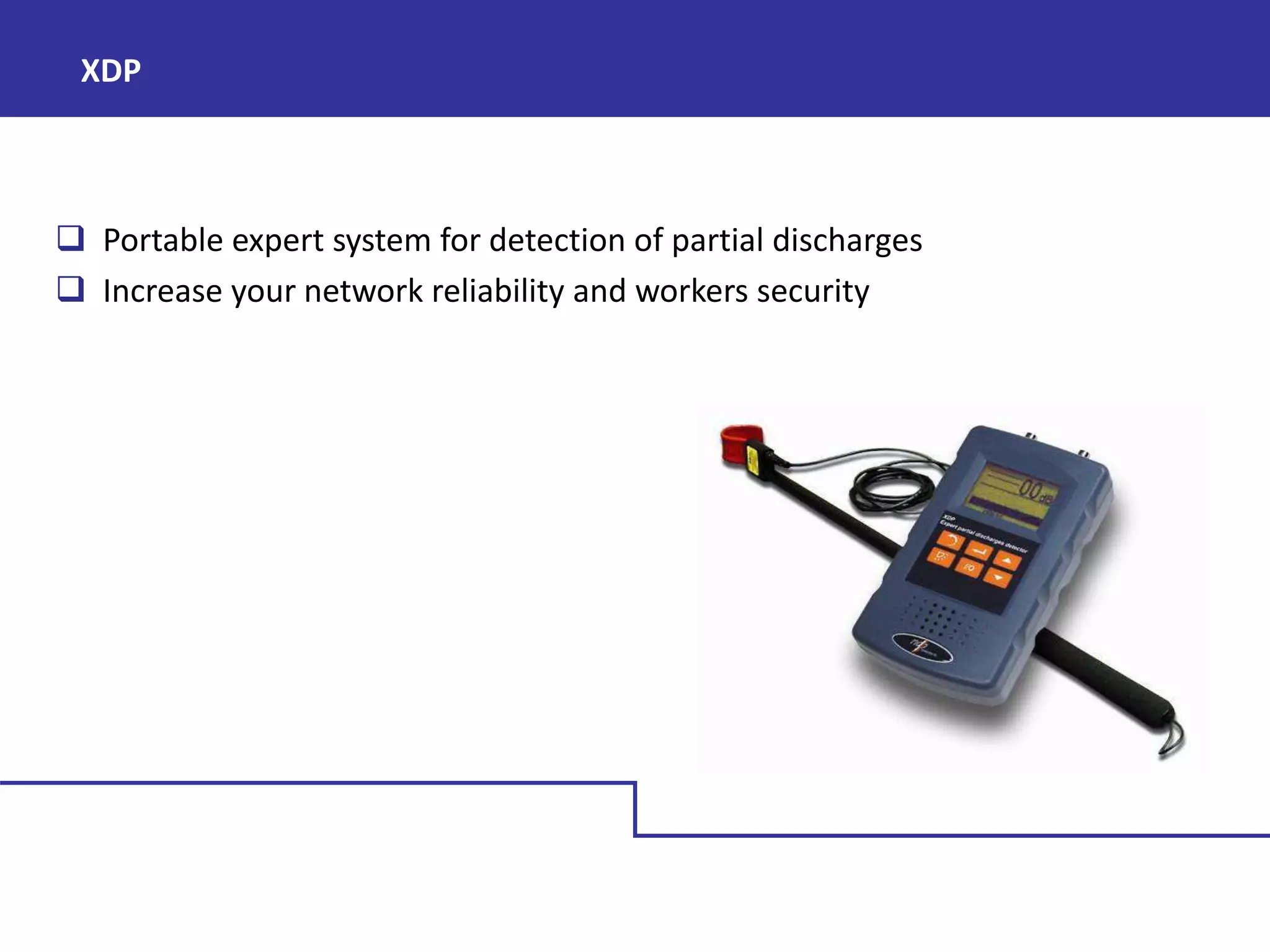
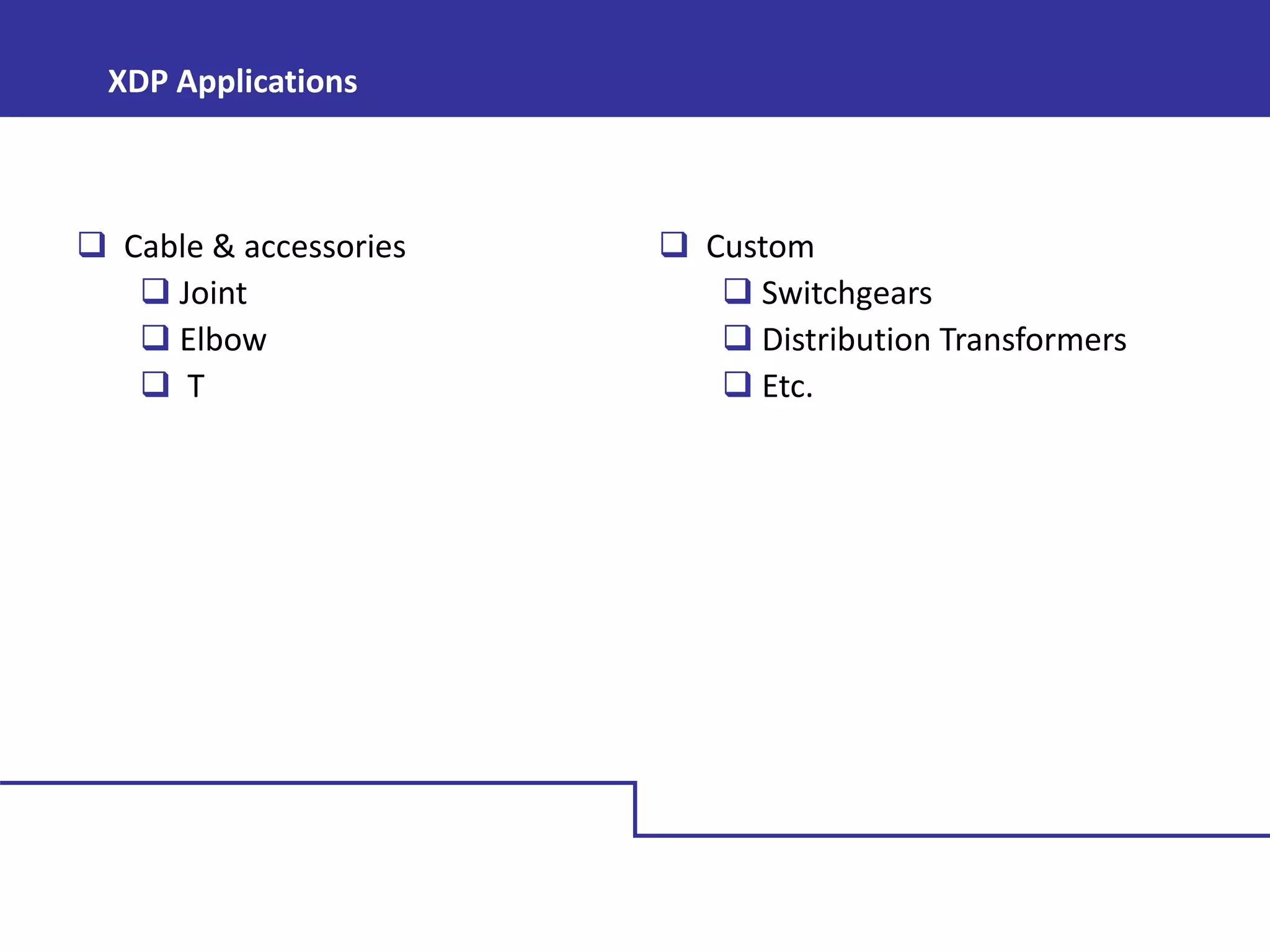
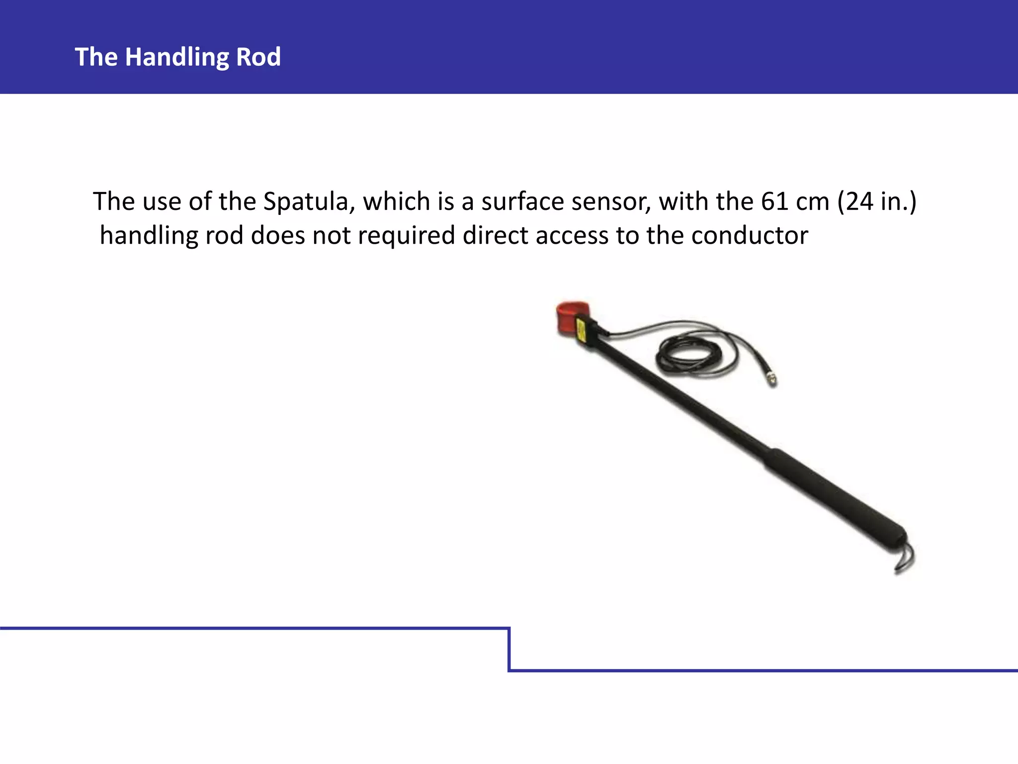
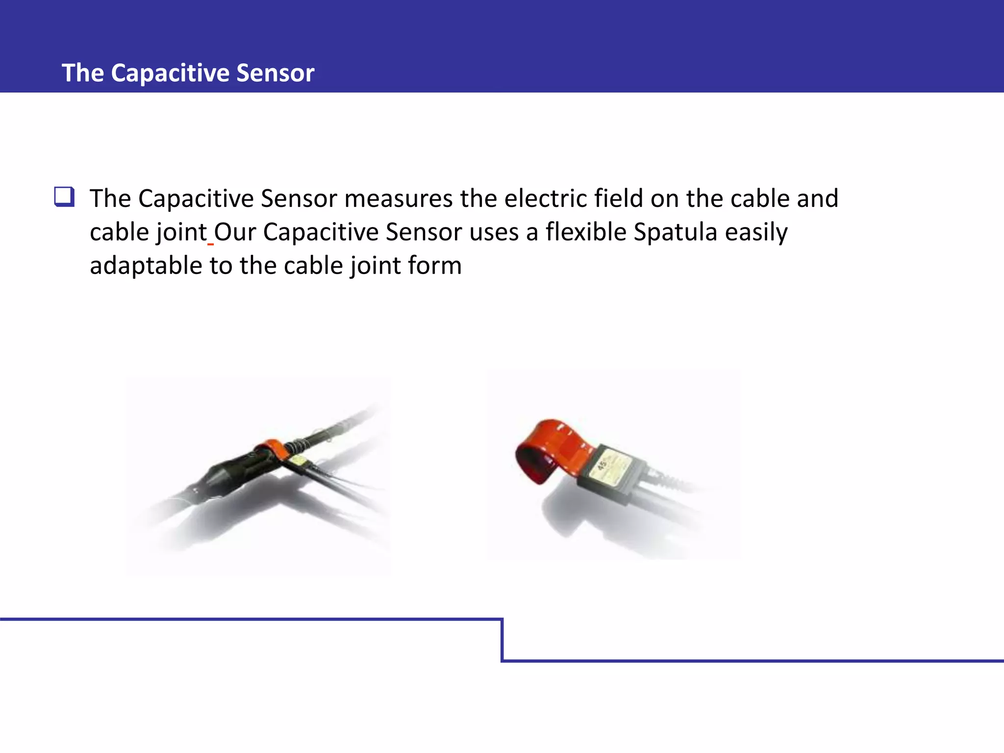
SlideShare a Scribd company logo
Predictive Maintenance of MV Switchgear with
Partial Discharge
R K Gupta
Principal Consulting Electrical Engineer (Power System)
Reliability Engineer
BE Electrical
Protection, Automation, PLC & SCADA, Level 3 MCSA, Colorado USA
IEC 60270 Section 3.1 Notes
“Partial discharges are in general a consequence of local electrical stress
concentrations in the insulation or on the surface of the insulation…”
..“Corona is a form of partial discharge that occurs in gaseous media around
conductors which are remote from solid or liquid insulation…”
..“Partial discharges are often accompanied by emission of sound, light, heat,
and chemical reactions…”
“Localized electrical discharge that only partially bridges the insulation
between conductors and which can or cannot occur adjacent to a conductor.”
Partial Discharge Test
IEEE Standard 400-2001 Notes
“Partial discharge measurement is an important method of assessing the
quality of the insulation of power cable system”
“A partial discharge is an electrical discharge (formation of a streamer or
arc) that does not bridge the entire space between two electrodes.”
“Partial discharges may occur in a “void…at a contaminant…or at the tip of
a well-developed water tree...”
Partial Discharge Test
Partial discharge Taxonomy
Three basic types of PD sources:
 Internal PD
 Surface PD
 Corona PD
Focus on
Internal Discharges
PD Inception Condition
 A free electron is available in the gas inside the void.
 Mechanisms that allow a free electron inside the gas:
a. Ionization by photon/gas molecule collision (background radiation)
b. Schottky emission of electrons from metal and /or dielectric surfaces
(electron injection).
 The external field, fE0, exceeds the inception field, Einc.
The free electron, accelerated by electric field, can trigger an electron
avalanche (PD).
Partial Discharge Process in Solid
Insulator /Air Insulator
 Solid insulators are manufactured to give an even distribution of electrical
stress between the conducting electrodes.
 Manufacturing processes invariably give rise to small cavities or voids in the
insulation bulk. These cavities are usually filled with a gas of lower breakdown
strength than the surrounding solid.
The permittivity of the gas is invariably lower than that of the solid insulation,
causing the field intensity in the cavity to be higher than that in the dielectric.
Therefore under the normal working stress of the insulation, the voltage across
the cavity may exceed the breakdown value and initiate electrical breakdown in
the void.
Equivalent circuit for cavity in insulator
A solid insulator of thickness d contains a
disc shaped cavity of thickness t and area
A, as shown fig. In the equivalent circuit
the capacitance Cc corresponds to the
cavity, Cb corresponds to the capacity of
the dielectric that is in series with Cc and
Ca is the capacitance of the rest of the
dielectric. Given that capacitance C, in
Farads/m2, is given by;
Where;
e0 = permittivity of free space = 8.854 x 10⁻¹² Fm-
1
er = relative permittivity
A = area between electrodes
d = separation of electrodes
Breakdown Strength in Cavity
If we assume that the gas in the cavity (of thickness t) in figure 1 has a relative
permittivity of approximately 1, then:
And,
As Cb and Cc essentially form a capacitive divider, the voltage across the cavity,
Vc, can be expressed as;
Substituting into the above equation gives;
Breakdown Strength in Cavity
Electrical field strength across the cavity (Ec) is given by the equation
Given that in most circumstances t << d and er is greater than 1, it can be seen
that electrical stress in the cavity is greater than that in the surrounding
insulation. This, coupled with the fact that the breakdown strength of the gas is
likely to be significantly lower than that of the insulation, makes the gas in the
void liable to breakdown under normal working conditions.
Breakdown Strength in Cavity
From the equations above it can be seen that the voltage across the dielectric
at which discharge activity will initiate in the cavity, Vai, is given by;
In practice voids in solid insulators are very often approximately spherical.
In this case the field in the void is given by;
Where erc = relative permittivity of gas
in void.
When er >> erc this approximates to:
Relative permittivity and breakdown strengths of some typical high voltage
HV Insulating Material
Voltage and Current in discharging
Cavity
Each time a discharge occurs in the cavity,
charge is transferred from one side of the
cavity to the other until the potential
difference across the cavity is too small to
maintain the discharge. When the insulator
is subject to a sinusoidal alternating voltage,
charge builds up within the void as the
applied voltage increases or decreases. This
causes a series of discharges with charge
first moving in one direction, then the other.
Figure 2 shows how the voltage and current
across a cavity changes with applied voltage.
The dotted curve shows the voltage that would occur across the cavity if the
discharges did not equalize the potential difference across the cavity. As the
voltage Vc reaches the value V+, a discharge takes place and the, the voltage Vc
collapses and the discharge extinguishes. The voltage across the cavity then starts
again increasing until it reaches V+ , when a new discharge occurs. In this way
several discharges may take place during the rising part of the applied voltage.
Similarly, on decreasing the applied voltage the cavity discharges as the voltage
across it reaches V-, In this way groups of discharges are generated by a single
cavity and give rise to positive and negative current pulses on raising and
decreasing the applied voltage respectively.
Voltage and Current in discharging
Cavity
DEGRADING EFFECT IN SOLID
INSULATION
When the gas in a cavity breaks down, the opposite surfaces of the insulation
momentarily become cathode and anode. Some of the electrons hitting the
anode are sufficiently energetic to break the chemical bonds of the insulation
surface. Similarly, bombardment of the cathode by positive ions may cause
damage by increasing the surface temperature and produce local thermal
instability. These degrading effects form small channels and pits in the surface
that can elongate through the insulation. In addition to the ionic
bombardment, chemical degradation may result from active discharge
products, like O3 or NO2, formed in the air by the discharges. The net effect is
slow erosion of the insulating material and a very gradual increase in the size
of the cavity
Electrical Trees
 Electrical trees are comprised of a series of interconnecting channels or discharge
paths with diameters ranging from less than a micron to tens of microns.
 Discharge activity in voids will eventually become centered at particular sites
producing deep cavities in the surface. The cavities grow in length along the discharge
axis and the energy of discharge impinging on their tips increases. This combined with
electrical stress concentration by virtue of their point like form, produces increasingly
intense electrical fields at the tips of the discharging cavities.
 Eventually the breakdown strength of the material in the immediate vicinity of the
tip is exceeded. Breakdown follows with the evaporation, in the space of a few
nanoseconds, of a small volume of material.
 This rapid conversion launches small shock waves into the insulation. These waves
create, in time, a structure of fine cracks extending into the insulation. Their name
comes from the dendritic patterns they from in the insulation.
Electrical trees emanate from points of stress enhancement
in insulation. This can be a metal inclusion or a protrusion on
a conductor but in practice they more usually originate from
a void. The exact process by which electrical trees propagate
is still not fully understood, however, it is generally accepted
as being a combination of mechanical and thermal effects.
There are two clear stages in the development of electrical
trees under the application of an alternating voltage, the
inception period, which may be considerable and a much
shorter formative period. Eventually the tree will bridge the
insulation. Discharges continue to occur without breakdown
because space charge sets up a reverse field in the channels
to counter the field between the electrodes. During this
period the channels slowly widen. Eventually the field can no
longer be maintained in the widened channels and
catastrophic breakdown occurs, creating a very large channel
though the insulation.
Electrical Trees
Tracking
 Tracking is the formation of a permanent conducting path across an insulator surface.
Usually the conduction path results from degradation of the insulation. For tracking to occur
the insulation must be a carbon based compound.
 Most high voltage plant is situated outside. In industrial areas, insulators become
contaminated with pollution and dirt from the atmosphere. Where substations are situated
near the sea, salt very quickly covers the plant. In the presence of moisture, these
contaminating layers gives rise to leakage current over the insulator surface. This heats the
surface and through evaporation causes interruption in the moisture film. Large potential
differences are generated over the gaps in the moisture film and small sparks can bridge the
gaps. Heat from the sparks causes carbonization of the insulation and leads to the formation
of permanent carbon tracks on the surface.
Tracking as a phenomenon severely limits the use of organic insulators in outdoor
environments. The rate of tracking depends on the structure of the polymers and can be
significantly reduced by adding appropriate fillers to the polymer which inhibit carbonization.
CORONA
Corona is a partial discharge in regards that gas
breakdown begins at a position of high electric
field but dies out as the electric field decreases
very rapidly as a function of distance from the
highly stressed position. The breakdown can die
out for two reasons;
The region of high field is too small to generate
a fully formed breakdown channel.
The field falls to such a low value, that even a
fully formed breakdown channel cannot
propagate.
Corona forms in partially ionised regions adjacent to conductors and causes a change in the electric field between the
conductor and the ground. In effect, it can be seen as an extension of the conductor. As such, it will effectively reduce
the capacitance between the conductor and ground, as their separation decreases. This causes a drop in the voltage
on the conductor, a potential difference between the conductor and the voltage source and, therefore, a current flow
from the voltage source to the conductor. The electric field in a corona is sufficiently high that when a free electron
occurs, that electron will, on average, generate more than one additional electron (and positive ion). So a corona is
full of positive and negative ions (electrons).
Thus when the field reduces to the extent that the original current ceases to flow, the electric field does not
immediately return to its previously high value. Before that can happen, the positive and negative ions must flow in
the field toward the negative and positive electrodes respectively. As the negative charges are in the form of
electrons, they can propagate sufficiently fast to contribute to the measured partial discharge signal. However
massive positive ions flow so slowly that they typically generate a very small current over a long period of time.
Thus a corona can be thought of as generating a PD signal though three mechanisms. First, the ionisation of a
channel, which tends to look like an extension of the conductor and therefore increases the capacitance of the
conductor to ground. Second rapid migration of electrons toward the positive electrode in a system where negative
charge flows as electrons. And thirdly, flow of positive ions which tends to be too slow to be detected by most PD
measuring systems. The time scale for the first two phenomena is nanoseconds to microseconds, while that for the
third phenomena can be milliseconds or more.
CORONA
Corona tends to be repetitive, as once the region is cleared of charge, it returns to the
conditions which generated it in the first place. Corona in air is sensitive to air velocity and
environmental conditions which affect space charge near the conductor.
In many gases, including air, corona generated by positive and negative voltages differ
substantially. This is due to the physical difference between negative charge carriers
(electrons) and positive charge carriers (positive ions). Electrons being light and mobile
gain kinetic energy very rapidly from an electric field, while positive ions are heavy and
much less mobile. The outside surface of molecules is made up of electrons, so violent
phenomena, which dislodge charge from a molecule, free an electron and simultaneously
create a heavy positive ion. In corona from a negative conductor, electrons propagate
away from the conductor in the direction of corona growth. Thus they can create further
electrons through molecular collisions. In corona from a positive conductor, the electrons
propagate towards the conductor and away from the direction of corona growth. In this
case, electrons are generally detached ahead of the corona tip by photons generated
within the corona.
CORONA
Water Trees
A water tree is a bush or fan like structure developing like an electrical tree, from points of
stress enhancement. Water trees cause a reduction in the insulation's breakdown stress level
which encourages breakdown. Electrical trees can, on occasion, be initiated from a water tree
speeding the breakdown process.
Water trees are more diffuse than electrical trees and
generally grow at lower electrical stresses. Two types of
water tree have been recognized according to where the
tree initiates, ‘bow-tie’ trees and ‘vented’ trees.
Bow-tie trees are initiated in the bulk of the insulating
material, often from a void, and grow towards the
conducting screens. They clearly derive their name from
the pattern they form. Vented trees grow from one of
the conducting screens into the insulation bulk
PD Testing Methods
 Online Partial Discharge Testing
Ultrasonic
Transient Earth Voltage
High Frequency Current Transformer
Electrical Method (Inductive & Capacitive)
 Offline Partial Discharge Testing
Capacitance Voltage Divider( CVD) method
Ultrasonic
Electrical arcs in the air and corona effects emit sounds and ultrasounds. The basic
electrical problems that produce distinct ultrasound waves that can be detected
by Ultrasonic Testing include partial discharge, corona and tracking. Ultrasonic
measurement is most powerful on a comparative basis and will significantly
increase the reliability of correct detection of partial discharge.
Ranges of Ultrasonic detection
Center frequency 40 KHz
Bandwidth 38kHz-48kHz
Acoustic Airborne
Airborne acoustic (ultrasonic) radiation through air from corona and surface
discharges in the plant
Ultrasonic / Acoustic Airborne
Test Method
Background Noise Measurement
If any reading is made with the sensor flat on a surface (not over a vent or
air gap) this can be discounted as background noise.
AA/Ultrasonic Sensor Attachment Requirements
 There must be a clear air path (line of sight) from the sensor to the
discharge source, i.e. a vent or hole in the plant housing.
 Fully enclosed air insulated switchgear with no grills, vents, air gaps etc,
will not be suitable for Airborne Acoustic measurements.
Transient Earth Voltage
Transient Earth Voltage (TEV) PD signals
are generated by internal partial discharges
in switchgear, cable terminations, motors
and transformers. TEV signals are in a
higher frequency range of between 4MHz –
100MHz and are oscillatory in general. The
resultant PD signals are measured in dB
(decibels), as is the convention for on-line
s w i t c h g e a r t e s t i n g .
Background Noise Measurement
TEV measurements can be affected by background electrical noise in the
substation. Sources include:
Power electronic switching, e.g. from DC power supplies.
Corona from outdoor switchyards.
High frequency communication systems, e.g. two-way radios
TEV Test Method
The TEV sensor should be placed flat
against the metal-clad switchgear close to
vents or gaskets or seams on the metal-
clad housing. The LEDs will light to show
the measured PD level. The user MUST
hold the unit whilst in use.
It is recommended to place the TEV
sensor at multiple points on the plant for
example on the cable boxes and front and
back of each switchgear panel.
TEV Test Method
High Frequency Current Transformer
(HFCT) sensor which is clipped around
the earth strap of the cable. These
pulses are generally in the frequency
range of between 200kHz – 4MHz and
are typically mono polar in shape. The
unit measures the Cable PD pulses in
pico Coulombs (pC’s) by measuring the
charge content (area under the mono
polar pulse).
High Frequency Current Transformer
Procedure for HFCT PD Measurement
Background Noise Measurement
HFCT measurements can be affected by background electrical noise sources
inside and outside the substation. Sources include:
Radio frequency interference from local radio transmission
Corona from outdoor switchyards.
To measure the background noise level, attach the HFCT to the earthing
conduit of a de-energized feeder, or a nearby LV earth.
Electrical Method
Capacitive Sensor
The Capacitive Sensor measures the electric field on the cable and cable joint.
Sensors are designed to detects the quick variations of electrical fields caused by
PD. The probe is a coated metal plate that create a capacitor between the cable
and the plate. This capacitive coupler allows to read the PD activity on surface.
The PD signal is detected by a capacitive probe, then amplified by the
equipment in radio frequency bandwidth. The signal amplitude is proportional
to the discharge energy.
ULD 40 ( Ultrasonic Detector)
The ULD-40 is an ultrasonic detector designed for corona and arcing
inspections for predictive maintenance in electric utilities.
Main Applications
 Electrical Inspections: corona effect localization, arcs on
shields.
 General Mechanical Inspections: motors, compressors, gears,
bearing monitoring.
Gas, air, pressure leaks, leak detection without pressure or
vacuum.
Aerospace Sector: airplane doors and windows, air tightness
Detection of Electrical Arcs and Corona
Effects
Electrical arcs in the air and corona
effects emit sounds and ultrasounds. The
role of the ULD-40 consists of capturing
emitted ultrasounds and of translating
them into the audible range. The ULD-40
accurately pinpoints and identifies
corona effects and arcs that may be
encountered on any type of high voltage
installation simply by scanning around
the suspected area.
 Portable expert system for detection of partial discharges
 Increase your network reliability and workers security
XDP
 It is an instrument that enables to quantify the intensity of the high
frequency electric field signal emitted by the partial discharge of a
component, and to translate it into decibels (dB)
 A decibel (dB) is a unit that expresses the intensity of a signal in
relations to a reference on the logarithmic scale
XDP
With the XDP
 Follow up on ageing process of the critical components’ insulation
 Perform Quality Control of the insulators during installation or repair
 Safety control prior to work on energize equipment
XDP Advantages
 Portable
 Verification done under normal charge of the electric network – No
service interruption
 Quick readings
 Very sensible
 Pinpoints the problem
 Our 3rd generation of PD Detector
XDP Technical Specifications
 Peak measurement value in dB relative to 15 picoCoulomb
 Peak detection with a fast numeric circuit
 Fast numeric processor (DSP) for instant analysis results
 Wave’s shape inspection in high frequency to determine PD proximity
XDP Technical Specifications…
 LCD (Liquid Crystal Display) displays wave form
and dB reading
 Easy to read, big letter casings
 Upload/download capability
 PC (Windows) interface for PD readings
analysis/trending
XDP Technical Specifications…
 Dynamic range of 40 dB
 Up to 64 readings recording capability
 Bandwidth of 300 kHz to 70 MHz
 Sampling frequency of 30 MHz
 Sampling period of 16 cycles (50 or 60 HZ)
 Built-in Real Time Clock
XDP Technical Specifications…
 Keeps in memory up to 10 PD signatures for quick PD recognition
 Quick auto-verification procedure for high reliability
 8 hour battery autonomy
 The smaller PD Expert System on the market
 203 X 114 X 51 mm (8 X 4.5 X 2 in.)
 0,86 kg (1,9 lbs)
XDP Applications
 Cable & accessories
 Joint
 Elbow
 T
 Custom
 Switchgears
 Distribution Transformers
 Etc.
The Handling Rod
The use of the Spatula, which is a surface sensor, with the 61 cm (24 in.)
handling rod does not required direct access to the conductor
The Capacitive Sensor
 The Capacitive Sensor measures the electric field on the cable and
cable joint Our Capacitive Sensor uses a flexible Spatula easily
adaptable to the cable joint form
How it works
 The XDP detects the quick variations of electrical fields caused by PD
 The probe is a coated metal plate that create a capacitor between the
cable and the plate
 This capacitive coupler allows to read the PD activity on surface
 It is moved along joints and on cable insulation jacket, in order to
detect the presence of PD activity
 The PD signal is detected by a capacitive probe, then amplified by the XDP
in radio frequency bandwidth
 The signal amplitude is proportional to the discharge energy
 The energy is displayed on the XDP in dB (relative value)
How to use the Spatula Sensor
 Check the reference value on a regular basis to make sure that the XDP
works well
 Turn off the XDP
 Connect the reference module
 Connect the Spatula Sensor
 Place the sensor on the module in a way to make it cling around it
as much as possible
Check the reference value…
 Activate the XDP
 On the numeric display, you must read the displayed value on the sensor’s
case
 This technique will allow you to detect a PD activity even in an
environment with normal to high ambient noise (12 – 20 dB)
 Always adjust the spatula the way it fit as much as possible around the
cable and cable joint
 Always use the handling rod
Inductive Probe
 Applications
 Terminations
 Shielded cables
 Cable joints with grounding braid
A B
C
D
Quality control of a 12 dB ambient noise
splice
 Without defect
 A = 10dB
 B = 12dB
 C = 12dB
 D = 10dB
 With defect
 A = 12dB
 B = 14dB
 C = 34dB
 D = 16dB
PD activities level classification
 Level 1: Free of Partial Discharge activity. No necessary action at this time.
Retest within 12 to 18 months (< 12dB)
 Level 2: Moderate levels of Partial Discharge activity. Retest within 1 year
(12 – 20dB)
 Level 3: High level of Partial Discharge activity. Repair or replacement
required (20 – 35dB)
PD activities level classification…
 Level 4: Very high level of Partial Discharge activity (> 35dB)
 We strongly recommend to restrict the access to the area
 Repair or replacement required as soon as possible
Thank you

More Related Content

What's hot

Solid breakdown (2) (1)
Solid breakdown (2) (1)Solid breakdown (2) (1)
Solid breakdown (2) (1)
mukund mukund.m
 
Cable fault location methods (Megger)
Cable fault location methods (Megger)Cable fault location methods (Megger)
Cable fault location methods (Megger)
AHMED MOHAMED HEGAB
 
Guidelines for Unconventional Partial Discharge Measurement (CIGRE 444)
Guidelines for Unconventional Partial Discharge Measurement (CIGRE 444)Guidelines for Unconventional Partial Discharge Measurement (CIGRE 444)
Guidelines for Unconventional Partial Discharge Measurement (CIGRE 444)
AHMED MOHAMED HEGAB
 
System neutral-earthing
System neutral-earthingSystem neutral-earthing
System neutral-earthing
azzaabo
 
BREAKDOWN IN LIQUIDS_NDS
BREAKDOWN IN LIQUIDS_NDSBREAKDOWN IN LIQUIDS_NDS
BREAKDOWN IN LIQUIDS_NDS
Niraj Solanki
 
Sheath Fault Location On Power Cables - Sheath Testing, Sheath Fault Location...
Sheath Fault Location On Power Cables - Sheath Testing, Sheath Fault Location...Sheath Fault Location On Power Cables - Sheath Testing, Sheath Fault Location...
Sheath Fault Location On Power Cables - Sheath Testing, Sheath Fault Location...
Thorne & Derrick International
 
Mechanism for breakdown for
Mechanism for breakdown forMechanism for breakdown for
Mechanism for breakdown for
vishalgohel12195
 
POLLUTION TEST OF NATURALLY AND ARTIFICIALLY CONTAMINATED INSULATORS
POLLUTION TEST OF NATURALLY AND ARTIFICIALLY CONTAMINATED INSULATORSPOLLUTION TEST OF NATURALLY AND ARTIFICIALLY CONTAMINATED INSULATORS
POLLUTION TEST OF NATURALLY AND ARTIFICIALLY CONTAMINATED INSULATORS
Power System Operation
 
ELECTROMECHANICAL BREAKDOWN|BREAKDOWN IN SOLIDS|HIGH VOLTAGE ENGINEERING
ELECTROMECHANICAL BREAKDOWN|BREAKDOWN IN SOLIDS|HIGH VOLTAGE ENGINEERINGELECTROMECHANICAL BREAKDOWN|BREAKDOWN IN SOLIDS|HIGH VOLTAGE ENGINEERING
ELECTROMECHANICAL BREAKDOWN|BREAKDOWN IN SOLIDS|HIGH VOLTAGE ENGINEERING
Prasant Kumar
 
BREAKDOWN MECHANISM OF LIQUID DIELECTRICS (ALL METHODS))|BREAKDOWN IN LIQUIDS...
BREAKDOWN MECHANISM OF LIQUID DIELECTRICS (ALL METHODS))|BREAKDOWN IN LIQUIDS...BREAKDOWN MECHANISM OF LIQUID DIELECTRICS (ALL METHODS))|BREAKDOWN IN LIQUIDS...
BREAKDOWN MECHANISM OF LIQUID DIELECTRICS (ALL METHODS))|BREAKDOWN IN LIQUIDS...
Prasant Kumar
 
Electrostatic fields and field stress control
Electrostatic fields and field stress controlElectrostatic fields and field stress control
Electrostatic fields and field stress control
vhasmukh96
 
Dielectric breakdown in liquids purity
Dielectric breakdown in liquids purityDielectric breakdown in liquids purity
Dielectric breakdown in liquids purity
Santosh Verma
 
Partial discharge switchgear ea tech
Partial discharge switchgear ea techPartial discharge switchgear ea tech
Partial discharge switchgear ea tech
Mauritz Roni Gabe Manurung
 
Power transformer losses
Power transformer lossesPower transformer losses
Power transformer losses
Leonardo ENERGY
 
Hv module 3 Impulse voltage generation
Hv module 3 Impulse voltage generationHv module 3 Impulse voltage generation
Hv module 3 Impulse voltage generation
Asha Anu Kurian
 
BREAKDOWN OF SOLID DIELECTRICS|BREAKDOWN IN SOLIDS|HIGH VOLTAGE ENGINEERINGo...
 BREAKDOWN OF SOLID DIELECTRICS|BREAKDOWN IN SOLIDS|HIGH VOLTAGE ENGINEERINGo... BREAKDOWN OF SOLID DIELECTRICS|BREAKDOWN IN SOLIDS|HIGH VOLTAGE ENGINEERINGo...
BREAKDOWN OF SOLID DIELECTRICS|BREAKDOWN IN SOLIDS|HIGH VOLTAGE ENGINEERINGo...
Prasant Kumar
 
Streamer theory
Streamer theoryStreamer theory
Streamer theory
Mohammed Almatri
 
Lightning Arrestar
Lightning ArrestarLightning Arrestar
Lightning Arrestar
younistanzeela
 
Transformer & OLTC
Transformer & OLTCTransformer & OLTC
Transformer & OLTCRohit Dave
 
Circuit Breakers
Circuit BreakersCircuit Breakers
Circuit Breakers
Ameen San
 

What's hot (20)

Solid breakdown (2) (1)
Solid breakdown (2) (1)Solid breakdown (2) (1)
Solid breakdown (2) (1)
 
Cable fault location methods (Megger)
Cable fault location methods (Megger)Cable fault location methods (Megger)
Cable fault location methods (Megger)
 
Guidelines for Unconventional Partial Discharge Measurement (CIGRE 444)
Guidelines for Unconventional Partial Discharge Measurement (CIGRE 444)Guidelines for Unconventional Partial Discharge Measurement (CIGRE 444)
Guidelines for Unconventional Partial Discharge Measurement (CIGRE 444)
 
System neutral-earthing
System neutral-earthingSystem neutral-earthing
System neutral-earthing
 
BREAKDOWN IN LIQUIDS_NDS
BREAKDOWN IN LIQUIDS_NDSBREAKDOWN IN LIQUIDS_NDS
BREAKDOWN IN LIQUIDS_NDS
 
Sheath Fault Location On Power Cables - Sheath Testing, Sheath Fault Location...
Sheath Fault Location On Power Cables - Sheath Testing, Sheath Fault Location...Sheath Fault Location On Power Cables - Sheath Testing, Sheath Fault Location...
Sheath Fault Location On Power Cables - Sheath Testing, Sheath Fault Location...
 
Mechanism for breakdown for
Mechanism for breakdown forMechanism for breakdown for
Mechanism for breakdown for
 
POLLUTION TEST OF NATURALLY AND ARTIFICIALLY CONTAMINATED INSULATORS
POLLUTION TEST OF NATURALLY AND ARTIFICIALLY CONTAMINATED INSULATORSPOLLUTION TEST OF NATURALLY AND ARTIFICIALLY CONTAMINATED INSULATORS
POLLUTION TEST OF NATURALLY AND ARTIFICIALLY CONTAMINATED INSULATORS
 
ELECTROMECHANICAL BREAKDOWN|BREAKDOWN IN SOLIDS|HIGH VOLTAGE ENGINEERING
ELECTROMECHANICAL BREAKDOWN|BREAKDOWN IN SOLIDS|HIGH VOLTAGE ENGINEERINGELECTROMECHANICAL BREAKDOWN|BREAKDOWN IN SOLIDS|HIGH VOLTAGE ENGINEERING
ELECTROMECHANICAL BREAKDOWN|BREAKDOWN IN SOLIDS|HIGH VOLTAGE ENGINEERING
 
BREAKDOWN MECHANISM OF LIQUID DIELECTRICS (ALL METHODS))|BREAKDOWN IN LIQUIDS...
BREAKDOWN MECHANISM OF LIQUID DIELECTRICS (ALL METHODS))|BREAKDOWN IN LIQUIDS...BREAKDOWN MECHANISM OF LIQUID DIELECTRICS (ALL METHODS))|BREAKDOWN IN LIQUIDS...
BREAKDOWN MECHANISM OF LIQUID DIELECTRICS (ALL METHODS))|BREAKDOWN IN LIQUIDS...
 
Electrostatic fields and field stress control
Electrostatic fields and field stress controlElectrostatic fields and field stress control
Electrostatic fields and field stress control
 
Dielectric breakdown in liquids purity
Dielectric breakdown in liquids purityDielectric breakdown in liquids purity
Dielectric breakdown in liquids purity
 
Partial discharge switchgear ea tech
Partial discharge switchgear ea techPartial discharge switchgear ea tech
Partial discharge switchgear ea tech
 
Power transformer losses
Power transformer lossesPower transformer losses
Power transformer losses
 
Hv module 3 Impulse voltage generation
Hv module 3 Impulse voltage generationHv module 3 Impulse voltage generation
Hv module 3 Impulse voltage generation
 
BREAKDOWN OF SOLID DIELECTRICS|BREAKDOWN IN SOLIDS|HIGH VOLTAGE ENGINEERINGo...
 BREAKDOWN OF SOLID DIELECTRICS|BREAKDOWN IN SOLIDS|HIGH VOLTAGE ENGINEERINGo... BREAKDOWN OF SOLID DIELECTRICS|BREAKDOWN IN SOLIDS|HIGH VOLTAGE ENGINEERINGo...
BREAKDOWN OF SOLID DIELECTRICS|BREAKDOWN IN SOLIDS|HIGH VOLTAGE ENGINEERINGo...
 
Streamer theory
Streamer theoryStreamer theory
Streamer theory
 
Lightning Arrestar
Lightning ArrestarLightning Arrestar
Lightning Arrestar
 
Transformer & OLTC
Transformer & OLTCTransformer & OLTC
Transformer & OLTC
 
Circuit Breakers
Circuit BreakersCircuit Breakers
Circuit Breakers
 

Similar to Partial Discharge Test - Switchgear

1502957341lectrure_3_KUET [Autosaved] [Autosaved].pptx
1502957341lectrure_3_KUET [Autosaved] [Autosaved].pptx1502957341lectrure_3_KUET [Autosaved] [Autosaved].pptx
1502957341lectrure_3_KUET [Autosaved] [Autosaved].pptx
Tajmun1
 
Chapter Five Corona and Overhead line Insulators.pptx
Chapter Five Corona and Overhead line Insulators.pptxChapter Five Corona and Overhead line Insulators.pptx
Chapter Five Corona and Overhead line Insulators.pptx
ssuserc8d444
 
Measurenments of DC Resistivity
Measurenments of DC ResistivityMeasurenments of DC Resistivity
Measurenments of DC Resistivity
Engr Muhammad Imran
 
Lecture no 3 switchgears bt255
Lecture no 3 switchgears bt255Lecture no 3 switchgears bt255
Lecture no 3 switchgears bt255
Fazal Ur Rehman
 
Highvolatage enegineering updated.pptx
Highvolatage enegineering updated.pptxHighvolatage enegineering updated.pptx
Highvolatage enegineering updated.pptx
LavanyaUj
 
Protection & switchgear
Protection & switchgear   Protection & switchgear
Protection & switchgear
johny renoald
 
Mos short channel effects
Mos short channel effectsMos short channel effects
Mos short channel effects
Sri Konduru
 
Breakdown due to Internal Discharges and Surface Breakdown
Breakdown due to Internal Discharges and Surface BreakdownBreakdown due to Internal Discharges and Surface Breakdown
Breakdown due to Internal Discharges and Surface Breakdown
Asim Raza
 
Surge arrester
Surge arresterSurge arrester
Surge arrester
pratikguptateddy
 
Type and application of dielectric
Type and application of dielectricType and application of dielectric
Type and application of dielectric
raj_sevak
 
Dielectric Materials types & properties, adavantages, lossess
Dielectric Materials types & properties, adavantages, lossessDielectric Materials types & properties, adavantages, lossess
Dielectric Materials types & properties, adavantages, lossess
SANGRAMJADHAV49
 
Circuit breaker arc phenomena
Circuit breaker arc phenomenaCircuit breaker arc phenomena
Circuit breaker arc phenomenaBhavin Pradhan
 
Short channel modified
Short channel modifiedShort channel modified
Short channel modified
MOHAMMED FURQHAN
 
Dielectric Material, Properties & Applications
Dielectric Material, Properties & ApplicationsDielectric Material, Properties & Applications
Dielectric Material, Properties & Applications
SANGRAMJADHAV49
 
Short channel effects
Short channel effectsShort channel effects
Short channel effects
aditiagrawal97
 
EE6701 - HVE
EE6701 - HVEEE6701 - HVE
60928603-f15b-489b-b037-8ce97a839e8f-.pptx
60928603-f15b-489b-b037-8ce97a839e8f-.pptx60928603-f15b-489b-b037-8ce97a839e8f-.pptx
60928603-f15b-489b-b037-8ce97a839e8f-.pptx
RintuKurian3
 
Short Channel Effect In MOSFET
Short Channel Effect In MOSFETShort Channel Effect In MOSFET
Short Channel Effect In MOSFET
Sudhanshu Srivastava
 
Dielectric materials by vijayabasker 22ECR231.pptx
Dielectric materials by vijayabasker 22ECR231.pptxDielectric materials by vijayabasker 22ECR231.pptx
Dielectric materials by vijayabasker 22ECR231.pptx
VIJAYABASKARS22ECR23
 
Circuit breakers
Circuit breakersCircuit breakers
Circuit breakers
Adnan Sayed
 

Similar to Partial Discharge Test - Switchgear (20)

1502957341lectrure_3_KUET [Autosaved] [Autosaved].pptx
1502957341lectrure_3_KUET [Autosaved] [Autosaved].pptx1502957341lectrure_3_KUET [Autosaved] [Autosaved].pptx
1502957341lectrure_3_KUET [Autosaved] [Autosaved].pptx
 
Chapter Five Corona and Overhead line Insulators.pptx
Chapter Five Corona and Overhead line Insulators.pptxChapter Five Corona and Overhead line Insulators.pptx
Chapter Five Corona and Overhead line Insulators.pptx
 
Measurenments of DC Resistivity
Measurenments of DC ResistivityMeasurenments of DC Resistivity
Measurenments of DC Resistivity
 
Lecture no 3 switchgears bt255
Lecture no 3 switchgears bt255Lecture no 3 switchgears bt255
Lecture no 3 switchgears bt255
 
Highvolatage enegineering updated.pptx
Highvolatage enegineering updated.pptxHighvolatage enegineering updated.pptx
Highvolatage enegineering updated.pptx
 
Protection & switchgear
Protection & switchgear   Protection & switchgear
Protection & switchgear
 
Mos short channel effects
Mos short channel effectsMos short channel effects
Mos short channel effects
 
Breakdown due to Internal Discharges and Surface Breakdown
Breakdown due to Internal Discharges and Surface BreakdownBreakdown due to Internal Discharges and Surface Breakdown
Breakdown due to Internal Discharges and Surface Breakdown
 
Surge arrester
Surge arresterSurge arrester
Surge arrester
 
Type and application of dielectric
Type and application of dielectricType and application of dielectric
Type and application of dielectric
 
Dielectric Materials types & properties, adavantages, lossess
Dielectric Materials types & properties, adavantages, lossessDielectric Materials types & properties, adavantages, lossess
Dielectric Materials types & properties, adavantages, lossess
 
Circuit breaker arc phenomena
Circuit breaker arc phenomenaCircuit breaker arc phenomena
Circuit breaker arc phenomena
 
Short channel modified
Short channel modifiedShort channel modified
Short channel modified
 
Dielectric Material, Properties & Applications
Dielectric Material, Properties & ApplicationsDielectric Material, Properties & Applications
Dielectric Material, Properties & Applications
 
Short channel effects
Short channel effectsShort channel effects
Short channel effects
 
EE6701 - HVE
EE6701 - HVEEE6701 - HVE
EE6701 - HVE
 
60928603-f15b-489b-b037-8ce97a839e8f-.pptx
60928603-f15b-489b-b037-8ce97a839e8f-.pptx60928603-f15b-489b-b037-8ce97a839e8f-.pptx
60928603-f15b-489b-b037-8ce97a839e8f-.pptx
 
Short Channel Effect In MOSFET
Short Channel Effect In MOSFETShort Channel Effect In MOSFET
Short Channel Effect In MOSFET
 
Dielectric materials by vijayabasker 22ECR231.pptx
Dielectric materials by vijayabasker 22ECR231.pptxDielectric materials by vijayabasker 22ECR231.pptx
Dielectric materials by vijayabasker 22ECR231.pptx
 
Circuit breakers
Circuit breakersCircuit breakers
Circuit breakers
 

More from RajuGupta88

OFFLINE MOTOR TEST R K GUPTA
OFFLINE MOTOR TEST R K GUPTAOFFLINE MOTOR TEST R K GUPTA
OFFLINE MOTOR TEST R K GUPTA
RajuGupta88
 
Condition Based Asset Management R K Gupta
Condition Based Asset Management R K GuptaCondition Based Asset Management R K Gupta
Condition Based Asset Management R K Gupta
RajuGupta88
 
TRANSFORMER TESTING DISSOLVED GAS ANALYSIS
TRANSFORMER TESTING DISSOLVED GAS ANALYSISTRANSFORMER TESTING DISSOLVED GAS ANALYSIS
TRANSFORMER TESTING DISSOLVED GAS ANALYSIS
RajuGupta88
 
TRANSFORMER TEST acceptance criteria
TRANSFORMER TEST acceptance criteriaTRANSFORMER TEST acceptance criteria
TRANSFORMER TEST acceptance criteria
RajuGupta88
 
TRANSFORMER SAMPLE REPORT DGA PHYSICAL CONDITION
TRANSFORMER SAMPLE REPORT DGA PHYSICAL CONDITION TRANSFORMER SAMPLE REPORT DGA PHYSICAL CONDITION
TRANSFORMER SAMPLE REPORT DGA PHYSICAL CONDITION
RajuGupta88
 
Motor Current Signature Analysis R K Gupta
Motor Current Signature Analysis R K GuptaMotor Current Signature Analysis R K Gupta
Motor Current Signature Analysis R K Gupta
RajuGupta88
 

More from RajuGupta88 (6)

OFFLINE MOTOR TEST R K GUPTA
OFFLINE MOTOR TEST R K GUPTAOFFLINE MOTOR TEST R K GUPTA
OFFLINE MOTOR TEST R K GUPTA
 
Condition Based Asset Management R K Gupta
Condition Based Asset Management R K GuptaCondition Based Asset Management R K Gupta
Condition Based Asset Management R K Gupta
 
TRANSFORMER TESTING DISSOLVED GAS ANALYSIS
TRANSFORMER TESTING DISSOLVED GAS ANALYSISTRANSFORMER TESTING DISSOLVED GAS ANALYSIS
TRANSFORMER TESTING DISSOLVED GAS ANALYSIS
 
TRANSFORMER TEST acceptance criteria
TRANSFORMER TEST acceptance criteriaTRANSFORMER TEST acceptance criteria
TRANSFORMER TEST acceptance criteria
 
TRANSFORMER SAMPLE REPORT DGA PHYSICAL CONDITION
TRANSFORMER SAMPLE REPORT DGA PHYSICAL CONDITION TRANSFORMER SAMPLE REPORT DGA PHYSICAL CONDITION
TRANSFORMER SAMPLE REPORT DGA PHYSICAL CONDITION
 
Motor Current Signature Analysis R K Gupta
Motor Current Signature Analysis R K GuptaMotor Current Signature Analysis R K Gupta
Motor Current Signature Analysis R K Gupta
 

Recently uploaded

Sachpazis:Terzaghi Bearing Capacity Estimation in simple terms with Calculati...
Sachpazis:Terzaghi Bearing Capacity Estimation in simple terms with Calculati...Sachpazis:Terzaghi Bearing Capacity Estimation in simple terms with Calculati...
Sachpazis:Terzaghi Bearing Capacity Estimation in simple terms with Calculati...
Dr.Costas Sachpazis
 
Investor-Presentation-Q1FY2024 investor presentation document.pptx
Investor-Presentation-Q1FY2024 investor presentation document.pptxInvestor-Presentation-Q1FY2024 investor presentation document.pptx
Investor-Presentation-Q1FY2024 investor presentation document.pptx
AmarGB2
 
Water Industry Process Automation and Control Monthly - May 2024.pdf
Water Industry Process Automation and Control Monthly - May 2024.pdfWater Industry Process Automation and Control Monthly - May 2024.pdf
Water Industry Process Automation and Control Monthly - May 2024.pdf
Water Industry Process Automation & Control
 
ethical hacking in wireless-hacking1.ppt
ethical hacking in wireless-hacking1.pptethical hacking in wireless-hacking1.ppt
ethical hacking in wireless-hacking1.ppt
Jayaprasanna4
 
Final project report on grocery store management system..pdf
Final project report on grocery store management system..pdfFinal project report on grocery store management system..pdf
Final project report on grocery store management system..pdf
Kamal Acharya
 
AKS UNIVERSITY Satna Final Year Project By OM Hardaha.pdf
AKS UNIVERSITY Satna Final Year Project By OM Hardaha.pdfAKS UNIVERSITY Satna Final Year Project By OM Hardaha.pdf
AKS UNIVERSITY Satna Final Year Project By OM Hardaha.pdf
SamSarthak3
 
Industrial Training at Shahjalal Fertilizer Company Limited (SFCL)
Industrial Training at Shahjalal Fertilizer Company Limited (SFCL)Industrial Training at Shahjalal Fertilizer Company Limited (SFCL)
Industrial Training at Shahjalal Fertilizer Company Limited (SFCL)
MdTanvirMahtab2
 
HYDROPOWER - Hydroelectric power generation
HYDROPOWER - Hydroelectric power generationHYDROPOWER - Hydroelectric power generation
HYDROPOWER - Hydroelectric power generation
Robbie Edward Sayers
 
一比一原版(SFU毕业证)西蒙菲莎大学毕业证成绩单如何办理
一比一原版(SFU毕业证)西蒙菲莎大学毕业证成绩单如何办理一比一原版(SFU毕业证)西蒙菲莎大学毕业证成绩单如何办理
一比一原版(SFU毕业证)西蒙菲莎大学毕业证成绩单如何办理
bakpo1
 
WATER CRISIS and its solutions-pptx 1234
WATER CRISIS and its solutions-pptx 1234WATER CRISIS and its solutions-pptx 1234
WATER CRISIS and its solutions-pptx 1234
AafreenAbuthahir2
 
DESIGN A COTTON SEED SEPARATION MACHINE.docx
DESIGN A COTTON SEED SEPARATION MACHINE.docxDESIGN A COTTON SEED SEPARATION MACHINE.docx
DESIGN A COTTON SEED SEPARATION MACHINE.docx
FluxPrime1
 
Cosmetic shop management system project report.pdf
Cosmetic shop management system project report.pdfCosmetic shop management system project report.pdf
Cosmetic shop management system project report.pdf
Kamal Acharya
 
H.Seo, ICLR 2024, MLILAB, KAIST AI.pdf
H.Seo,  ICLR 2024, MLILAB,  KAIST AI.pdfH.Seo,  ICLR 2024, MLILAB,  KAIST AI.pdf
H.Seo, ICLR 2024, MLILAB, KAIST AI.pdf
MLILAB
 
ASME IX(9) 2007 Full Version .pdf
ASME IX(9)  2007 Full Version       .pdfASME IX(9)  2007 Full Version       .pdf
ASME IX(9) 2007 Full Version .pdf
AhmedHussein950959
 
Design and Analysis of Algorithms-DP,Backtracking,Graphs,B&B
Design and Analysis of Algorithms-DP,Backtracking,Graphs,B&BDesign and Analysis of Algorithms-DP,Backtracking,Graphs,B&B
Design and Analysis of Algorithms-DP,Backtracking,Graphs,B&B
Sreedhar Chowdam
 
Immunizing Image Classifiers Against Localized Adversary Attacks
Immunizing Image Classifiers Against Localized Adversary AttacksImmunizing Image Classifiers Against Localized Adversary Attacks
Immunizing Image Classifiers Against Localized Adversary Attacks
gerogepatton
 
space technology lecture notes on satellite
space technology lecture notes on satellitespace technology lecture notes on satellite
space technology lecture notes on satellite
ongomchris
 
CFD Simulation of By-pass Flow in a HRSG module by R&R Consult.pptx
CFD Simulation of By-pass Flow in a HRSG module by R&R Consult.pptxCFD Simulation of By-pass Flow in a HRSG module by R&R Consult.pptx
CFD Simulation of By-pass Flow in a HRSG module by R&R Consult.pptx
R&R Consult
 
CME397 Surface Engineering- Professional Elective
CME397 Surface Engineering- Professional ElectiveCME397 Surface Engineering- Professional Elective
CME397 Surface Engineering- Professional Elective
karthi keyan
 
Fundamentals of Electric Drives and its applications.pptx
Fundamentals of Electric Drives and its applications.pptxFundamentals of Electric Drives and its applications.pptx
Fundamentals of Electric Drives and its applications.pptx
manasideore6
 

Recently uploaded (20)

Sachpazis:Terzaghi Bearing Capacity Estimation in simple terms with Calculati...
Sachpazis:Terzaghi Bearing Capacity Estimation in simple terms with Calculati...Sachpazis:Terzaghi Bearing Capacity Estimation in simple terms with Calculati...
Sachpazis:Terzaghi Bearing Capacity Estimation in simple terms with Calculati...
 
Investor-Presentation-Q1FY2024 investor presentation document.pptx
Investor-Presentation-Q1FY2024 investor presentation document.pptxInvestor-Presentation-Q1FY2024 investor presentation document.pptx
Investor-Presentation-Q1FY2024 investor presentation document.pptx
 
Water Industry Process Automation and Control Monthly - May 2024.pdf
Water Industry Process Automation and Control Monthly - May 2024.pdfWater Industry Process Automation and Control Monthly - May 2024.pdf
Water Industry Process Automation and Control Monthly - May 2024.pdf
 
ethical hacking in wireless-hacking1.ppt
ethical hacking in wireless-hacking1.pptethical hacking in wireless-hacking1.ppt
ethical hacking in wireless-hacking1.ppt
 
Final project report on grocery store management system..pdf
Final project report on grocery store management system..pdfFinal project report on grocery store management system..pdf
Final project report on grocery store management system..pdf
 
AKS UNIVERSITY Satna Final Year Project By OM Hardaha.pdf
AKS UNIVERSITY Satna Final Year Project By OM Hardaha.pdfAKS UNIVERSITY Satna Final Year Project By OM Hardaha.pdf
AKS UNIVERSITY Satna Final Year Project By OM Hardaha.pdf
 
Industrial Training at Shahjalal Fertilizer Company Limited (SFCL)
Industrial Training at Shahjalal Fertilizer Company Limited (SFCL)Industrial Training at Shahjalal Fertilizer Company Limited (SFCL)
Industrial Training at Shahjalal Fertilizer Company Limited (SFCL)
 
HYDROPOWER - Hydroelectric power generation
HYDROPOWER - Hydroelectric power generationHYDROPOWER - Hydroelectric power generation
HYDROPOWER - Hydroelectric power generation
 
一比一原版(SFU毕业证)西蒙菲莎大学毕业证成绩单如何办理
一比一原版(SFU毕业证)西蒙菲莎大学毕业证成绩单如何办理一比一原版(SFU毕业证)西蒙菲莎大学毕业证成绩单如何办理
一比一原版(SFU毕业证)西蒙菲莎大学毕业证成绩单如何办理
 
WATER CRISIS and its solutions-pptx 1234
WATER CRISIS and its solutions-pptx 1234WATER CRISIS and its solutions-pptx 1234
WATER CRISIS and its solutions-pptx 1234
 
DESIGN A COTTON SEED SEPARATION MACHINE.docx
DESIGN A COTTON SEED SEPARATION MACHINE.docxDESIGN A COTTON SEED SEPARATION MACHINE.docx
DESIGN A COTTON SEED SEPARATION MACHINE.docx
 
Cosmetic shop management system project report.pdf
Cosmetic shop management system project report.pdfCosmetic shop management system project report.pdf
Cosmetic shop management system project report.pdf
 
H.Seo, ICLR 2024, MLILAB, KAIST AI.pdf
H.Seo,  ICLR 2024, MLILAB,  KAIST AI.pdfH.Seo,  ICLR 2024, MLILAB,  KAIST AI.pdf
H.Seo, ICLR 2024, MLILAB, KAIST AI.pdf
 
ASME IX(9) 2007 Full Version .pdf
ASME IX(9)  2007 Full Version       .pdfASME IX(9)  2007 Full Version       .pdf
ASME IX(9) 2007 Full Version .pdf
 
Design and Analysis of Algorithms-DP,Backtracking,Graphs,B&B
Design and Analysis of Algorithms-DP,Backtracking,Graphs,B&BDesign and Analysis of Algorithms-DP,Backtracking,Graphs,B&B
Design and Analysis of Algorithms-DP,Backtracking,Graphs,B&B
 
Immunizing Image Classifiers Against Localized Adversary Attacks
Immunizing Image Classifiers Against Localized Adversary AttacksImmunizing Image Classifiers Against Localized Adversary Attacks
Immunizing Image Classifiers Against Localized Adversary Attacks
 
space technology lecture notes on satellite
space technology lecture notes on satellitespace technology lecture notes on satellite
space technology lecture notes on satellite
 
CFD Simulation of By-pass Flow in a HRSG module by R&R Consult.pptx
CFD Simulation of By-pass Flow in a HRSG module by R&R Consult.pptxCFD Simulation of By-pass Flow in a HRSG module by R&R Consult.pptx
CFD Simulation of By-pass Flow in a HRSG module by R&R Consult.pptx
 
CME397 Surface Engineering- Professional Elective
CME397 Surface Engineering- Professional ElectiveCME397 Surface Engineering- Professional Elective
CME397 Surface Engineering- Professional Elective
 
Fundamentals of Electric Drives and its applications.pptx
Fundamentals of Electric Drives and its applications.pptxFundamentals of Electric Drives and its applications.pptx
Fundamentals of Electric Drives and its applications.pptx
 

Partial Discharge Test - Switchgear

  • 1. Predictive Maintenance of MV Switchgear with Partial Discharge R K Gupta Principal Consulting Electrical Engineer (Power System) Reliability Engineer BE Electrical Protection, Automation, PLC & SCADA, Level 3 MCSA, Colorado USA
  • 2. IEC 60270 Section 3.1 Notes “Partial discharges are in general a consequence of local electrical stress concentrations in the insulation or on the surface of the insulation…” ..“Corona is a form of partial discharge that occurs in gaseous media around conductors which are remote from solid or liquid insulation…” ..“Partial discharges are often accompanied by emission of sound, light, heat, and chemical reactions…” “Localized electrical discharge that only partially bridges the insulation between conductors and which can or cannot occur adjacent to a conductor.” Partial Discharge Test
  • 3. IEEE Standard 400-2001 Notes “Partial discharge measurement is an important method of assessing the quality of the insulation of power cable system” “A partial discharge is an electrical discharge (formation of a streamer or arc) that does not bridge the entire space between two electrodes.” “Partial discharges may occur in a “void…at a contaminant…or at the tip of a well-developed water tree...” Partial Discharge Test
  • 4. Partial discharge Taxonomy Three basic types of PD sources:  Internal PD  Surface PD  Corona PD Focus on Internal Discharges
  • 5. PD Inception Condition  A free electron is available in the gas inside the void.  Mechanisms that allow a free electron inside the gas: a. Ionization by photon/gas molecule collision (background radiation) b. Schottky emission of electrons from metal and /or dielectric surfaces (electron injection).  The external field, fE0, exceeds the inception field, Einc. The free electron, accelerated by electric field, can trigger an electron avalanche (PD).
  • 6. Partial Discharge Process in Solid Insulator /Air Insulator  Solid insulators are manufactured to give an even distribution of electrical stress between the conducting electrodes.  Manufacturing processes invariably give rise to small cavities or voids in the insulation bulk. These cavities are usually filled with a gas of lower breakdown strength than the surrounding solid. The permittivity of the gas is invariably lower than that of the solid insulation, causing the field intensity in the cavity to be higher than that in the dielectric. Therefore under the normal working stress of the insulation, the voltage across the cavity may exceed the breakdown value and initiate electrical breakdown in the void.
  • 7. Equivalent circuit for cavity in insulator A solid insulator of thickness d contains a disc shaped cavity of thickness t and area A, as shown fig. In the equivalent circuit the capacitance Cc corresponds to the cavity, Cb corresponds to the capacity of the dielectric that is in series with Cc and Ca is the capacitance of the rest of the dielectric. Given that capacitance C, in Farads/m2, is given by; Where; e0 = permittivity of free space = 8.854 x 10⁻¹² Fm- 1 er = relative permittivity A = area between electrodes d = separation of electrodes
  • 8. Breakdown Strength in Cavity If we assume that the gas in the cavity (of thickness t) in figure 1 has a relative permittivity of approximately 1, then: And, As Cb and Cc essentially form a capacitive divider, the voltage across the cavity, Vc, can be expressed as; Substituting into the above equation gives;
  • 9. Breakdown Strength in Cavity Electrical field strength across the cavity (Ec) is given by the equation Given that in most circumstances t << d and er is greater than 1, it can be seen that electrical stress in the cavity is greater than that in the surrounding insulation. This, coupled with the fact that the breakdown strength of the gas is likely to be significantly lower than that of the insulation, makes the gas in the void liable to breakdown under normal working conditions.
  • 10. Breakdown Strength in Cavity From the equations above it can be seen that the voltage across the dielectric at which discharge activity will initiate in the cavity, Vai, is given by; In practice voids in solid insulators are very often approximately spherical. In this case the field in the void is given by; Where erc = relative permittivity of gas in void. When er >> erc this approximates to:
  • 11. Relative permittivity and breakdown strengths of some typical high voltage HV Insulating Material
  • 12. Voltage and Current in discharging Cavity Each time a discharge occurs in the cavity, charge is transferred from one side of the cavity to the other until the potential difference across the cavity is too small to maintain the discharge. When the insulator is subject to a sinusoidal alternating voltage, charge builds up within the void as the applied voltage increases or decreases. This causes a series of discharges with charge first moving in one direction, then the other. Figure 2 shows how the voltage and current across a cavity changes with applied voltage.
  • 13. The dotted curve shows the voltage that would occur across the cavity if the discharges did not equalize the potential difference across the cavity. As the voltage Vc reaches the value V+, a discharge takes place and the, the voltage Vc collapses and the discharge extinguishes. The voltage across the cavity then starts again increasing until it reaches V+ , when a new discharge occurs. In this way several discharges may take place during the rising part of the applied voltage. Similarly, on decreasing the applied voltage the cavity discharges as the voltage across it reaches V-, In this way groups of discharges are generated by a single cavity and give rise to positive and negative current pulses on raising and decreasing the applied voltage respectively. Voltage and Current in discharging Cavity
  • 14. DEGRADING EFFECT IN SOLID INSULATION When the gas in a cavity breaks down, the opposite surfaces of the insulation momentarily become cathode and anode. Some of the electrons hitting the anode are sufficiently energetic to break the chemical bonds of the insulation surface. Similarly, bombardment of the cathode by positive ions may cause damage by increasing the surface temperature and produce local thermal instability. These degrading effects form small channels and pits in the surface that can elongate through the insulation. In addition to the ionic bombardment, chemical degradation may result from active discharge products, like O3 or NO2, formed in the air by the discharges. The net effect is slow erosion of the insulating material and a very gradual increase in the size of the cavity
  • 15. Electrical Trees  Electrical trees are comprised of a series of interconnecting channels or discharge paths with diameters ranging from less than a micron to tens of microns.  Discharge activity in voids will eventually become centered at particular sites producing deep cavities in the surface. The cavities grow in length along the discharge axis and the energy of discharge impinging on their tips increases. This combined with electrical stress concentration by virtue of their point like form, produces increasingly intense electrical fields at the tips of the discharging cavities.  Eventually the breakdown strength of the material in the immediate vicinity of the tip is exceeded. Breakdown follows with the evaporation, in the space of a few nanoseconds, of a small volume of material.  This rapid conversion launches small shock waves into the insulation. These waves create, in time, a structure of fine cracks extending into the insulation. Their name comes from the dendritic patterns they from in the insulation.
  • 16. Electrical trees emanate from points of stress enhancement in insulation. This can be a metal inclusion or a protrusion on a conductor but in practice they more usually originate from a void. The exact process by which electrical trees propagate is still not fully understood, however, it is generally accepted as being a combination of mechanical and thermal effects. There are two clear stages in the development of electrical trees under the application of an alternating voltage, the inception period, which may be considerable and a much shorter formative period. Eventually the tree will bridge the insulation. Discharges continue to occur without breakdown because space charge sets up a reverse field in the channels to counter the field between the electrodes. During this period the channels slowly widen. Eventually the field can no longer be maintained in the widened channels and catastrophic breakdown occurs, creating a very large channel though the insulation. Electrical Trees
  • 17. Tracking  Tracking is the formation of a permanent conducting path across an insulator surface. Usually the conduction path results from degradation of the insulation. For tracking to occur the insulation must be a carbon based compound.  Most high voltage plant is situated outside. In industrial areas, insulators become contaminated with pollution and dirt from the atmosphere. Where substations are situated near the sea, salt very quickly covers the plant. In the presence of moisture, these contaminating layers gives rise to leakage current over the insulator surface. This heats the surface and through evaporation causes interruption in the moisture film. Large potential differences are generated over the gaps in the moisture film and small sparks can bridge the gaps. Heat from the sparks causes carbonization of the insulation and leads to the formation of permanent carbon tracks on the surface. Tracking as a phenomenon severely limits the use of organic insulators in outdoor environments. The rate of tracking depends on the structure of the polymers and can be significantly reduced by adding appropriate fillers to the polymer which inhibit carbonization.
  • 18. CORONA Corona is a partial discharge in regards that gas breakdown begins at a position of high electric field but dies out as the electric field decreases very rapidly as a function of distance from the highly stressed position. The breakdown can die out for two reasons; The region of high field is too small to generate a fully formed breakdown channel. The field falls to such a low value, that even a fully formed breakdown channel cannot propagate.
  • 19. Corona forms in partially ionised regions adjacent to conductors and causes a change in the electric field between the conductor and the ground. In effect, it can be seen as an extension of the conductor. As such, it will effectively reduce the capacitance between the conductor and ground, as their separation decreases. This causes a drop in the voltage on the conductor, a potential difference between the conductor and the voltage source and, therefore, a current flow from the voltage source to the conductor. The electric field in a corona is sufficiently high that when a free electron occurs, that electron will, on average, generate more than one additional electron (and positive ion). So a corona is full of positive and negative ions (electrons). Thus when the field reduces to the extent that the original current ceases to flow, the electric field does not immediately return to its previously high value. Before that can happen, the positive and negative ions must flow in the field toward the negative and positive electrodes respectively. As the negative charges are in the form of electrons, they can propagate sufficiently fast to contribute to the measured partial discharge signal. However massive positive ions flow so slowly that they typically generate a very small current over a long period of time. Thus a corona can be thought of as generating a PD signal though three mechanisms. First, the ionisation of a channel, which tends to look like an extension of the conductor and therefore increases the capacitance of the conductor to ground. Second rapid migration of electrons toward the positive electrode in a system where negative charge flows as electrons. And thirdly, flow of positive ions which tends to be too slow to be detected by most PD measuring systems. The time scale for the first two phenomena is nanoseconds to microseconds, while that for the third phenomena can be milliseconds or more. CORONA
  • 20. Corona tends to be repetitive, as once the region is cleared of charge, it returns to the conditions which generated it in the first place. Corona in air is sensitive to air velocity and environmental conditions which affect space charge near the conductor. In many gases, including air, corona generated by positive and negative voltages differ substantially. This is due to the physical difference between negative charge carriers (electrons) and positive charge carriers (positive ions). Electrons being light and mobile gain kinetic energy very rapidly from an electric field, while positive ions are heavy and much less mobile. The outside surface of molecules is made up of electrons, so violent phenomena, which dislodge charge from a molecule, free an electron and simultaneously create a heavy positive ion. In corona from a negative conductor, electrons propagate away from the conductor in the direction of corona growth. Thus they can create further electrons through molecular collisions. In corona from a positive conductor, the electrons propagate towards the conductor and away from the direction of corona growth. In this case, electrons are generally detached ahead of the corona tip by photons generated within the corona. CORONA
  • 21. Water Trees A water tree is a bush or fan like structure developing like an electrical tree, from points of stress enhancement. Water trees cause a reduction in the insulation's breakdown stress level which encourages breakdown. Electrical trees can, on occasion, be initiated from a water tree speeding the breakdown process. Water trees are more diffuse than electrical trees and generally grow at lower electrical stresses. Two types of water tree have been recognized according to where the tree initiates, ‘bow-tie’ trees and ‘vented’ trees. Bow-tie trees are initiated in the bulk of the insulating material, often from a void, and grow towards the conducting screens. They clearly derive their name from the pattern they form. Vented trees grow from one of the conducting screens into the insulation bulk
  • 22. PD Testing Methods  Online Partial Discharge Testing Ultrasonic Transient Earth Voltage High Frequency Current Transformer Electrical Method (Inductive & Capacitive)  Offline Partial Discharge Testing Capacitance Voltage Divider( CVD) method
  • 23. Ultrasonic Electrical arcs in the air and corona effects emit sounds and ultrasounds. The basic electrical problems that produce distinct ultrasound waves that can be detected by Ultrasonic Testing include partial discharge, corona and tracking. Ultrasonic measurement is most powerful on a comparative basis and will significantly increase the reliability of correct detection of partial discharge. Ranges of Ultrasonic detection Center frequency 40 KHz Bandwidth 38kHz-48kHz Acoustic Airborne Airborne acoustic (ultrasonic) radiation through air from corona and surface discharges in the plant
  • 24. Ultrasonic / Acoustic Airborne Test Method Background Noise Measurement If any reading is made with the sensor flat on a surface (not over a vent or air gap) this can be discounted as background noise. AA/Ultrasonic Sensor Attachment Requirements  There must be a clear air path (line of sight) from the sensor to the discharge source, i.e. a vent or hole in the plant housing.  Fully enclosed air insulated switchgear with no grills, vents, air gaps etc, will not be suitable for Airborne Acoustic measurements.
  • 25. Transient Earth Voltage Transient Earth Voltage (TEV) PD signals are generated by internal partial discharges in switchgear, cable terminations, motors and transformers. TEV signals are in a higher frequency range of between 4MHz – 100MHz and are oscillatory in general. The resultant PD signals are measured in dB (decibels), as is the convention for on-line s w i t c h g e a r t e s t i n g .
  • 26. Background Noise Measurement TEV measurements can be affected by background electrical noise in the substation. Sources include: Power electronic switching, e.g. from DC power supplies. Corona from outdoor switchyards. High frequency communication systems, e.g. two-way radios TEV Test Method
  • 27. The TEV sensor should be placed flat against the metal-clad switchgear close to vents or gaskets or seams on the metal- clad housing. The LEDs will light to show the measured PD level. The user MUST hold the unit whilst in use. It is recommended to place the TEV sensor at multiple points on the plant for example on the cable boxes and front and back of each switchgear panel. TEV Test Method
  • 28. High Frequency Current Transformer (HFCT) sensor which is clipped around the earth strap of the cable. These pulses are generally in the frequency range of between 200kHz – 4MHz and are typically mono polar in shape. The unit measures the Cable PD pulses in pico Coulombs (pC’s) by measuring the charge content (area under the mono polar pulse). High Frequency Current Transformer
  • 29. Procedure for HFCT PD Measurement Background Noise Measurement HFCT measurements can be affected by background electrical noise sources inside and outside the substation. Sources include: Radio frequency interference from local radio transmission Corona from outdoor switchyards. To measure the background noise level, attach the HFCT to the earthing conduit of a de-energized feeder, or a nearby LV earth.
  • 30. Electrical Method Capacitive Sensor The Capacitive Sensor measures the electric field on the cable and cable joint. Sensors are designed to detects the quick variations of electrical fields caused by PD. The probe is a coated metal plate that create a capacitor between the cable and the plate. This capacitive coupler allows to read the PD activity on surface. The PD signal is detected by a capacitive probe, then amplified by the equipment in radio frequency bandwidth. The signal amplitude is proportional to the discharge energy.
  • 31. ULD 40 ( Ultrasonic Detector) The ULD-40 is an ultrasonic detector designed for corona and arcing inspections for predictive maintenance in electric utilities. Main Applications  Electrical Inspections: corona effect localization, arcs on shields.  General Mechanical Inspections: motors, compressors, gears, bearing monitoring. Gas, air, pressure leaks, leak detection without pressure or vacuum. Aerospace Sector: airplane doors and windows, air tightness
  • 32. Detection of Electrical Arcs and Corona Effects Electrical arcs in the air and corona effects emit sounds and ultrasounds. The role of the ULD-40 consists of capturing emitted ultrasounds and of translating them into the audible range. The ULD-40 accurately pinpoints and identifies corona effects and arcs that may be encountered on any type of high voltage installation simply by scanning around the suspected area.
  • 33.  Portable expert system for detection of partial discharges  Increase your network reliability and workers security XDP
  • 34.  It is an instrument that enables to quantify the intensity of the high frequency electric field signal emitted by the partial discharge of a component, and to translate it into decibels (dB)  A decibel (dB) is a unit that expresses the intensity of a signal in relations to a reference on the logarithmic scale XDP
  • 35. With the XDP  Follow up on ageing process of the critical components’ insulation  Perform Quality Control of the insulators during installation or repair  Safety control prior to work on energize equipment
  • 36. XDP Advantages  Portable  Verification done under normal charge of the electric network – No service interruption  Quick readings  Very sensible  Pinpoints the problem  Our 3rd generation of PD Detector
  • 37. XDP Technical Specifications  Peak measurement value in dB relative to 15 picoCoulomb  Peak detection with a fast numeric circuit  Fast numeric processor (DSP) for instant analysis results  Wave’s shape inspection in high frequency to determine PD proximity
  • 38. XDP Technical Specifications…  LCD (Liquid Crystal Display) displays wave form and dB reading  Easy to read, big letter casings  Upload/download capability  PC (Windows) interface for PD readings analysis/trending
  • 39. XDP Technical Specifications…  Dynamic range of 40 dB  Up to 64 readings recording capability  Bandwidth of 300 kHz to 70 MHz  Sampling frequency of 30 MHz  Sampling period of 16 cycles (50 or 60 HZ)  Built-in Real Time Clock
  • 40. XDP Technical Specifications…  Keeps in memory up to 10 PD signatures for quick PD recognition  Quick auto-verification procedure for high reliability  8 hour battery autonomy  The smaller PD Expert System on the market  203 X 114 X 51 mm (8 X 4.5 X 2 in.)  0,86 kg (1,9 lbs)
  • 41. XDP Applications  Cable & accessories  Joint  Elbow  T  Custom  Switchgears  Distribution Transformers  Etc.
  • 42. The Handling Rod The use of the Spatula, which is a surface sensor, with the 61 cm (24 in.) handling rod does not required direct access to the conductor
  • 43. The Capacitive Sensor  The Capacitive Sensor measures the electric field on the cable and cable joint Our Capacitive Sensor uses a flexible Spatula easily adaptable to the cable joint form
  • 44. How it works  The XDP detects the quick variations of electrical fields caused by PD  The probe is a coated metal plate that create a capacitor between the cable and the plate  This capacitive coupler allows to read the PD activity on surface  It is moved along joints and on cable insulation jacket, in order to detect the presence of PD activity
  • 45.  The PD signal is detected by a capacitive probe, then amplified by the XDP in radio frequency bandwidth  The signal amplitude is proportional to the discharge energy  The energy is displayed on the XDP in dB (relative value)
  • 46. How to use the Spatula Sensor  Check the reference value on a regular basis to make sure that the XDP works well  Turn off the XDP  Connect the reference module  Connect the Spatula Sensor  Place the sensor on the module in a way to make it cling around it as much as possible
  • 47. Check the reference value…  Activate the XDP  On the numeric display, you must read the displayed value on the sensor’s case
  • 48.  This technique will allow you to detect a PD activity even in an environment with normal to high ambient noise (12 – 20 dB)  Always adjust the spatula the way it fit as much as possible around the cable and cable joint  Always use the handling rod
  • 49. Inductive Probe  Applications  Terminations  Shielded cables  Cable joints with grounding braid
  • 51. Quality control of a 12 dB ambient noise splice  Without defect  A = 10dB  B = 12dB  C = 12dB  D = 10dB  With defect  A = 12dB  B = 14dB  C = 34dB  D = 16dB
  • 52. PD activities level classification  Level 1: Free of Partial Discharge activity. No necessary action at this time. Retest within 12 to 18 months (< 12dB)  Level 2: Moderate levels of Partial Discharge activity. Retest within 1 year (12 – 20dB)  Level 3: High level of Partial Discharge activity. Repair or replacement required (20 – 35dB)
  • 53. PD activities level classification…  Level 4: Very high level of Partial Discharge activity (> 35dB)  We strongly recommend to restrict the access to the area  Repair or replacement required as soon as possible