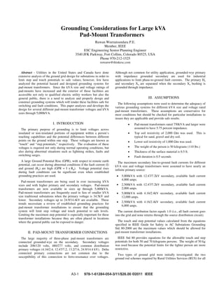
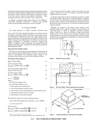
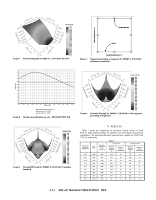
SlideShare a Scribd company logo
Grounding Considerations for Large kVA
Pad-Mount Transformers
Ruwan Weeransundara P.E.
Member, IEEE
ESC Engineering Senior Planning Engineer
3540 JFK Parkway, Fort Collins, Colorado 80525, USA
Phone 970-212-1525
ruwanw@thinkesc.com
Abstract - Utilities in the United States and Canada have done
extensive analysis of the ground grid design for substations in order to
limit step and touch potentials to safe values; however, few have
analyzed the potential hazard and designed grounding systems for
pad-mount transformers. Since the kVA size and voltage ratings of
pad-mounts have increased and the exterior of these facilities are
accessible not only to qualified electric utility workers but also the
general public, there is a need to analyze and properly design and
construct grounding systems which will render these facilities safe for
switching and fault conditions. This paper analyzes and develops the
design for several different pad-mount transformer voltages and kVA
sizes through 5,000kVA.
I. INTRODUCTION
The primary purpose of grounding is to limit voltages across
insulated or non-insulated portions of equipment within a person’s
reaching capabilities and the potential differences between different
points on the ground within one step. These voltages are known as
“touch” and “step potentials,” respectively. The evaluation of these
voltages is required not only during normal operating conditions, but
also during abnormal situations such as lightning strikes, faults and
switching surges.
A large Ground Potential Rise (GPR), with respect to remote earth
potential, can occur during abnormal conditions if the fault current (I)
and ground (Rg) are high (GPR = I x Rg). Voltage potential rises
during fault conditions can be significant even when established
grounding practices are used.
Pad-mount transformers are being used in ever increasing kVA
sizes and with higher primary and secondary voltages. Pad-mount
transformers are now available in sizes up through 5,000kVA.
Pad-mount transformers are frequently used in lieu of smaller kVA
size traditional substations when the primary voltage is 34.5kV and
lower. Secondary voltages up to 24.9/14.4kV are available. These
trends necessitate a review of established grounding practices for
pad-mount transformer installations to ensure that the grounding
system will limit step voltage and touch potential to safe levels.
Limiting the maximum step potential is especially important for these
transformer installations because they are often placed in locations
where the general public can be exposed to danger.
II. PAD-MOUNT TRANSFORMER CONNECTIONS
The large majority of three-phase pad-mount transformers are
connected grounded-wye on the secondary. Secondary voltages
include 208/120 volts, 480/277 volts, and common distribution
primary voltages (4.16/2.4, 12.47/7.2, 13.2/7.6, 24.9/14.4 kV). Delta
connected primary connections are not common due to the
susceptibility of this connection to ferro-resonance over voltages.
Although not common for utility application, grounded-wye primary
with impedance grounded secondary are used for industrial
applications to limit phase-to-ground fault currents. The primary Ho
and secondary Xo are separated when the secondary Xo bushing is
grounded through impedance.
III. ASSUMPTIONS
The following assumptions were used to determine the adequacy of
various grounding systems for different kVA size and voltage rated
pad-mount transformers. These assumptions are conservative for
most conditions but should be checked for particular installations to
insure they are applicable and provide safe results.
Pad-mount transformers rated 750kVA and larger were
assumed to have 5.75 percent impedance.
Top soil resistivity of 2,000 m was used. This is
typical for sand, gravel and dry soil.
Lower soil resistivity of 1,000 m was used.
The weight of the person is 50 kilograms (110 lbs.)
Thickness of the surface material is 0.5 ft.
Fault duration is 0.5 seconds
The maximum secondary line-to-ground fault currents for different
kVA size and voltage transformers were assumed to have nearly an
infinite primary source:
5,000kVA with 12.47/7.2kV secondary, available fault current
4,000 amps.
2,500kVA with 12.47/7.2kV secondary, available fault current
2,000 amps.
5,000kVA with 4.16/2.4kV secondary, available fault current
12,000 amps.
2,500kVA with 4.16/2.4kV secondary, available fault current
6,000 amps.
The current distribution factor equals 1.0 (i.e., all fault current goes
into the grid and none returns through the source distribution circuit).
The touch and step potential values calculated from the equations
specified in IEEE Guide for Safety in AC Substations Grounding
Std. 80-2000 are the maximum values which should be allowed for
pad-mount transformer installations.
IEEE Std 80 provides equations for the allowable touch and step
potentials for both 50 and 70 kilograms persons. The weight of 50 kg
was used because the potential limits for the lighter person are more
restrictive.
Two types of ground grid were initially investigated: the two
ground rod schemes required by Rural Utilities Services (RUS) for all
A3-1 978-1-61284-054-3/11/$26.00 ©2011 IEEE
three-phase underground pad-mounted equipment applications in their
unit UM 48-2 and the Canadian Standards Association Rule 36-302 in
the Electrical Safety Authority, which requires a ground rod on each
of the four corners around the pad-mount transformer. These
grounding schemes are shown in Figures 2 and 3, respectively.
In addition, a suggested sample design (Figure 4) for a 5000kVA,
34.5/4.16kV pad-mount transformer is included. The potential
contour for the grounding arrangement is shown in Graph 4.
IV. CALCULATIONS
The ground potential rise (GPR), maximum allowable touch
( and step ( potential calculations were performed using
the equations specified in IEEE Std 80-2000. The grounding analysis
was performed for different kVA sizes and voltage ratings of pad-
mount transformers with both the RUS and Canadian Standards. The
EDSA Advanced Ground Mat Program V4.70.00 was used to perform
sample calculations on pad-mount transformers, ranging from
500kVA to 5000kVA. These calculations were compared with the
maximum allowable values calculated from the equations specified in
IEEE Standard 80-2000.
Step and Touch Voltage Criteria
The safety of a person depends on preventing the critical amount of
shock energy from being absorbed before the fault is cleared and the
system is de-energized. The maximum driving voltage of any
accidental circuit should not exceed the limits defined as follows.
The limit for Step Voltage is: 1
(1)
For body weight of 50kg:
1 (2)
Similarly, the touch voltage limit is:
(3)
For body weight of 50kg:
(4)
(5)
Where:
Estep-The step voltage in volts
Etouch-The touch voltage in volts
Cs -The surface layer de-rating factor
S- The surface material resistivity in m
- The resistivity of the earth beneath the surface material in m
ts -The duration of shock current in seconds
hs -The thickness of the surface material
The following values were used for grounding analysis:
Cs=1.0 (No earth beneath surface material), = S = 2000 m
ts = 0.5 sec, hs=0-.5 ft.
From (2) & (4)
= 2312.6V (6)
= 656.2V (7)
1
IEEE – Guide For Safety in AC Substation Grounding, IEEE – Std. 80-2000, pp- 23-37
The actual step and touch voltages, metal to touch and step to step
voltages, should be less than the respective maximum allowable
voltage limits to ensure safety.
It should be noted that the above calculations assume 0.5 seconds
fault duration. With a square root of ts in the denominator of equations
(6) and (7) above, the allowable step and touch voltages will both be
decreased with an increase in fault clearing time. Increasing the fault
duration time from 0.5 seconds to 2.0 seconds will reduce the above
values by one-half.
Although not common in the electric utility industry, some
industrial electrical users separate the primary H0 and secondary X0
connection points to obtain an impedance grounded secondary
system. When this is done, the maximum voltages during fault
conditions will not be limited by the secondary windings and the
touch potentials as well as the step potentials will exceed those which
would occur for a grounded wye to grounded wye connection with the
H0 and X0 points bonded.
Figure 1 Human Tolerances Model
Figure 2 RUS Std UM48-2, 3-Phase Pad-Mounted Grounding
Figure 3 Canadian Standard for Pad-Mounted Grounding
A3-2 978-1-61284-054-3/11/$26.00 ©2011 IEEE
Graph 1 Potential 3D graph for 5000kVA, 34.5/4.16kV RUS Std
Graph 2 Absolute potential along an axis – 34.5/4.16kV RUS Std
Graph 3 Potential 3D Graph for 5000kVA, 34.5/4.16kV Canadian
Standard
Figure 4 Suggested grounding arrangement for 5000kVA 34.5/4.16kV
pad-mount transformer
Graph 4 Potential 3D graph for 5000kVA, 34.5/4.16kV with suggested
grounding arrangement
V. RESULTS
Table 1 shows the comparison of maximum surface voltage on both
RUS Std and Canadian Standard for different sizes and voltages of pad mount
transformers. The maximum allowable touch and step voltages are 656.2V and
2312.6V respectively.
Table 1
Transformer
Secondary
Voltage (kV)
Size
(KVA)
Maximum
Line-Ground
Fault
Current (A)
Maximum
Surface
Potential
(V)
Meets the
Safety
Requirement
Maximum
Surface
Potential
(V)
Meets the
Safety
Requirement
12.47 5000 4000 1655 707
12.47 2500 2000 875 338
12.47 1500 1250 601 205
4.16 5000 12000 4551 1491
4.16 2500 6000 1848 911
4.16 1500 3500 1454 515
4.16 1000 2250 933 404
4.16 750 2000 875 338
4.16 500 1000
A3-3 978-1-61284-054-3/11/$26.00 ©2011 IEEE
VI. CONCLUSIONS AND RECOMMENDATIONS
With the RUS two ground rod standard, the maximum surface
potential as well as the maximum 1.0 meter gradient potential can be
exceeded for large kVA size pad-mount transformers with 4.16/2.4kV
and higher secondary voltages. The Canadian Electrical Safety Code
which requires four grounding rods, one on each corner, provides
better results but still fails for some larger kVA sizes and higher
secondary voltages. A detailed engineered grounding design should
be prepared by a qualified person for pad-mount transformer
installations exceeding 750kVA when the secondary voltage is
4.16/2.4kV or higher or if the fault clearing time exceeds 0.5 seconds.
Since the allowable step and touch potentials decrease with an
increase in the shock current duration time, it is important to consider
the maximum fault clearing time when designing ground systems for
pad-mount transformers. A detailed grounding design requires
knowledge or measurement of the soil resistance at the pad-mount
transformer location plus information regarding any possible
deviation from the assumptions used in this paper. In addition, a
detailed grounding design should be done for all grounded wye to
impedance grounded secondary when the H0 and X0 are not connected
to provide an impedance grounded secondary.
VII. REFERENCES
[1] IEEE for Safety in AC Substation Grounding IEEE
Standard 80-2000.
[2] Canadian Electrical Safety Code, 2009, by Electrical Safety
Authority.
[3] RUS Standard 1728F-806, June 2000, Specifications and
Drawings for Underground Electric Distribution.
[4] IEEE Recommended Practice for Grounding of Industrial &
Commercial Power Systems, ANSI/IEEE Std 142-1982
VIII. BIOGRAPHY
Ruwan Weeransundara received a BSEE from the University of
Peradeniya Sri Lanka in 1987 and a MSEE from the University of
Windsor, Ontario Canada in 2004. From 1987 to 2000, he worked as a
Power System Engineer for Ceylon Electricity Board in Sri Lanka
with an emphasis on Power Distribution, Protection of Transmission
and Generating Stations and Substation Design. In 2000, he joined
Siemens Canada as a Field Service Engineer. In 2004, he joined
Schneider Electric Canada as Senior Power System Engineer and in
2009, he joined ESC engineering, Inc. as a Senior Planning Engineer.
He is a member of IEEE and a Registered Professional Engineer in
the Province of Ontario Canada.
A3-4 978-1-61284-054-3/11/$26.00 ©2011 IEEE

More Related Content

What's hot

Hv module 3 Impulse voltage generation
Hv module 3 Impulse voltage generationHv module 3 Impulse voltage generation
Hv module 3 Impulse voltage generation
Asha Anu Kurian
 
Flexible Ac Transmission Systems 2Mark Materials and Question Bank
Flexible Ac Transmission Systems 2Mark Materials and Question BankFlexible Ac Transmission Systems 2Mark Materials and Question Bank
Flexible Ac Transmission Systems 2Mark Materials and Question Bank
Santhosh Kumar
 
Electrical power system(capacitance of transmission line)
Electrical power system(capacitance of transmission line)Electrical power system(capacitance of transmission line)
Electrical power system(capacitance of transmission line)
Arshad Hussain
 
Underground cables vs overhead lines
Underground cables vs overhead linesUnderground cables vs overhead lines
Underground cables vs overhead lines
ସୁର୍ଯ଼ ପ୍ରତାପ ଭଞ୍ଜ
 
High voltage engineering
High voltage engineeringHigh voltage engineering
High voltage engineering
Hari Kumar
 
Hvdc technology
Hvdc technologyHvdc technology
Hvdc technology
BhargavDNVK
 
Puntas terminales
Puntas terminalesPuntas terminales
Puntas terminales
GEOVANNY PILLAJO
 
Generator Protection Relay Setting Calculations
Generator Protection Relay Setting CalculationsGenerator Protection Relay Setting Calculations
Generator Protection Relay Setting Calculations
Power System Operation
 
Power cables
Power cablesPower cables
Power cables
ahmdfurkan
 
Chapter 2 transmission line parameters
Chapter 2  transmission line parametersChapter 2  transmission line parameters
Chapter 2 transmission line parameters
firaoltemesgen1
 
Substation overview
Substation overviewSubstation overview
Substation overview
BHAGWAN PRASAD
 
Sheath bonding method for underground cables
Sheath bonding method for underground cablesSheath bonding method for underground cables
Sheath bonding method for underground cables
Ahmed Adel Gouda, PMP certified
 
Insulators
InsulatorsInsulators
Insulators
Ravi teja Damerla
 
Inductance and capacitance
Inductance and capacitanceInductance and capacitance
Inductance and capacitance
GHSKassKoronaMardan
 
400 kv nelmangala
400 kv nelmangala400 kv nelmangala
400 kv nelmangala
Mayur Dhanaji Rane
 
Ehv substation
Ehv substationEhv substation
Ehv substation
Demsew Mitiku
 
Power cable - Voltage drop
Power cable - Voltage dropPower cable - Voltage drop
Power cable - Voltage drop
Leonardo ENERGY
 
Introduction to reactive power control in electrical power
Introduction to reactive power control in electrical powerIntroduction to reactive power control in electrical power
Introduction to reactive power control in electrical power
Dr.Raja R
 
A training report on 132 KV GSS, BHADOTI, sawai madhopur
A training report on 132 KV GSS, BHADOTI, sawai madhopurA training report on 132 KV GSS, BHADOTI, sawai madhopur
A training report on 132 KV GSS, BHADOTI, sawai madhopur
dilkhush009
 
Power cables
Power cablesPower cables
Power cables
college
 

What's hot (20)

Hv module 3 Impulse voltage generation
Hv module 3 Impulse voltage generationHv module 3 Impulse voltage generation
Hv module 3 Impulse voltage generation
 
Flexible Ac Transmission Systems 2Mark Materials and Question Bank
Flexible Ac Transmission Systems 2Mark Materials and Question BankFlexible Ac Transmission Systems 2Mark Materials and Question Bank
Flexible Ac Transmission Systems 2Mark Materials and Question Bank
 
Electrical power system(capacitance of transmission line)
Electrical power system(capacitance of transmission line)Electrical power system(capacitance of transmission line)
Electrical power system(capacitance of transmission line)
 
Underground cables vs overhead lines
Underground cables vs overhead linesUnderground cables vs overhead lines
Underground cables vs overhead lines
 
High voltage engineering
High voltage engineeringHigh voltage engineering
High voltage engineering
 
Hvdc technology
Hvdc technologyHvdc technology
Hvdc technology
 
Puntas terminales
Puntas terminalesPuntas terminales
Puntas terminales
 
Generator Protection Relay Setting Calculations
Generator Protection Relay Setting CalculationsGenerator Protection Relay Setting Calculations
Generator Protection Relay Setting Calculations
 
Power cables
Power cablesPower cables
Power cables
 
Chapter 2 transmission line parameters
Chapter 2  transmission line parametersChapter 2  transmission line parameters
Chapter 2 transmission line parameters
 
Substation overview
Substation overviewSubstation overview
Substation overview
 
Sheath bonding method for underground cables
Sheath bonding method for underground cablesSheath bonding method for underground cables
Sheath bonding method for underground cables
 
Insulators
InsulatorsInsulators
Insulators
 
Inductance and capacitance
Inductance and capacitanceInductance and capacitance
Inductance and capacitance
 
400 kv nelmangala
400 kv nelmangala400 kv nelmangala
400 kv nelmangala
 
Ehv substation
Ehv substationEhv substation
Ehv substation
 
Power cable - Voltage drop
Power cable - Voltage dropPower cable - Voltage drop
Power cable - Voltage drop
 
Introduction to reactive power control in electrical power
Introduction to reactive power control in electrical powerIntroduction to reactive power control in electrical power
Introduction to reactive power control in electrical power
 
A training report on 132 KV GSS, BHADOTI, sawai madhopur
A training report on 132 KV GSS, BHADOTI, sawai madhopurA training report on 132 KV GSS, BHADOTI, sawai madhopur
A training report on 132 KV GSS, BHADOTI, sawai madhopur
 
Power cables
Power cablesPower cables
Power cables
 

Similar to Grounding pad mounted transformers

11.[21 28]voltage stability improvement using the 21st century power transformer
11.[21 28]voltage stability improvement using the 21st century power transformer11.[21 28]voltage stability improvement using the 21st century power transformer
11.[21 28]voltage stability improvement using the 21st century power transformer
Alexander Decker
 
Review of Reduction of Leakage Current in Cascaded Multilevel Inverter
Review of Reduction of Leakage Current in Cascaded Multilevel InverterReview of Reduction of Leakage Current in Cascaded Multilevel Inverter
Review of Reduction of Leakage Current in Cascaded Multilevel Inverter
IJRST Journal
 
Cascade Protection with Transient Voltage copy
Cascade Protection with Transient Voltage copyCascade Protection with Transient Voltage copy
Cascade Protection with Transient Voltage copy
Jesus A Borjas P.E., California
 
Assessment of Electric Field Distribution Inside 500/220 kV Open Distribution...
Assessment of Electric Field Distribution Inside 500/220 kV Open Distribution...Assessment of Electric Field Distribution Inside 500/220 kV Open Distribution...
Assessment of Electric Field Distribution Inside 500/220 kV Open Distribution...
IJAPEJOURNAL
 
Techno economic study of series current limiting reactor and its impact in th...
Techno economic study of series current limiting reactor and its impact in th...Techno economic study of series current limiting reactor and its impact in th...
Techno economic study of series current limiting reactor and its impact in th...
Alexander Decker
 
Training at 132 kv substation
Training at 132 kv substation Training at 132 kv substation
Training at 132 kv substation
Tejveer Choudhary
 
Technical presentation on modern earthing
Technical presentation on modern earthingTechnical presentation on modern earthing
Technical presentation on modern earthing
Pankaj Chakraborty
 
IRJET - A Zero Voltage Switching Pulse Width Modulated Multilevel Buck Converter
IRJET - A Zero Voltage Switching Pulse Width Modulated Multilevel Buck ConverterIRJET - A Zero Voltage Switching Pulse Width Modulated Multilevel Buck Converter
IRJET - A Zero Voltage Switching Pulse Width Modulated Multilevel Buck Converter
IRJET Journal
 
Wireless Power Transfer Project
Wireless Power Transfer  ProjectWireless Power Transfer  Project
Wireless Power Transfer Project
sagnikchoudhury
 
WIRELESS POWER TRANSMISSION Project
WIRELESS POWER TRANSMISSION ProjectWIRELESS POWER TRANSMISSION Project
WIRELESS POWER TRANSMISSION Project
sagnikchoudhury
 
Introduction to mv switchgear
Introduction to mv switchgearIntroduction to mv switchgear
Introduction to mv switchgear
Modal Holong Education
 
kamal project ppt
kamal project pptkamal project ppt
kamal project ppt
kamaldeep singh
 
International Journal of Computational Engineering Research (IJCER)
International Journal of Computational Engineering Research (IJCER)International Journal of Computational Engineering Research (IJCER)
International Journal of Computational Engineering Research (IJCER)
ijceronline
 
Analysis of example_capacitor_bank_switching_solution_and_recommendations_for...
Analysis of example_capacitor_bank_switching_solution_and_recommendations_for...Analysis of example_capacitor_bank_switching_solution_and_recommendations_for...
Analysis of example_capacitor_bank_switching_solution_and_recommendations_for...
f95346
 
132 33kv substation documentation
132 33kv substation documentation132 33kv substation documentation
132 33kv substation documentation
Rajashekar Gurrala
 
Your electrical safety specilist for all equipments Powered AC and DC
Your electrical safety specilist for all equipments   Powered AC and DCYour electrical safety specilist for all equipments   Powered AC and DC
Your electrical safety specilist for all equipments Powered AC and DC
Mahesh Chandra Manav
 
High efficiency three phase nine level diode clamped multilevel inverter
High efficiency three phase nine level diode clamped multilevel inverterHigh efficiency three phase nine level diode clamped multilevel inverter
High efficiency three phase nine level diode clamped multilevel inverter
International Journal of Science and Research (IJSR)
 
2
22
Investigation of Electric Field Distribution Inside 500/220 kV Transformation...
Investigation of Electric Field Distribution Inside 500/220 kV Transformation...Investigation of Electric Field Distribution Inside 500/220 kV Transformation...
Investigation of Electric Field Distribution Inside 500/220 kV Transformation...
IJAPEJOURNAL
 
Analsis of very fast transient over voltages in gas insulated substations
Analsis of very fast transient over voltages in gas insulated substationsAnalsis of very fast transient over voltages in gas insulated substations
Analsis of very fast transient over voltages in gas insulated substations
eSAT Journals
 

Similar to Grounding pad mounted transformers (20)

11.[21 28]voltage stability improvement using the 21st century power transformer
11.[21 28]voltage stability improvement using the 21st century power transformer11.[21 28]voltage stability improvement using the 21st century power transformer
11.[21 28]voltage stability improvement using the 21st century power transformer
 
Review of Reduction of Leakage Current in Cascaded Multilevel Inverter
Review of Reduction of Leakage Current in Cascaded Multilevel InverterReview of Reduction of Leakage Current in Cascaded Multilevel Inverter
Review of Reduction of Leakage Current in Cascaded Multilevel Inverter
 
Cascade Protection with Transient Voltage copy
Cascade Protection with Transient Voltage copyCascade Protection with Transient Voltage copy
Cascade Protection with Transient Voltage copy
 
Assessment of Electric Field Distribution Inside 500/220 kV Open Distribution...
Assessment of Electric Field Distribution Inside 500/220 kV Open Distribution...Assessment of Electric Field Distribution Inside 500/220 kV Open Distribution...
Assessment of Electric Field Distribution Inside 500/220 kV Open Distribution...
 
Techno economic study of series current limiting reactor and its impact in th...
Techno economic study of series current limiting reactor and its impact in th...Techno economic study of series current limiting reactor and its impact in th...
Techno economic study of series current limiting reactor and its impact in th...
 
Training at 132 kv substation
Training at 132 kv substation Training at 132 kv substation
Training at 132 kv substation
 
Technical presentation on modern earthing
Technical presentation on modern earthingTechnical presentation on modern earthing
Technical presentation on modern earthing
 
IRJET - A Zero Voltage Switching Pulse Width Modulated Multilevel Buck Converter
IRJET - A Zero Voltage Switching Pulse Width Modulated Multilevel Buck ConverterIRJET - A Zero Voltage Switching Pulse Width Modulated Multilevel Buck Converter
IRJET - A Zero Voltage Switching Pulse Width Modulated Multilevel Buck Converter
 
Wireless Power Transfer Project
Wireless Power Transfer  ProjectWireless Power Transfer  Project
Wireless Power Transfer Project
 
WIRELESS POWER TRANSMISSION Project
WIRELESS POWER TRANSMISSION ProjectWIRELESS POWER TRANSMISSION Project
WIRELESS POWER TRANSMISSION Project
 
Introduction to mv switchgear
Introduction to mv switchgearIntroduction to mv switchgear
Introduction to mv switchgear
 
kamal project ppt
kamal project pptkamal project ppt
kamal project ppt
 
International Journal of Computational Engineering Research (IJCER)
International Journal of Computational Engineering Research (IJCER)International Journal of Computational Engineering Research (IJCER)
International Journal of Computational Engineering Research (IJCER)
 
Analysis of example_capacitor_bank_switching_solution_and_recommendations_for...
Analysis of example_capacitor_bank_switching_solution_and_recommendations_for...Analysis of example_capacitor_bank_switching_solution_and_recommendations_for...
Analysis of example_capacitor_bank_switching_solution_and_recommendations_for...
 
132 33kv substation documentation
132 33kv substation documentation132 33kv substation documentation
132 33kv substation documentation
 
Your electrical safety specilist for all equipments Powered AC and DC
Your electrical safety specilist for all equipments   Powered AC and DCYour electrical safety specilist for all equipments   Powered AC and DC
Your electrical safety specilist for all equipments Powered AC and DC
 
High efficiency three phase nine level diode clamped multilevel inverter
High efficiency three phase nine level diode clamped multilevel inverterHigh efficiency three phase nine level diode clamped multilevel inverter
High efficiency three phase nine level diode clamped multilevel inverter
 
2
22
2
 
Investigation of Electric Field Distribution Inside 500/220 kV Transformation...
Investigation of Electric Field Distribution Inside 500/220 kV Transformation...Investigation of Electric Field Distribution Inside 500/220 kV Transformation...
Investigation of Electric Field Distribution Inside 500/220 kV Transformation...
 
Analsis of very fast transient over voltages in gas insulated substations
Analsis of very fast transient over voltages in gas insulated substationsAnalsis of very fast transient over voltages in gas insulated substations
Analsis of very fast transient over voltages in gas insulated substations
 

Recently uploaded

Exception Handling notes in java exception
Exception Handling notes in java exceptionException Handling notes in java exception
Exception Handling notes in java exception
Ratnakar Mikkili
 
bank management system in java and mysql report1.pdf
bank management system in java and mysql report1.pdfbank management system in java and mysql report1.pdf
bank management system in java and mysql report1.pdf
Divyam548318
 
DfMAy 2024 - key insights and contributions
DfMAy 2024 - key insights and contributionsDfMAy 2024 - key insights and contributions
DfMAy 2024 - key insights and contributions
gestioneergodomus
 
Series of visio cisco devices Cisco_Icons.ppt
Series of visio cisco devices Cisco_Icons.pptSeries of visio cisco devices Cisco_Icons.ppt
Series of visio cisco devices Cisco_Icons.ppt
PauloRodrigues104553
 
digital fundamental by Thomas L.floydl.pdf
digital fundamental by Thomas L.floydl.pdfdigital fundamental by Thomas L.floydl.pdf
digital fundamental by Thomas L.floydl.pdf
drwaing
 
[JPP-1] - (JEE 3.0) - Kinematics 1D - 14th May..pdf
[JPP-1] - (JEE 3.0) - Kinematics 1D - 14th May..pdf[JPP-1] - (JEE 3.0) - Kinematics 1D - 14th May..pdf
[JPP-1] - (JEE 3.0) - Kinematics 1D - 14th May..pdf
awadeshbabu
 
DEEP LEARNING FOR SMART GRID INTRUSION DETECTION: A HYBRID CNN-LSTM-BASED MODEL
DEEP LEARNING FOR SMART GRID INTRUSION DETECTION: A HYBRID CNN-LSTM-BASED MODELDEEP LEARNING FOR SMART GRID INTRUSION DETECTION: A HYBRID CNN-LSTM-BASED MODEL
DEEP LEARNING FOR SMART GRID INTRUSION DETECTION: A HYBRID CNN-LSTM-BASED MODEL
gerogepatton
 
CHINA’S GEO-ECONOMIC OUTREACH IN CENTRAL ASIAN COUNTRIES AND FUTURE PROSPECT
CHINA’S GEO-ECONOMIC OUTREACH IN CENTRAL ASIAN COUNTRIES AND FUTURE PROSPECTCHINA’S GEO-ECONOMIC OUTREACH IN CENTRAL ASIAN COUNTRIES AND FUTURE PROSPECT
CHINA’S GEO-ECONOMIC OUTREACH IN CENTRAL ASIAN COUNTRIES AND FUTURE PROSPECT
jpsjournal1
 
Presentation of IEEE Slovenia CIS (Computational Intelligence Society) Chapte...
Presentation of IEEE Slovenia CIS (Computational Intelligence Society) Chapte...Presentation of IEEE Slovenia CIS (Computational Intelligence Society) Chapte...
Presentation of IEEE Slovenia CIS (Computational Intelligence Society) Chapte...
University of Maribor
 
sieving analysis and results interpretation
sieving analysis and results interpretationsieving analysis and results interpretation
sieving analysis and results interpretation
ssuser36d3051
 
Swimming pool mechanical components design.pptx
Swimming pool  mechanical components design.pptxSwimming pool  mechanical components design.pptx
Swimming pool mechanical components design.pptx
yokeleetan1
 
Properties Railway Sleepers and Test.pptx
Properties Railway Sleepers and Test.pptxProperties Railway Sleepers and Test.pptx
Properties Railway Sleepers and Test.pptx
MDSABBIROJJAMANPAYEL
 
Wearable antenna for antenna applications
Wearable antenna for antenna applicationsWearable antenna for antenna applications
Wearable antenna for antenna applications
Madhumitha Jayaram
 
Heat Resistant Concrete Presentation ppt
Heat Resistant Concrete Presentation pptHeat Resistant Concrete Presentation ppt
Heat Resistant Concrete Presentation ppt
mamunhossenbd75
 
KuberTENes Birthday Bash Guadalajara - K8sGPT first impressions
KuberTENes Birthday Bash Guadalajara - K8sGPT first impressionsKuberTENes Birthday Bash Guadalajara - K8sGPT first impressions
KuberTENes Birthday Bash Guadalajara - K8sGPT first impressions
Victor Morales
 
Harnessing WebAssembly for Real-time Stateless Streaming Pipelines
Harnessing WebAssembly for Real-time Stateless Streaming PipelinesHarnessing WebAssembly for Real-time Stateless Streaming Pipelines
Harnessing WebAssembly for Real-time Stateless Streaming Pipelines
Christina Lin
 
ACRP 4-09 Risk Assessment Method to Support Modification of Airfield Separat...
ACRP 4-09 Risk Assessment Method to Support Modification of Airfield Separat...ACRP 4-09 Risk Assessment Method to Support Modification of Airfield Separat...
ACRP 4-09 Risk Assessment Method to Support Modification of Airfield Separat...
Mukeshwaran Balu
 
Iron and Steel Technology Roadmap - Towards more sustainable steelmaking.pdf
Iron and Steel Technology Roadmap - Towards more sustainable steelmaking.pdfIron and Steel Technology Roadmap - Towards more sustainable steelmaking.pdf
Iron and Steel Technology Roadmap - Towards more sustainable steelmaking.pdf
RadiNasr
 
Question paper of renewable energy sources
Question paper of renewable energy sourcesQuestion paper of renewable energy sources
Question paper of renewable energy sources
mahammadsalmanmech
 
Embedded machine learning-based road conditions and driving behavior monitoring
Embedded machine learning-based road conditions and driving behavior monitoringEmbedded machine learning-based road conditions and driving behavior monitoring
Embedded machine learning-based road conditions and driving behavior monitoring
IJECEIAES
 

Recently uploaded (20)

Exception Handling notes in java exception
Exception Handling notes in java exceptionException Handling notes in java exception
Exception Handling notes in java exception
 
bank management system in java and mysql report1.pdf
bank management system in java and mysql report1.pdfbank management system in java and mysql report1.pdf
bank management system in java and mysql report1.pdf
 
DfMAy 2024 - key insights and contributions
DfMAy 2024 - key insights and contributionsDfMAy 2024 - key insights and contributions
DfMAy 2024 - key insights and contributions
 
Series of visio cisco devices Cisco_Icons.ppt
Series of visio cisco devices Cisco_Icons.pptSeries of visio cisco devices Cisco_Icons.ppt
Series of visio cisco devices Cisco_Icons.ppt
 
digital fundamental by Thomas L.floydl.pdf
digital fundamental by Thomas L.floydl.pdfdigital fundamental by Thomas L.floydl.pdf
digital fundamental by Thomas L.floydl.pdf
 
[JPP-1] - (JEE 3.0) - Kinematics 1D - 14th May..pdf
[JPP-1] - (JEE 3.0) - Kinematics 1D - 14th May..pdf[JPP-1] - (JEE 3.0) - Kinematics 1D - 14th May..pdf
[JPP-1] - (JEE 3.0) - Kinematics 1D - 14th May..pdf
 
DEEP LEARNING FOR SMART GRID INTRUSION DETECTION: A HYBRID CNN-LSTM-BASED MODEL
DEEP LEARNING FOR SMART GRID INTRUSION DETECTION: A HYBRID CNN-LSTM-BASED MODELDEEP LEARNING FOR SMART GRID INTRUSION DETECTION: A HYBRID CNN-LSTM-BASED MODEL
DEEP LEARNING FOR SMART GRID INTRUSION DETECTION: A HYBRID CNN-LSTM-BASED MODEL
 
CHINA’S GEO-ECONOMIC OUTREACH IN CENTRAL ASIAN COUNTRIES AND FUTURE PROSPECT
CHINA’S GEO-ECONOMIC OUTREACH IN CENTRAL ASIAN COUNTRIES AND FUTURE PROSPECTCHINA’S GEO-ECONOMIC OUTREACH IN CENTRAL ASIAN COUNTRIES AND FUTURE PROSPECT
CHINA’S GEO-ECONOMIC OUTREACH IN CENTRAL ASIAN COUNTRIES AND FUTURE PROSPECT
 
Presentation of IEEE Slovenia CIS (Computational Intelligence Society) Chapte...
Presentation of IEEE Slovenia CIS (Computational Intelligence Society) Chapte...Presentation of IEEE Slovenia CIS (Computational Intelligence Society) Chapte...
Presentation of IEEE Slovenia CIS (Computational Intelligence Society) Chapte...
 
sieving analysis and results interpretation
sieving analysis and results interpretationsieving analysis and results interpretation
sieving analysis and results interpretation
 
Swimming pool mechanical components design.pptx
Swimming pool  mechanical components design.pptxSwimming pool  mechanical components design.pptx
Swimming pool mechanical components design.pptx
 
Properties Railway Sleepers and Test.pptx
Properties Railway Sleepers and Test.pptxProperties Railway Sleepers and Test.pptx
Properties Railway Sleepers and Test.pptx
 
Wearable antenna for antenna applications
Wearable antenna for antenna applicationsWearable antenna for antenna applications
Wearable antenna for antenna applications
 
Heat Resistant Concrete Presentation ppt
Heat Resistant Concrete Presentation pptHeat Resistant Concrete Presentation ppt
Heat Resistant Concrete Presentation ppt
 
KuberTENes Birthday Bash Guadalajara - K8sGPT first impressions
KuberTENes Birthday Bash Guadalajara - K8sGPT first impressionsKuberTENes Birthday Bash Guadalajara - K8sGPT first impressions
KuberTENes Birthday Bash Guadalajara - K8sGPT first impressions
 
Harnessing WebAssembly for Real-time Stateless Streaming Pipelines
Harnessing WebAssembly for Real-time Stateless Streaming PipelinesHarnessing WebAssembly for Real-time Stateless Streaming Pipelines
Harnessing WebAssembly for Real-time Stateless Streaming Pipelines
 
ACRP 4-09 Risk Assessment Method to Support Modification of Airfield Separat...
ACRP 4-09 Risk Assessment Method to Support Modification of Airfield Separat...ACRP 4-09 Risk Assessment Method to Support Modification of Airfield Separat...
ACRP 4-09 Risk Assessment Method to Support Modification of Airfield Separat...
 
Iron and Steel Technology Roadmap - Towards more sustainable steelmaking.pdf
Iron and Steel Technology Roadmap - Towards more sustainable steelmaking.pdfIron and Steel Technology Roadmap - Towards more sustainable steelmaking.pdf
Iron and Steel Technology Roadmap - Towards more sustainable steelmaking.pdf
 
Question paper of renewable energy sources
Question paper of renewable energy sourcesQuestion paper of renewable energy sources
Question paper of renewable energy sources
 
Embedded machine learning-based road conditions and driving behavior monitoring
Embedded machine learning-based road conditions and driving behavior monitoringEmbedded machine learning-based road conditions and driving behavior monitoring
Embedded machine learning-based road conditions and driving behavior monitoring
 

Grounding pad mounted transformers

  • 1. Grounding Considerations for Large kVA Pad-Mount Transformers Ruwan Weeransundara P.E. Member, IEEE ESC Engineering Senior Planning Engineer 3540 JFK Parkway, Fort Collins, Colorado 80525, USA Phone 970-212-1525 ruwanw@thinkesc.com Abstract - Utilities in the United States and Canada have done extensive analysis of the ground grid design for substations in order to limit step and touch potentials to safe values; however, few have analyzed the potential hazard and designed grounding systems for pad-mount transformers. Since the kVA size and voltage ratings of pad-mounts have increased and the exterior of these facilities are accessible not only to qualified electric utility workers but also the general public, there is a need to analyze and properly design and construct grounding systems which will render these facilities safe for switching and fault conditions. This paper analyzes and develops the design for several different pad-mount transformer voltages and kVA sizes through 5,000kVA. I. INTRODUCTION The primary purpose of grounding is to limit voltages across insulated or non-insulated portions of equipment within a person’s reaching capabilities and the potential differences between different points on the ground within one step. These voltages are known as “touch” and “step potentials,” respectively. The evaluation of these voltages is required not only during normal operating conditions, but also during abnormal situations such as lightning strikes, faults and switching surges. A large Ground Potential Rise (GPR), with respect to remote earth potential, can occur during abnormal conditions if the fault current (I) and ground (Rg) are high (GPR = I x Rg). Voltage potential rises during fault conditions can be significant even when established grounding practices are used. Pad-mount transformers are being used in ever increasing kVA sizes and with higher primary and secondary voltages. Pad-mount transformers are now available in sizes up through 5,000kVA. Pad-mount transformers are frequently used in lieu of smaller kVA size traditional substations when the primary voltage is 34.5kV and lower. Secondary voltages up to 24.9/14.4kV are available. These trends necessitate a review of established grounding practices for pad-mount transformer installations to ensure that the grounding system will limit step voltage and touch potential to safe levels. Limiting the maximum step potential is especially important for these transformer installations because they are often placed in locations where the general public can be exposed to danger. II. PAD-MOUNT TRANSFORMER CONNECTIONS The large majority of three-phase pad-mount transformers are connected grounded-wye on the secondary. Secondary voltages include 208/120 volts, 480/277 volts, and common distribution primary voltages (4.16/2.4, 12.47/7.2, 13.2/7.6, 24.9/14.4 kV). Delta connected primary connections are not common due to the susceptibility of this connection to ferro-resonance over voltages. Although not common for utility application, grounded-wye primary with impedance grounded secondary are used for industrial applications to limit phase-to-ground fault currents. The primary Ho and secondary Xo are separated when the secondary Xo bushing is grounded through impedance. III. ASSUMPTIONS The following assumptions were used to determine the adequacy of various grounding systems for different kVA size and voltage rated pad-mount transformers. These assumptions are conservative for most conditions but should be checked for particular installations to insure they are applicable and provide safe results. Pad-mount transformers rated 750kVA and larger were assumed to have 5.75 percent impedance. Top soil resistivity of 2,000 m was used. This is typical for sand, gravel and dry soil. Lower soil resistivity of 1,000 m was used. The weight of the person is 50 kilograms (110 lbs.) Thickness of the surface material is 0.5 ft. Fault duration is 0.5 seconds The maximum secondary line-to-ground fault currents for different kVA size and voltage transformers were assumed to have nearly an infinite primary source: 5,000kVA with 12.47/7.2kV secondary, available fault current 4,000 amps. 2,500kVA with 12.47/7.2kV secondary, available fault current 2,000 amps. 5,000kVA with 4.16/2.4kV secondary, available fault current 12,000 amps. 2,500kVA with 4.16/2.4kV secondary, available fault current 6,000 amps. The current distribution factor equals 1.0 (i.e., all fault current goes into the grid and none returns through the source distribution circuit). The touch and step potential values calculated from the equations specified in IEEE Guide for Safety in AC Substations Grounding Std. 80-2000 are the maximum values which should be allowed for pad-mount transformer installations. IEEE Std 80 provides equations for the allowable touch and step potentials for both 50 and 70 kilograms persons. The weight of 50 kg was used because the potential limits for the lighter person are more restrictive. Two types of ground grid were initially investigated: the two ground rod schemes required by Rural Utilities Services (RUS) for all A3-1 978-1-61284-054-3/11/$26.00 ©2011 IEEE
  • 2. three-phase underground pad-mounted equipment applications in their unit UM 48-2 and the Canadian Standards Association Rule 36-302 in the Electrical Safety Authority, which requires a ground rod on each of the four corners around the pad-mount transformer. These grounding schemes are shown in Figures 2 and 3, respectively. In addition, a suggested sample design (Figure 4) for a 5000kVA, 34.5/4.16kV pad-mount transformer is included. The potential contour for the grounding arrangement is shown in Graph 4. IV. CALCULATIONS The ground potential rise (GPR), maximum allowable touch ( and step ( potential calculations were performed using the equations specified in IEEE Std 80-2000. The grounding analysis was performed for different kVA sizes and voltage ratings of pad- mount transformers with both the RUS and Canadian Standards. The EDSA Advanced Ground Mat Program V4.70.00 was used to perform sample calculations on pad-mount transformers, ranging from 500kVA to 5000kVA. These calculations were compared with the maximum allowable values calculated from the equations specified in IEEE Standard 80-2000. Step and Touch Voltage Criteria The safety of a person depends on preventing the critical amount of shock energy from being absorbed before the fault is cleared and the system is de-energized. The maximum driving voltage of any accidental circuit should not exceed the limits defined as follows. The limit for Step Voltage is: 1 (1) For body weight of 50kg: 1 (2) Similarly, the touch voltage limit is: (3) For body weight of 50kg: (4) (5) Where: Estep-The step voltage in volts Etouch-The touch voltage in volts Cs -The surface layer de-rating factor S- The surface material resistivity in m - The resistivity of the earth beneath the surface material in m ts -The duration of shock current in seconds hs -The thickness of the surface material The following values were used for grounding analysis: Cs=1.0 (No earth beneath surface material), = S = 2000 m ts = 0.5 sec, hs=0-.5 ft. From (2) & (4) = 2312.6V (6) = 656.2V (7) 1 IEEE – Guide For Safety in AC Substation Grounding, IEEE – Std. 80-2000, pp- 23-37 The actual step and touch voltages, metal to touch and step to step voltages, should be less than the respective maximum allowable voltage limits to ensure safety. It should be noted that the above calculations assume 0.5 seconds fault duration. With a square root of ts in the denominator of equations (6) and (7) above, the allowable step and touch voltages will both be decreased with an increase in fault clearing time. Increasing the fault duration time from 0.5 seconds to 2.0 seconds will reduce the above values by one-half. Although not common in the electric utility industry, some industrial electrical users separate the primary H0 and secondary X0 connection points to obtain an impedance grounded secondary system. When this is done, the maximum voltages during fault conditions will not be limited by the secondary windings and the touch potentials as well as the step potentials will exceed those which would occur for a grounded wye to grounded wye connection with the H0 and X0 points bonded. Figure 1 Human Tolerances Model Figure 2 RUS Std UM48-2, 3-Phase Pad-Mounted Grounding Figure 3 Canadian Standard for Pad-Mounted Grounding A3-2 978-1-61284-054-3/11/$26.00 ©2011 IEEE
  • 3. Graph 1 Potential 3D graph for 5000kVA, 34.5/4.16kV RUS Std Graph 2 Absolute potential along an axis – 34.5/4.16kV RUS Std Graph 3 Potential 3D Graph for 5000kVA, 34.5/4.16kV Canadian Standard Figure 4 Suggested grounding arrangement for 5000kVA 34.5/4.16kV pad-mount transformer Graph 4 Potential 3D graph for 5000kVA, 34.5/4.16kV with suggested grounding arrangement V. RESULTS Table 1 shows the comparison of maximum surface voltage on both RUS Std and Canadian Standard for different sizes and voltages of pad mount transformers. The maximum allowable touch and step voltages are 656.2V and 2312.6V respectively. Table 1 Transformer Secondary Voltage (kV) Size (KVA) Maximum Line-Ground Fault Current (A) Maximum Surface Potential (V) Meets the Safety Requirement Maximum Surface Potential (V) Meets the Safety Requirement 12.47 5000 4000 1655 707 12.47 2500 2000 875 338 12.47 1500 1250 601 205 4.16 5000 12000 4551 1491 4.16 2500 6000 1848 911 4.16 1500 3500 1454 515 4.16 1000 2250 933 404 4.16 750 2000 875 338 4.16 500 1000 A3-3 978-1-61284-054-3/11/$26.00 ©2011 IEEE
  • 4. VI. CONCLUSIONS AND RECOMMENDATIONS With the RUS two ground rod standard, the maximum surface potential as well as the maximum 1.0 meter gradient potential can be exceeded for large kVA size pad-mount transformers with 4.16/2.4kV and higher secondary voltages. The Canadian Electrical Safety Code which requires four grounding rods, one on each corner, provides better results but still fails for some larger kVA sizes and higher secondary voltages. A detailed engineered grounding design should be prepared by a qualified person for pad-mount transformer installations exceeding 750kVA when the secondary voltage is 4.16/2.4kV or higher or if the fault clearing time exceeds 0.5 seconds. Since the allowable step and touch potentials decrease with an increase in the shock current duration time, it is important to consider the maximum fault clearing time when designing ground systems for pad-mount transformers. A detailed grounding design requires knowledge or measurement of the soil resistance at the pad-mount transformer location plus information regarding any possible deviation from the assumptions used in this paper. In addition, a detailed grounding design should be done for all grounded wye to impedance grounded secondary when the H0 and X0 are not connected to provide an impedance grounded secondary. VII. REFERENCES [1] IEEE for Safety in AC Substation Grounding IEEE Standard 80-2000. [2] Canadian Electrical Safety Code, 2009, by Electrical Safety Authority. [3] RUS Standard 1728F-806, June 2000, Specifications and Drawings for Underground Electric Distribution. [4] IEEE Recommended Practice for Grounding of Industrial & Commercial Power Systems, ANSI/IEEE Std 142-1982 VIII. BIOGRAPHY Ruwan Weeransundara received a BSEE from the University of Peradeniya Sri Lanka in 1987 and a MSEE from the University of Windsor, Ontario Canada in 2004. From 1987 to 2000, he worked as a Power System Engineer for Ceylon Electricity Board in Sri Lanka with an emphasis on Power Distribution, Protection of Transmission and Generating Stations and Substation Design. In 2000, he joined Siemens Canada as a Field Service Engineer. In 2004, he joined Schneider Electric Canada as Senior Power System Engineer and in 2009, he joined ESC engineering, Inc. as a Senior Planning Engineer. He is a member of IEEE and a Registered Professional Engineer in the Province of Ontario Canada. A3-4 978-1-61284-054-3/11/$26.00 ©2011 IEEE