Downloaded 94 times


![28
Annex 2
Analysis data - Transformer insulation oil
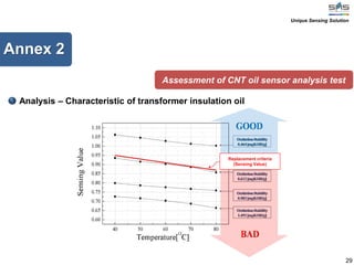
Assessment of CNT oil sensor analysis test
Sensing Rate of CNT Sensor
OxidationStability
[mgKOH/g]
DielectricStrength
[KV]
※ MICHANG OIL IND.CO.,LTD Analysis Data 2008.01
Unique Sensing Solution](https://image.slidesharecdn.com/t-1transformerinsulationoilsensingsystem-140805100840-phpapp02/85/T-1-transformer-insulation-oil-sensing-system-29-320.jpg)
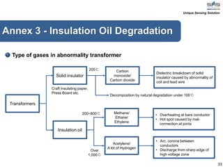

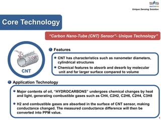
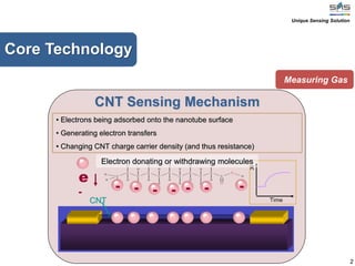
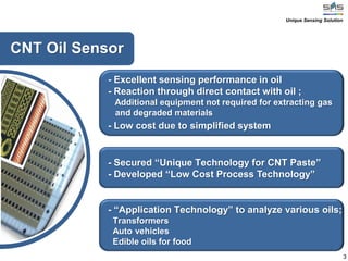
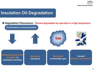
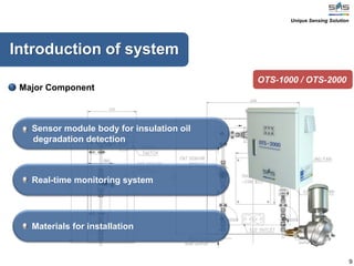
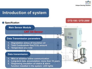
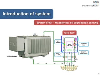
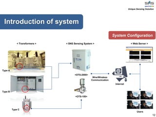
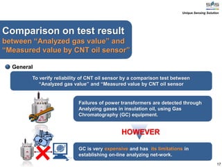
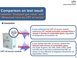
This document describes a carbon nanotube sensor system for monitoring transformer insulation oil. It consists of 3 sentences: The system uses a carbon nanotube sensor to detect combustible gases produced from degradation of insulation oil. It can continuously monitor multiple transformers in real-time through a wireless network. Test results showed the carbon nanotube sensor accurately measured changes in combustible gases compared to gas chromatography analysis.


