Downloaded 1,340 times

![[1] Dr. P. S. Bhimbra, “Electrical Machines”, Khanna
Publications, New Delhi.
[2] D. P. Kothari and I. J. Nagrath, “Electrical Machines” , 3rd
Edition, TMH, New Delhi.
[3] BHEL , “Transformers” 2nd Edition ,Tata Mcgraw Hill
Education Private Limited.
REFERENCES](https://image.slidesharecdn.com/mandeep-141219132826-conversion-gate02/85/Summer-traning-on-Power-Transformer-Construction-26-320.jpg)


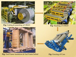
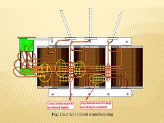
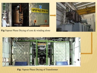
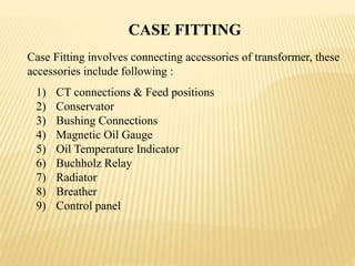
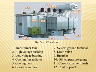
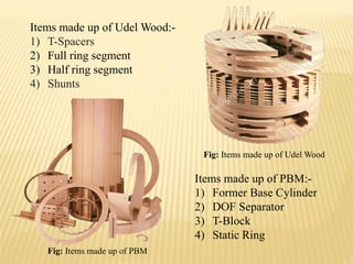
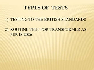
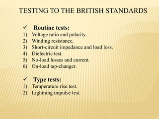
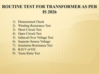
The document summarizes an industrial training seminar on transformer construction held at BHEL Bhopal from May 29th to June 25th, 2014. It was presented by Mandeep Singh, an electrical engineering final year student from B.I.E.T Jhansi, under the guidance of Shri Shailendra Kumar Somi from BHEL Bhopal. The seminar covered topics such as transformer core building, winding, coil assembly, power assembly, case fitting, insulation, testing, and dispatch. It provided details on the manufacturing process and testing standards for power transformers.


![Transformer Repair Workshop Report [EEE]](https://cdn.slidesharecdn.com/ss_thumbnails/transformerrepairworkshopeee-140621072318-phpapp01-thumbnail.jpg?width=640&height=640&fit=bounds)