Download to read offline

![Case Study Of the Failed 15.75/220kV, 250MVA Generator Transformer: An Overview
DOI: 10.9790/1676-10514852 www.iosrjournals.org 52 | Page
failure and in case of such failures with Generator transformers leads to loss of generation resulting in both
Generation Losses and equipment loss. Some times these failures may cause secondary damages also e.g.
damages to nearby equipments and humans. Therefore After samples have been taken and analyzed, the first
step in evaluating DGA results is to consider the concentration levels (in ppm) of each key gas , if we found any
gases present at higher levels we should take immediate actions to resolve the problems.
References
[1]. Herbert G. Erdman (ed.), Electrical insulating oils, ASTM International, 1988 ISBN 0-8031-1179-7, p. 108
[2]. "DISSOLVED GAS ANALYSIS OF MINERAL OIL INSULATING FLUIDS". Retrieved November 2, 2011.
[3]. "Dissolved Gas Analysis". 2005 [last update]≤. Retrieved November 21, 2011
[4]. "Using Dissolved Gas Analysis to Detect Active Faults in Oil-Insulated Electrical Equipment". Retrieved November 21, 2011.
[5]. "DISSOLVED GAS ANALYSIS (DGA) OF INSULATING FLUIDS". Retrieved November 21, 2011.
[6]. Martin J. Heathcote (ed)., The J&P Transformer Book Thirteenth Edition, Newnes, 2007 ISBN 978-0-7506-8164-3 pages 588-615
[7]. "Dissolved Gas Analysis for Transformers" (PDF). Retrieved November 21, 2011.,Lynn Hamrick, "Dissolved Gas Analysis for
Transformers"](https://image.slidesharecdn.com/h010514852-160706050831/85/H010514852-5-320.jpg)

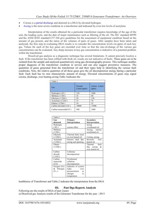
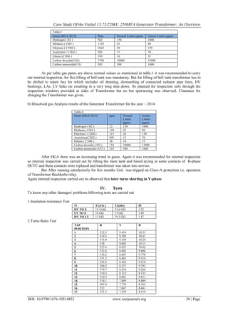
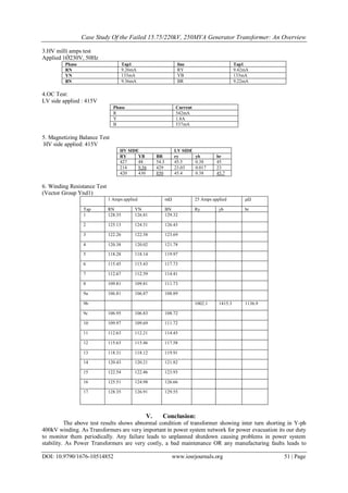
The document discusses a case study of a failed 250MVA generator transformer, analyzing dissolved gas test results from the transformer oil that indicated thermal faults and inter-turn shorting in the winding. Various tests were performed on the transformer, confirming inter-turn shorting in the Y-phase winding. The document emphasizes the importance of regularly monitoring transformers through dissolved gas analysis to detect problems early and avoid failures that can impact power system stability and lead to generation and equipment losses.