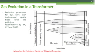
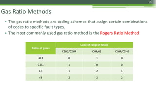
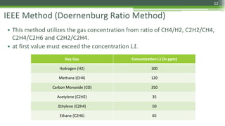
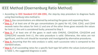
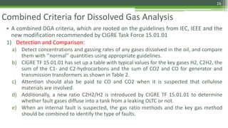
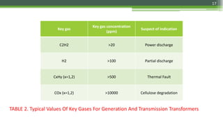
Dissolved Gas Analysis
By-
Ankit Singh Basera
1
Gas Evolution in a Transformer
2
• Internal faults in oil produce gaseous by products, including hydrogen (H2),
methane (CH4), acetylene (C2H2), ethylene (C2H4) and ethane (C2H6).
• The total of all combustible gases (TCG) with increases of gas generating rates
may indicate the existence of any one or a combination of thermal, electrical
or corona faults.
3
• Evaluation procedures
for DGA have been
implemented widely
based upon the
guidelines
recommended by IEC,
IEEE and CIGRE.
Hydrocarbon Gas Evolution In Transformer Oil Against Temperature
4
• The areas include normal operating temperatures go up to about 140 C, hot spots extend
to around 250 C and high temperature thermal faults to about 1000 C.
5
DGA Interpretation Methods
6
Key Gas Method
• The key gas method relates key gases to fault types and attempts to detect four fault types based
on key gas concentrations (C2H4, CO, H2, C2H2) expressed in ppm (part per million).
1) Overheating of oil: Decomposition products include C2H4 and CH4, together with small quantities
of H2 and C2H6. Traces of C2H2 may be formed if a fault is severe or involves electrical contacts.
The principal gas is C2H4.
2) Overheating of cellulose: Large quantities of CO2 and CO are evolved from overheated cellulose.
Hydrocarbon gases, such as CH4 and C2H4, are formed if a fault involves an oil-immersed
structure. The principal gas is CO.
3) Corona: Low-energy electrical discharges produce H2 and CH4, with small quantities of C2H6 and
C2H4. Comparable amounts of CO and CO2 may result from discharges in cellulose. The principal
gas is H2.
4) Arcing: Large amounts of H2 and C2H2 are produced, with minor quantities of CH4 and C2H4. CO2
and CO may also be formed if a fault involves cellulose. The insulation oil may be carbonised. The
principal gas is C2H2.
7
Sr No. Gas Fault Type
1 O2 and N2 non-faults
2 H2 corona
3 CO and CO2 overheating of cellulose insulation
4 CH4 and C2H6 low temperature overheating of oil
5 C2H4 high temperature overheating of oil
6 C2H2 arcing
 Since the key gas method does not give numerical correlations between fault types and gas types directly,
the diagnosis depends greatly on experience.
8
Combustible Gassing Rate
• Once a suspicious gas presence is detected, it is important to sample again
and calculate the gassing rate of a gas, which can indicate whether the fault
that generated the gas is active or not.
𝑅𝑖 =
𝐶𝑖2 − 𝐶𝑖1
𝛥𝑡
𝐺
𝜌
gassing rate (ml/h or day) second sample concentration (ppm)
first sample concentration (ppm)
total oil weight (ton)
Density of oil (ton/m3)
actual operating time of a sampling interval (hour or day)
9
Gas Ratio Methods
• The gas ratio methods are coding schemes that assign certain combinations
of codes to specific fault types.
• The most commonly used gas ratio method is the Rogers Ratio Method
Ratios of gases
Code of range of ratios
C2H2/C2H4 CH4/H2 C2H4/C2H6
<0.1 0 1 0
0.1/1 1 0 0
1-3 1 2 1
>3 2 2 2
10
Rogers Ratio Method
Cases Fault Characteristic
Code of Range of Ratios
Example
C2H2/C2H4 CH4/H2 C2H4/C2H6
0 No fault 0 0 0 Normal aging
1 Partial discharges of low energy density 0 1 0 Discharges in gas-filled cavities
2
Partial discharges of high energy
density
1 1 0
As above, but leading to tracking or
perforation of solid insulation
3 Discharge of low energy 1 0 1 Continuous sparking in oil
4 Discharge of high energy 1 0 2
Arcing - breakdown of oil between
windings or coils
5
Thermal fault of low Temperature
< 150 C
0 0 1
General insulated conductor
overheating
6
Thermal fault of low temperature range
150C–300C
0 2 0 Local overheating of the core due to
concentrations of flux. Increasing hot
spot temperatures; varying from
small hot spots in core, shorting links
in core, overheating of copper due
to eddy currents, bad contacts
7
Thermal fault of medium temperature
range 300C–700C
0 2 1
8
Thermal fault of high Temperature >
700C
0 2 2
11
IEEE Method (Doernenburg Ratio Method)
• This method utilizes the gas concentration from ratio of CH4/H2, C2H2/CH4,
C2H4/C2H6 and C2H2/C2H4.
• at first value must exceed the concentration L1.
Key Gas Concentration L1 (in ppm)
Hydrogen (H2) 100
Methane (CH4) 120
Carbon Monoxide (CO) 350
Acetylene (C2H2) 35
Ethylene (C2H4) 50
Ethane (C2H6) 65
12
IEEE Method (Doernenburg Ratio Method)
• According to IEEE Standard C57.104-1991, the step-by step procedure to diagnose faults
using Doernenburg ratio method is:
Step 1: Gas concentrations are obtained by extracting the gases and separating them.
Step 2: If at least one of the gas concentrations (in ppm) for H2, CH4, C2H2, and C2H4
exceeds twice the values for limit L1 and one of the other three gases exceeds the values
for limit L1, the unit is considered faulty; proceed to Step 3.
Step 3: If at least one of the gases in each ratio CH4/H2, C2H2/CH4, C2H2/CH4 and
C2H6/C2H2 exceeds limit L1, the ratio procedure is valid. Otherwise, the ratios are not
significant, and the unit should be resample and investigated by alternative procedures.
Step 4: Assuming that the ratio analysis is valid, each successive ratio is compared to the
standard values.
Step 5: If all succeeding ratios for a specific fault type fall within the values (column) given
in Table 1, the suggested diagnosis is valid.
13
Fault Diagnosis for Doernenburg Ratio Method
Suggested Fault
Diagnosis
Ratio (R1)
CH4/H2
Ratio (R2)
C2H2/C2H4
Ratio (R3)
C2H2/CH4
Ratio (R4)
C2H6/C2H2
Thermal
Decomposition
>1.0 >0.1 <0.75 <1.0 <0.3 <0.1 >0.4 >0.2
Corona (PD) <0.1 <0.01 Not Significant <0.3 <0.1 >0.4 >0.2
Arching 0.1<R1<1.0 0.01<R2<0.1 >0.75 >1.0 >0.3 >0.1 <0.4 <0.2
TABLE 1
14
Fault Detectability Using Dissolved Gas Analysis
• The majority of faults are slow to develop, which can be detected by DGA
monitoring.
• Locations of faults detectable using DGA as reported by CIGRE are:
1. Within a winding.
2. Cleats and leads.
3. In a tank.
4. A selector switch.
5. A core.
• However, instantaneous faults are rapid and sometimes cannot be predicted by
DGA. Instantaneous failures that cannot be prevented by DGA are:
1. Flash over with power follow-through.
2. Serious failures, developing within seconds to minutes and therefore not possible to be
detected using DGA.
15
Combined Criteria for Dissolved Gas Analysis
• A combined DGA criteria, which are rooted on the guidelines from IEC, IEEE and the
new modification recommended by CIGRE Task Force 15.01.01
1) Detection and Comparison:
a) Detect concentrations and gassing rates of any gases dissolved in the oil, and compare
them with ‘‘normal’’ quantities using appropriate guidelines.
b) CIGRE TF 15.01.01 has set up a table with typical values for the key gases H2, C2H2, the
sum of the C1- and C2-hydrocarbons and the sum of CO2 and CO for generator and
transmission transformers as shown in Table 2.
c) Attention should also be paid to CO and CO2 when it is suspected that cellulose
materials are involved.
d) Additionally, a new ratio C2H2/H2 is introduced by CIGRE TF 15.01.01 to determine
whether fault gases diffuse into a tank from a leaking OLTC or not.
e) When an internal fault is suspected, the gas ratio methods and the key gas method
should be combined to identify the type of faults.
16
Key gas
Key gas concentration
(ppm)
Suspect of indication
C2H2 >20 Power discharge
H2 >100 Partial discharge
CxHy (x=1,2) >500 Thermal Fault
COx (x=1,2) >10000 Cellulose degradation
TABLE 2. Typical Values Of Key Gases For Generation And Transmission Transformers
17
Combined Criteria for Dissolved Gas Analysis
2) Assessment: Based upon the combined assessment results using various
DGA guidelines, further inspections should be carried out to identify the
type and location of faults, such as tests of no-load characteristics of
winding DC resistance, insulation, partial discharge and humidity content
measurements.
3) Action: Recommended actions should be taken, such as increasing
surveillance, shortening sampling intervals, reducing the load on the
transformer and finally removing the unit from service.
18

Dissolved gas analysis

  • 1.
  • 2.
    Gas Evolution ina Transformer 2
  • 3.
    • Internal faultsin oil produce gaseous by products, including hydrogen (H2), methane (CH4), acetylene (C2H2), ethylene (C2H4) and ethane (C2H6). • The total of all combustible gases (TCG) with increases of gas generating rates may indicate the existence of any one or a combination of thermal, electrical or corona faults. 3
  • 4.
    • Evaluation procedures forDGA have been implemented widely based upon the guidelines recommended by IEC, IEEE and CIGRE. Hydrocarbon Gas Evolution In Transformer Oil Against Temperature 4
  • 5.
    • The areasinclude normal operating temperatures go up to about 140 C, hot spots extend to around 250 C and high temperature thermal faults to about 1000 C. 5
  • 6.
  • 7.
    Key Gas Method •The key gas method relates key gases to fault types and attempts to detect four fault types based on key gas concentrations (C2H4, CO, H2, C2H2) expressed in ppm (part per million). 1) Overheating of oil: Decomposition products include C2H4 and CH4, together with small quantities of H2 and C2H6. Traces of C2H2 may be formed if a fault is severe or involves electrical contacts. The principal gas is C2H4. 2) Overheating of cellulose: Large quantities of CO2 and CO are evolved from overheated cellulose. Hydrocarbon gases, such as CH4 and C2H4, are formed if a fault involves an oil-immersed structure. The principal gas is CO. 3) Corona: Low-energy electrical discharges produce H2 and CH4, with small quantities of C2H6 and C2H4. Comparable amounts of CO and CO2 may result from discharges in cellulose. The principal gas is H2. 4) Arcing: Large amounts of H2 and C2H2 are produced, with minor quantities of CH4 and C2H4. CO2 and CO may also be formed if a fault involves cellulose. The insulation oil may be carbonised. The principal gas is C2H2. 7
  • 8.
    Sr No. GasFault Type 1 O2 and N2 non-faults 2 H2 corona 3 CO and CO2 overheating of cellulose insulation 4 CH4 and C2H6 low temperature overheating of oil 5 C2H4 high temperature overheating of oil 6 C2H2 arcing  Since the key gas method does not give numerical correlations between fault types and gas types directly, the diagnosis depends greatly on experience. 8
  • 9.
    Combustible Gassing Rate •Once a suspicious gas presence is detected, it is important to sample again and calculate the gassing rate of a gas, which can indicate whether the fault that generated the gas is active or not. 𝑅𝑖 = 𝐶𝑖2 − 𝐶𝑖1 𝛥𝑡 𝐺 𝜌 gassing rate (ml/h or day) second sample concentration (ppm) first sample concentration (ppm) total oil weight (ton) Density of oil (ton/m3) actual operating time of a sampling interval (hour or day) 9
  • 10.
    Gas Ratio Methods •The gas ratio methods are coding schemes that assign certain combinations of codes to specific fault types. • The most commonly used gas ratio method is the Rogers Ratio Method Ratios of gases Code of range of ratios C2H2/C2H4 CH4/H2 C2H4/C2H6 <0.1 0 1 0 0.1/1 1 0 0 1-3 1 2 1 >3 2 2 2 10
  • 11.
    Rogers Ratio Method CasesFault Characteristic Code of Range of Ratios Example C2H2/C2H4 CH4/H2 C2H4/C2H6 0 No fault 0 0 0 Normal aging 1 Partial discharges of low energy density 0 1 0 Discharges in gas-filled cavities 2 Partial discharges of high energy density 1 1 0 As above, but leading to tracking or perforation of solid insulation 3 Discharge of low energy 1 0 1 Continuous sparking in oil 4 Discharge of high energy 1 0 2 Arcing - breakdown of oil between windings or coils 5 Thermal fault of low Temperature < 150 C 0 0 1 General insulated conductor overheating 6 Thermal fault of low temperature range 150C–300C 0 2 0 Local overheating of the core due to concentrations of flux. Increasing hot spot temperatures; varying from small hot spots in core, shorting links in core, overheating of copper due to eddy currents, bad contacts 7 Thermal fault of medium temperature range 300C–700C 0 2 1 8 Thermal fault of high Temperature > 700C 0 2 2 11
  • 12.
    IEEE Method (DoernenburgRatio Method) • This method utilizes the gas concentration from ratio of CH4/H2, C2H2/CH4, C2H4/C2H6 and C2H2/C2H4. • at first value must exceed the concentration L1. Key Gas Concentration L1 (in ppm) Hydrogen (H2) 100 Methane (CH4) 120 Carbon Monoxide (CO) 350 Acetylene (C2H2) 35 Ethylene (C2H4) 50 Ethane (C2H6) 65 12
  • 13.
    IEEE Method (DoernenburgRatio Method) • According to IEEE Standard C57.104-1991, the step-by step procedure to diagnose faults using Doernenburg ratio method is: Step 1: Gas concentrations are obtained by extracting the gases and separating them. Step 2: If at least one of the gas concentrations (in ppm) for H2, CH4, C2H2, and C2H4 exceeds twice the values for limit L1 and one of the other three gases exceeds the values for limit L1, the unit is considered faulty; proceed to Step 3. Step 3: If at least one of the gases in each ratio CH4/H2, C2H2/CH4, C2H2/CH4 and C2H6/C2H2 exceeds limit L1, the ratio procedure is valid. Otherwise, the ratios are not significant, and the unit should be resample and investigated by alternative procedures. Step 4: Assuming that the ratio analysis is valid, each successive ratio is compared to the standard values. Step 5: If all succeeding ratios for a specific fault type fall within the values (column) given in Table 1, the suggested diagnosis is valid. 13
  • 14.
    Fault Diagnosis forDoernenburg Ratio Method Suggested Fault Diagnosis Ratio (R1) CH4/H2 Ratio (R2) C2H2/C2H4 Ratio (R3) C2H2/CH4 Ratio (R4) C2H6/C2H2 Thermal Decomposition >1.0 >0.1 <0.75 <1.0 <0.3 <0.1 >0.4 >0.2 Corona (PD) <0.1 <0.01 Not Significant <0.3 <0.1 >0.4 >0.2 Arching 0.1<R1<1.0 0.01<R2<0.1 >0.75 >1.0 >0.3 >0.1 <0.4 <0.2 TABLE 1 14
  • 15.
    Fault Detectability UsingDissolved Gas Analysis • The majority of faults are slow to develop, which can be detected by DGA monitoring. • Locations of faults detectable using DGA as reported by CIGRE are: 1. Within a winding. 2. Cleats and leads. 3. In a tank. 4. A selector switch. 5. A core. • However, instantaneous faults are rapid and sometimes cannot be predicted by DGA. Instantaneous failures that cannot be prevented by DGA are: 1. Flash over with power follow-through. 2. Serious failures, developing within seconds to minutes and therefore not possible to be detected using DGA. 15
  • 16.
    Combined Criteria forDissolved Gas Analysis • A combined DGA criteria, which are rooted on the guidelines from IEC, IEEE and the new modification recommended by CIGRE Task Force 15.01.01 1) Detection and Comparison: a) Detect concentrations and gassing rates of any gases dissolved in the oil, and compare them with ‘‘normal’’ quantities using appropriate guidelines. b) CIGRE TF 15.01.01 has set up a table with typical values for the key gases H2, C2H2, the sum of the C1- and C2-hydrocarbons and the sum of CO2 and CO for generator and transmission transformers as shown in Table 2. c) Attention should also be paid to CO and CO2 when it is suspected that cellulose materials are involved. d) Additionally, a new ratio C2H2/H2 is introduced by CIGRE TF 15.01.01 to determine whether fault gases diffuse into a tank from a leaking OLTC or not. e) When an internal fault is suspected, the gas ratio methods and the key gas method should be combined to identify the type of faults. 16
  • 17.
    Key gas Key gasconcentration (ppm) Suspect of indication C2H2 >20 Power discharge H2 >100 Partial discharge CxHy (x=1,2) >500 Thermal Fault COx (x=1,2) >10000 Cellulose degradation TABLE 2. Typical Values Of Key Gases For Generation And Transmission Transformers 17
  • 18.
    Combined Criteria forDissolved Gas Analysis 2) Assessment: Based upon the combined assessment results using various DGA guidelines, further inspections should be carried out to identify the type and location of faults, such as tests of no-load characteristics of winding DC resistance, insulation, partial discharge and humidity content measurements. 3) Action: Recommended actions should be taken, such as increasing surveillance, shortening sampling intervals, reducing the load on the transformer and finally removing the unit from service. 18