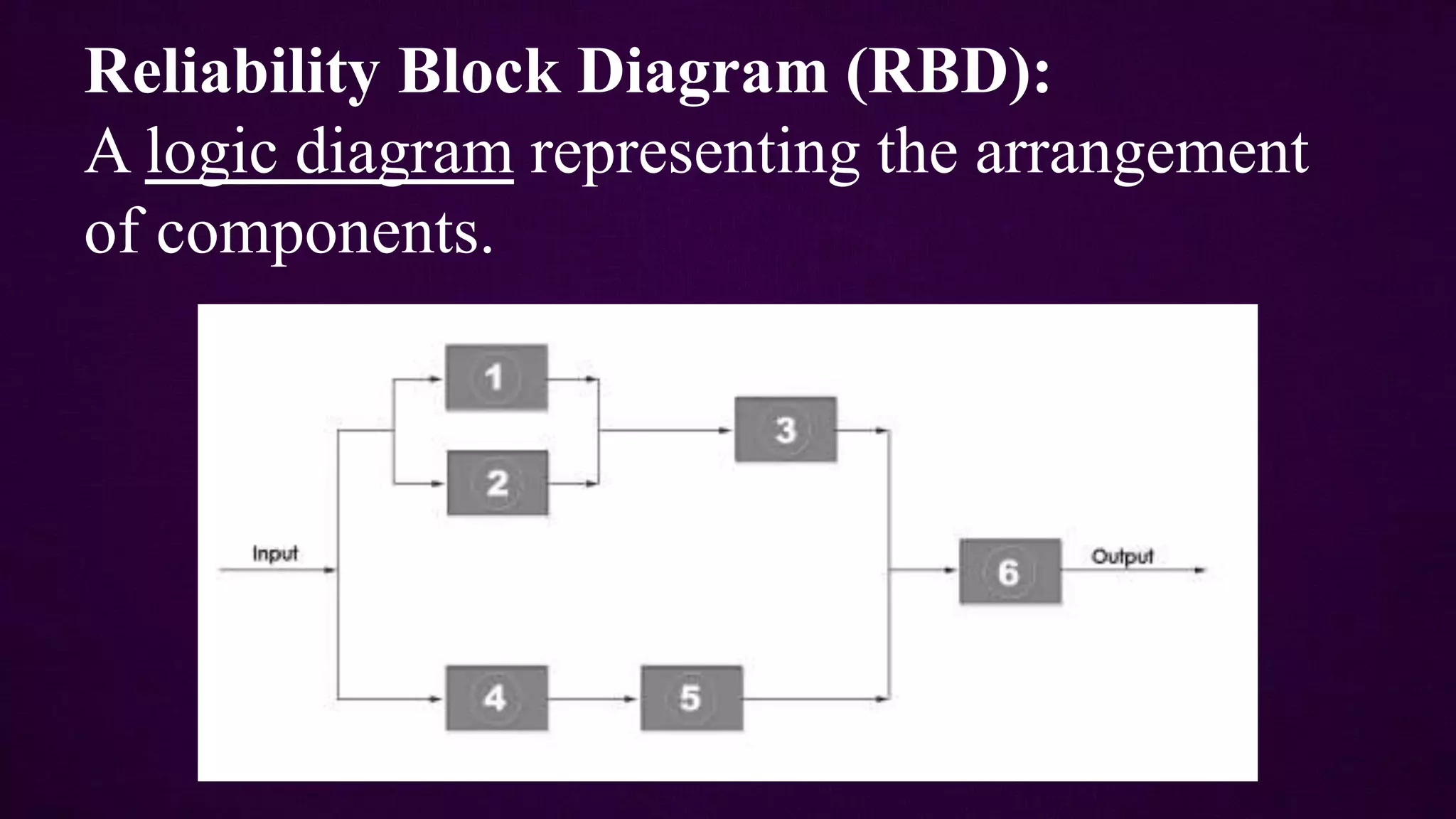
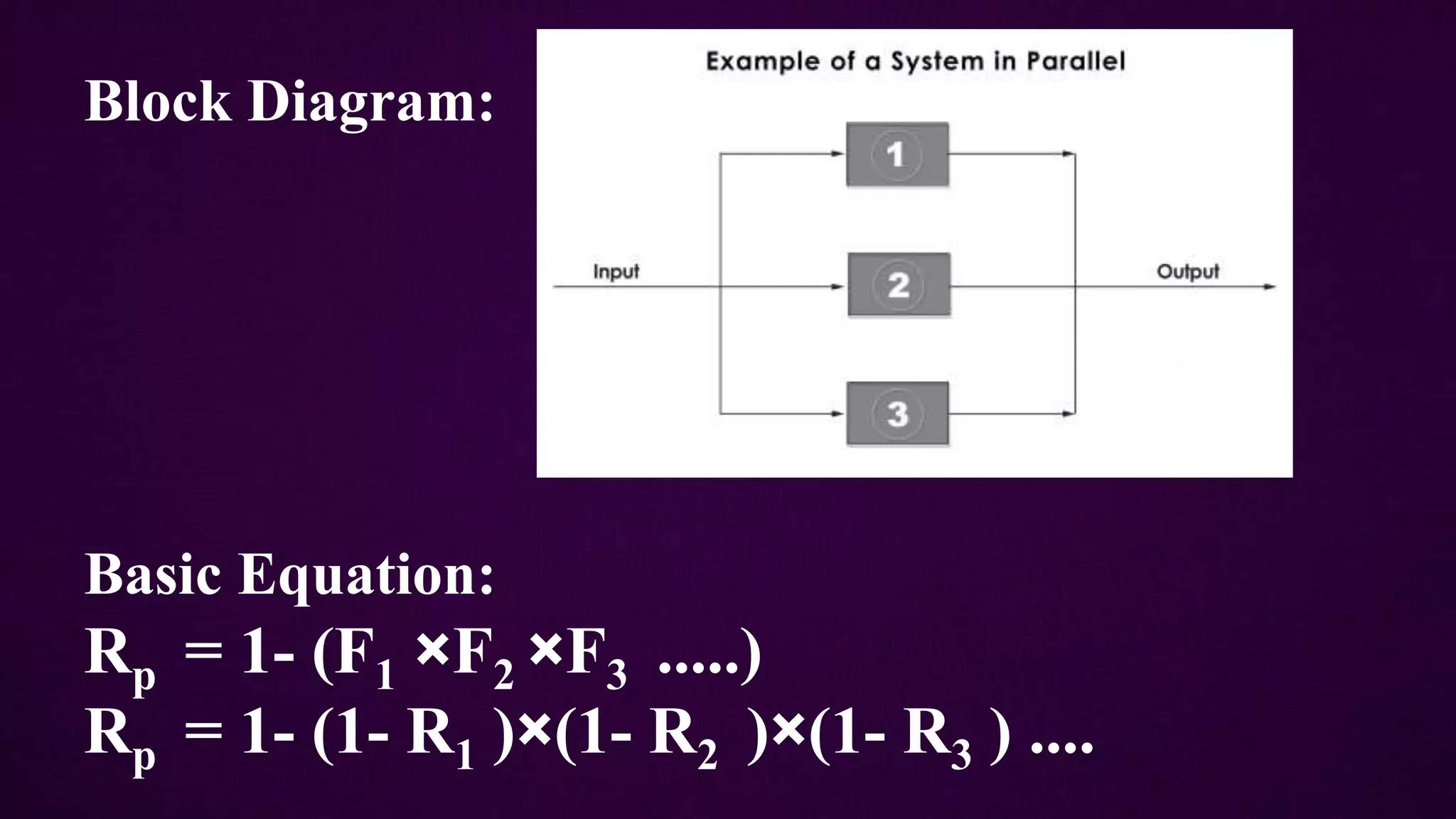
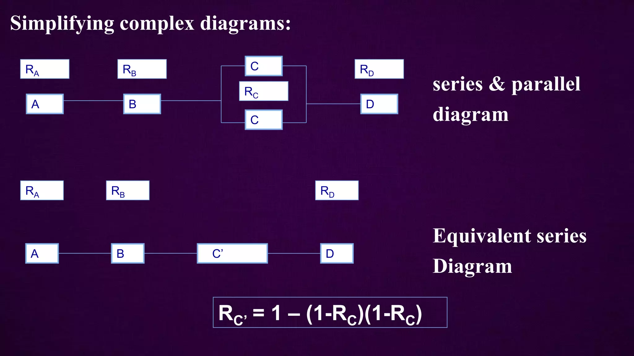
SYSTEM
RELIABILITY
Presented By:
Vikas M. Suroshe
College of Agricultural Engineering and Technology, Dr. PDKV,
Akola, 444104
Department of Farm Power and Machinery
 System:
A system is a collection of components, subsystems
and/or assemblies arranged to a specific design in order
to achieve desired functions with acceptable
performance and reliability.
system's reliability is affecetd by types of components,
their quantities, their qualities and the manner in which
they are arranged within the system
 Calculating Reliability Factor for
System:
Steps:
1. Identification of system units
2. logical representation as block or circuit diagram.
3. Determination of the conditions for successful
operation of the system.
4. Application of combinatorial rules of probability
theory.
 System Configurations Types:
1. Series Configuration
2. Parallel Configuration (Redundant System)
3. Mixed Configuration (Combine Series-
Parallel System)
Reliability Block Diagram (RBD):
A logic diagram representing the arrangement
of components.
Series Configuration:
In a series system, all components or subsystems must function for
the system to function.
A series system fails as long as any one of the components fails.
 Examples: Chains, gear train, Multi-Cell Battery, Computer
network etc.
Components attached in series will have an overall factor of safety
equivalent to weakest link.
It is important for all components to have a high reliability,
especially when the system has a large number of components.
Chain Gear train
in gearbox
Basic Equation:
Rs = R1×R2×R3 .... ×Rn
Block Diagram:
Reliabilitysystem = R1×R2×R3×R4
= 0.8×0.8×0.75×0.85
= 0.459
R1= 0.8 R2= 0.8 R3=0.75 R4=0.85
Example:
Reliability Consideration in Series-System Design:
• Two determinants of the system reliability of a series
system:
1. The component reliability level
2. The number of components
• The reliability of a series system can be improved by
1. Increasing the component reliability
1. Decreasing the number of series components
Parallel Configuration:
• In a parallel system, all components must fail for the system to fail.
• A parallel system works as long as any one of the components
works
• Probability of system failure (Fp) is product of probability of failure
of each component.
• Fp + Rp = 1 Where, Rp = Reliability of system in parallel
• System with 30% probability of failure has a 70% reliability.
• Examples: Jet engine, Braking systems, dual parallel hyadraulic
system on aeroplane etc.
Twin Engines on
Military Jet
Block Diagram:
Basic Equation:
Rp = 1- (F1 ×F2 ×F3 .....)
Rp = 1- (1- R1 )×(1- R2 )×(1- R3 ) ....
Advantages:
• To improve reliability of the system by making some
of the equipment redundant to the other.
• It gives more safety for systems where human lives
are involved.
• Necessary arrangements can be done without stopping
the ongoing work. Specially in production units.
• Parallel-system is a means for increasing reliability.
• Added cost of redundancy.
• May not be feasible or possible from a design
standpoint.
• In highly reliable systems the gains will be small.
• May exceed weight and size limitations.
• Power consumption may be increased.
Disadvantages of parallel system:
Example:
Reliabilitysystem = 1- {(1- R1 )×(1- R2 )×(1- R3 )×(1- R4 )}
= 1- {(1-0.9)(1-0.8)(1-0.85)(1-0.75) }
= 0.9925
R1 = 0.9
R1 = 0.8
R1 = 0.85
R1 = 0.75
Mixed Configuration:
• Elements are connected in series as well as parallel.
• Series and parallel structures are the basis for building more
complicated structures which use redundancy to increase
system reliability.
• The element could be dependent dissimilar units or
independent identical units.
Example of mixed configuration:
0.90 0.80
0.60
0.99
0.70
0.80
Reliability = 0.88×0.99×0.94
= 0.826
Simplifying complex diagrams:
series & parallel
diagram
Equivalent series
Diagram
A B
C
C
D
RA RB
RC
RD
A B C’ D
RA RB RD
RC’ = 1 – (1-RC)(1-RC)
System reliability and types of systems in machine design

System reliability and types of systems in machine design

  • 1.
    SYSTEM RELIABILITY Presented By: Vikas M.Suroshe College of Agricultural Engineering and Technology, Dr. PDKV, Akola, 444104 Department of Farm Power and Machinery
  • 2.
     System: A systemis a collection of components, subsystems and/or assemblies arranged to a specific design in order to achieve desired functions with acceptable performance and reliability. system's reliability is affecetd by types of components, their quantities, their qualities and the manner in which they are arranged within the system
  • 3.
     Calculating ReliabilityFactor for System: Steps: 1. Identification of system units 2. logical representation as block or circuit diagram. 3. Determination of the conditions for successful operation of the system. 4. Application of combinatorial rules of probability theory.
  • 4.
     System ConfigurationsTypes: 1. Series Configuration 2. Parallel Configuration (Redundant System) 3. Mixed Configuration (Combine Series- Parallel System)
  • 5.
    Reliability Block Diagram(RBD): A logic diagram representing the arrangement of components.
  • 6.
    Series Configuration: In aseries system, all components or subsystems must function for the system to function. A series system fails as long as any one of the components fails.  Examples: Chains, gear train, Multi-Cell Battery, Computer network etc. Components attached in series will have an overall factor of safety equivalent to weakest link. It is important for all components to have a high reliability, especially when the system has a large number of components.
  • 7.
  • 8.
    Basic Equation: Rs =R1×R2×R3 .... ×Rn Block Diagram:
  • 9.
    Reliabilitysystem = R1×R2×R3×R4 =0.8×0.8×0.75×0.85 = 0.459 R1= 0.8 R2= 0.8 R3=0.75 R4=0.85 Example:
  • 10.
    Reliability Consideration inSeries-System Design: • Two determinants of the system reliability of a series system: 1. The component reliability level 2. The number of components • The reliability of a series system can be improved by 1. Increasing the component reliability 1. Decreasing the number of series components
  • 11.
    Parallel Configuration: • Ina parallel system, all components must fail for the system to fail. • A parallel system works as long as any one of the components works • Probability of system failure (Fp) is product of probability of failure of each component. • Fp + Rp = 1 Where, Rp = Reliability of system in parallel • System with 30% probability of failure has a 70% reliability. • Examples: Jet engine, Braking systems, dual parallel hyadraulic system on aeroplane etc.
  • 12.
  • 13.
    Block Diagram: Basic Equation: Rp= 1- (F1 ×F2 ×F3 .....) Rp = 1- (1- R1 )×(1- R2 )×(1- R3 ) ....
  • 14.
    Advantages: • To improvereliability of the system by making some of the equipment redundant to the other. • It gives more safety for systems where human lives are involved. • Necessary arrangements can be done without stopping the ongoing work. Specially in production units. • Parallel-system is a means for increasing reliability.
  • 15.
    • Added costof redundancy. • May not be feasible or possible from a design standpoint. • In highly reliable systems the gains will be small. • May exceed weight and size limitations. • Power consumption may be increased. Disadvantages of parallel system:
  • 16.
    Example: Reliabilitysystem = 1-{(1- R1 )×(1- R2 )×(1- R3 )×(1- R4 )} = 1- {(1-0.9)(1-0.8)(1-0.85)(1-0.75) } = 0.9925 R1 = 0.9 R1 = 0.8 R1 = 0.85 R1 = 0.75
  • 17.
    Mixed Configuration: • Elementsare connected in series as well as parallel. • Series and parallel structures are the basis for building more complicated structures which use redundancy to increase system reliability. • The element could be dependent dissimilar units or independent identical units.
  • 18.
    Example of mixedconfiguration: 0.90 0.80 0.60 0.99 0.70 0.80 Reliability = 0.88×0.99×0.94 = 0.826
  • 19.
    Simplifying complex diagrams: series& parallel diagram Equivalent series Diagram A B C C D RA RB RC RD A B C’ D RA RB RD RC’ = 1 – (1-RC)(1-RC)