Redundancy in reliability engineering is the inclusion of extra (duplicate or backup) components or subsystems in a system, so that if one component fails, another can take over its function.
2
Redundancy in Reliability
Definition:
Redundancyin reliability engineering is the inclusion of extra (duplicate
or backup) components or subsystems in a system, so that if one
component fails, another can take over its function. This increases the
overall reliability and availability of the system.
Purpose of Redundancy
To reduce the probability of system failure. To maintain system
functionality even after component failures. To improve fault tolerance
and system safety. To achieve higher reliability without needing to
improve individual component reliability.
3.
3
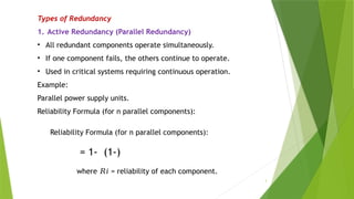
Types of Redundancy
1.Active Redundancy (Parallel Redundancy)
• All redundant components operate simultaneously.
• If one component fails, the others continue to operate.
• Used in critical systems requiring continuous operation.
Example:
Parallel power supply units.
Reliability Formula (for n parallel components):
Reliability Formula (for n parallel components):
= 1- (1-)
where = reliability of each component.
𝑅𝑖
4.
4
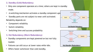
2. Standby (Cold)Redundancy
• Only one component operates at a time; others are kept in standby
mode.
• A switching mechanism activates a standby component upon failure.
• Standby parts are not subject to wear until activated.
Reliability depends on:
• Component reliability
• Switch reliability
• Switching time and success probability
3. Hot Redundancy (Warm Redundancy)
• Standby components are kept powered on but not fully
loaded.
• Failures can still occur at lower rates while idle.
• Offers faster switchover than cold standby.
5.
5
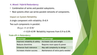
4. Mixed /Hybrid Redundancy
• Combination of series and parallel subsystems.
• Real systems often use series-parallel networks of components.
Impact on System Reliability
A single component with reliability =0.9
𝑅
Two such components in parallel:
𝑅𝑠𝑦𝑠 =1−(1−0.9)²
=1−0.01=0.99
Reliability improves from 0.9 to 0.99.
Trade-offs in Redundancy
Advantage Disadvantage
Improves reliability & safety Increases cost and weight
Reduces downtime Requires more space & power
Enhances fault tolerance May add complexity to design
Increases mission success Maintenance of extra parts needed
6.
6
Real-Life Examples
• Aircraftflight control systems with multiple redundant computers.
• Power plants having parallel backup generators.
• Data centers with RAID (redundant arrays of disks).
• Medical devices with redundant sensors.
Summary
• Redundancy is a key reliability engineering strategy where extra components are
added to ensure the system still functions if one part fails.
• It is crucial in safety-critical and mission-critical systems where downtime or
failure is unacceptable.
7.
7
⚡ Switching inStandby Redundancy
• In standby redundancy, only one unit is active at a time, and the others are kept off
(cold) until needed.
• If the active unit fails, a switching mechanism connects a standby unit to keep the
system running.
• The effectiveness of this switch is crucial and is described as perfect or imperfect
switching.
✅ Perfect Switching (Perfect Stitching)
Definition:
Perfect switching means the standby unit is always connected instantly and flawlessly
when the active unit fails.
Key Points:
Switch never fails.
Switching is instantaneous (no delay).
No loss of functionality or operation during switchover.
Assumption:
Switch reliability = 1
𝑅𝑠𝑤
Effect on Reliability:
System reliability depends only on the reliability of the units, not on the switch.
Used as an ideal assumption in theoretical reliability calculations.
8.
8
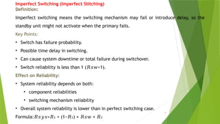
Imperfect Switching (ImperfectStitching)
Definition:
Imperfect switching means the switching mechanism may fail or introduce delay, so the
standby unit might not activate when the primary fails.
Key Points:
• Switch has failure probability.
• Possible time delay in switching.
• Can cause system downtime or total failure during switchover.
• Switch reliability is less than 1 ( <1).
𝑅𝑠𝑤
Effect on Reliability:
• System reliability depends on both:
• component reliabilities
• switching mechanism reliability
• Overall system reliability is lower than in perfect switching case.
Formula: = + (1− ) × ×
𝑅𝑠𝑦𝑠 𝑅 𝑅 𝑅𝑠𝑤 𝑅
₁ ₁ ₂
9.
9
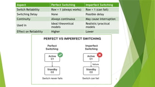
Aspect Perfect SwitchingImperfect Switching
Switch Reliability Rsw = 1 (always works) Rsw < 1 (can fail)
Switching Delay None Possible delay
Continuity Always continuous May cause interruption
Used in
Ideal/theoretical
models
Realistic/practical
models
Effect on Reliability Higher Lower
10.
10
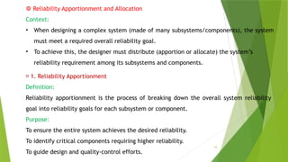
⚙️Reliability Apportionment andAllocation
Context:
• When designing a complex system (made of many subsystems/components), the system
must meet a required overall reliability goal.
• To achieve this, the designer must distribute (apportion or allocate) the system’s
reliability requirement among its subsystems and components.
📌 1. Reliability Apportionment
Definition:
Reliability apportionment is the process of breaking down the overall system reliability
goal into reliability goals for each subsystem or component.
Purpose:
To ensure the entire system achieves the desired reliability.
To identify critical components requiring higher reliability.
To guide design and quality-control efforts.
11.
11
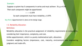
Example:
Suppose a systemhas 5 components in series and must achieve =0.90
𝑅𝑠𝑦𝑠
Then each component might be apportioned:
= = = 0.979
So each component must have reliability ≥ 0.979.
Key Point: Apportionment is done at the design stage.
📌 2. Reliability Allocation
Definition:
Reliability allocation is the practical assignment of reliability requirements to components,
considering their importance, complexity, and cost.
Unlike apportionment, which is a purely mathematical split, allocation:
Considers weighting factors (importance, cost, maturity, environment).Uses engineering
judgment and trade-offs.
12.
12
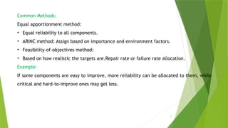
Common Methods:
Equal apportionmentmethod:
• Equal reliability to all components.
• ARINC method: Assign based on importance and environment factors.
• Feasibility-of-objectives method:
• Based on how realistic the targets are.Repair rate or failure rate allocation.
Example:
If some components are easy to improve, more reliability can be allocated to them, while
critical and hard-to-improve ones may get less.
13.
13
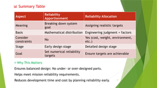
📊 Summary Table
Aspect
Reliability
Apportionment
ReliabilityAllocation
Meaning
Breaking down system
goal
Assigning realistic targets
Basis Mathematical distribution Engineering judgment + factors
Consider
constraints
No
Yes (cost, weight, environment,
etc.)
Stage Early design stage Detailed design stage
Goal
Set numerical reliability
targets
Ensure targets are achievable
📌 Why This Matters
Ensures balanced design: No under- or over-designed parts.
Helps meet mission reliability requirements.
Reduces development time and cost by planning reliability early.
14.
14
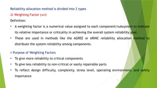
Reliability allocation methodis divided into 2 types
⚖️Weighting Factor ( i)
𝑤
Definition:
• A weighting factor is a numerical value assigned to each component/subsystem to indicate
its relative importance or criticality in achieving the overall system reliability goal.
• These are used in methods like the AGREE or ARINC reliability allocation method to
distribute the system reliability among components.
📌 Purpose of Weighting Factors
• To give more reliability to critical components
• To give less reliability to non-critical or easily repairable parts
• To reflect design difficulty, complexity, stress level, operating environment, and safety
importance
15.
15
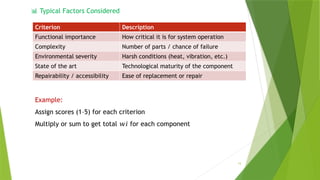
📊 Typical FactorsConsidered
Criterion Description
Functional importance How critical it is for system operation
Complexity Number of parts / chance of failure
Environmental severity Harsh conditions (heat, vibration, etc.)
State of the art Technological maturity of the component
Repairability / accessibility Ease of replacement or repair
Example:
Assign scores (1–5) for each criterion
Multiply or sum to get total for each component
𝑤𝑖
16.
16
📌 ARINC AllocationMethod (Aerospace Recommended Numbering Identification Code.)
= 1- ) * } /
where:
𝑅𝑖 = allocated reliability of component I
𝑤𝑖 = weighting factor𝑅𝑠𝑦𝑠
Rsys= required system reliability
⚙️AGREE Method (Advisory Group on Reliability of Electronic Equipment)
The AGREE Method is a classical and widely used reliability allocation method, developed by
the U.S. military’s Advisory Group on Reliability of Electronic Equipment (AGREE).
It is mainly used for series systems, and it allocates reliability goals to each subsystem
based on three main factors:
⚖️Basic Concept
Each subsystem is given a weight based on:
1. Number of parts ( )
𝑁𝑖
2. Complexity / Design factor (
)
𝐶𝑖
3. Importance factor ( )
𝐼𝑖
These are combined to get a weighting factor ( ), which is used to split the
𝑤𝑖 allowable failure rate
of the whole system.
17.
17
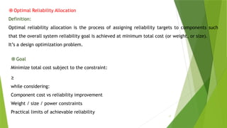
֎Optimal Reliability Allocation
Definition:
Optimalreliability allocation is the process of assigning reliability targets to components such
that the overall system reliability goal is achieved at minimum total cost (or weight, or size).
It’s a design optimization problem.
֎Goal
Minimize total cost subject to the constraint:
≥
while considering:
Component cost vs reliability improvement
Weight / size / power constraints
Practical limits of achievable reliability