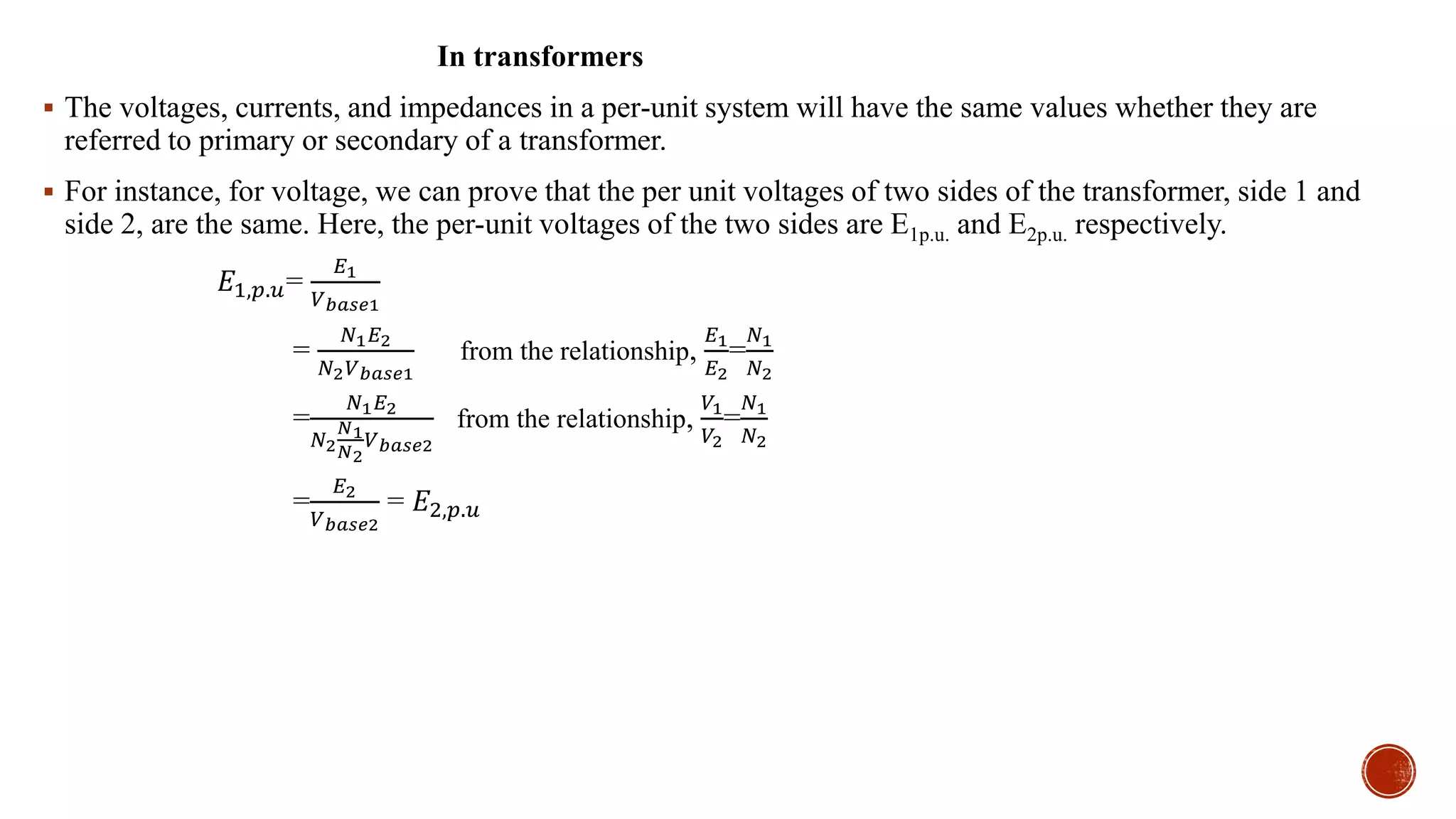
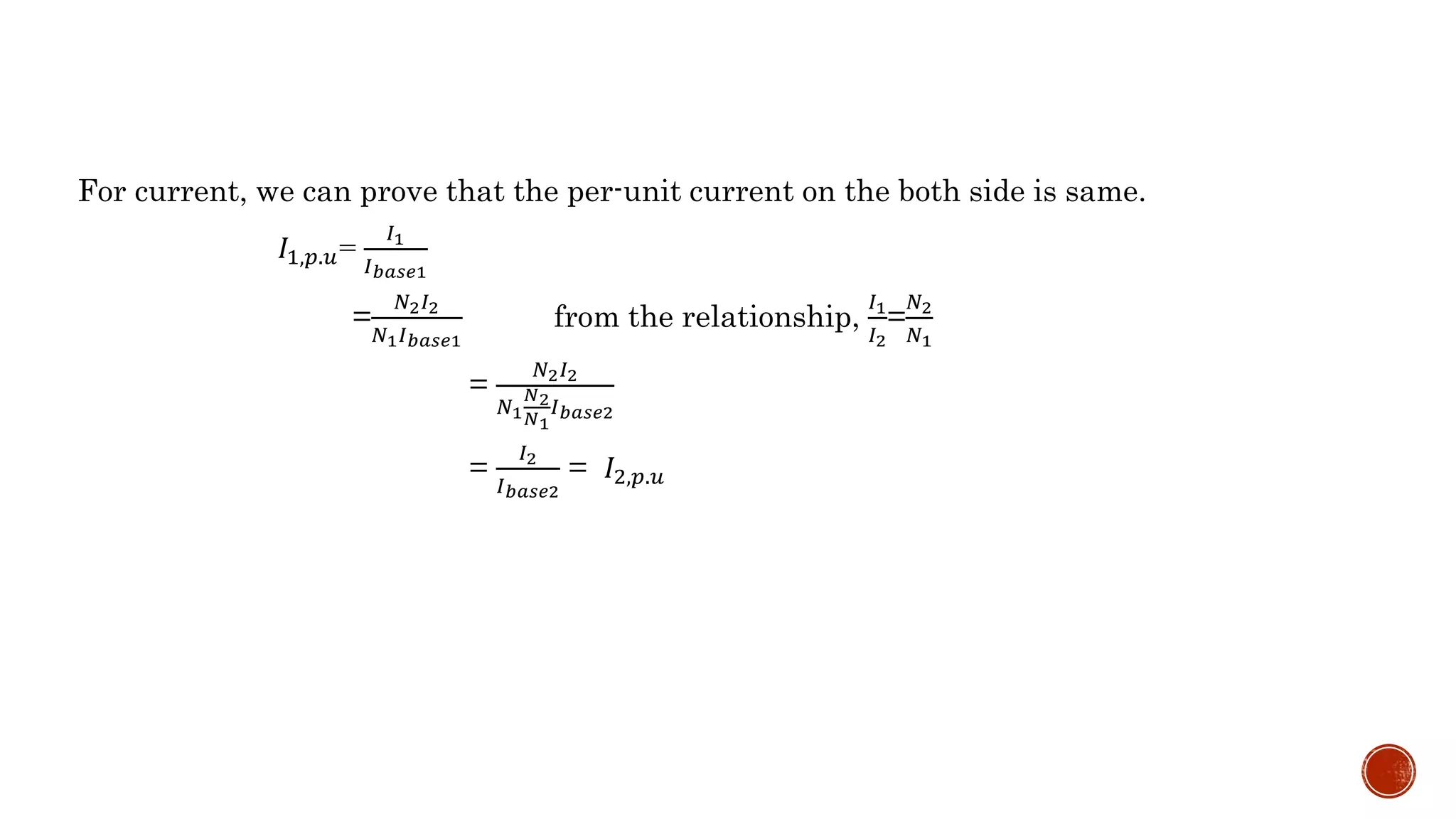
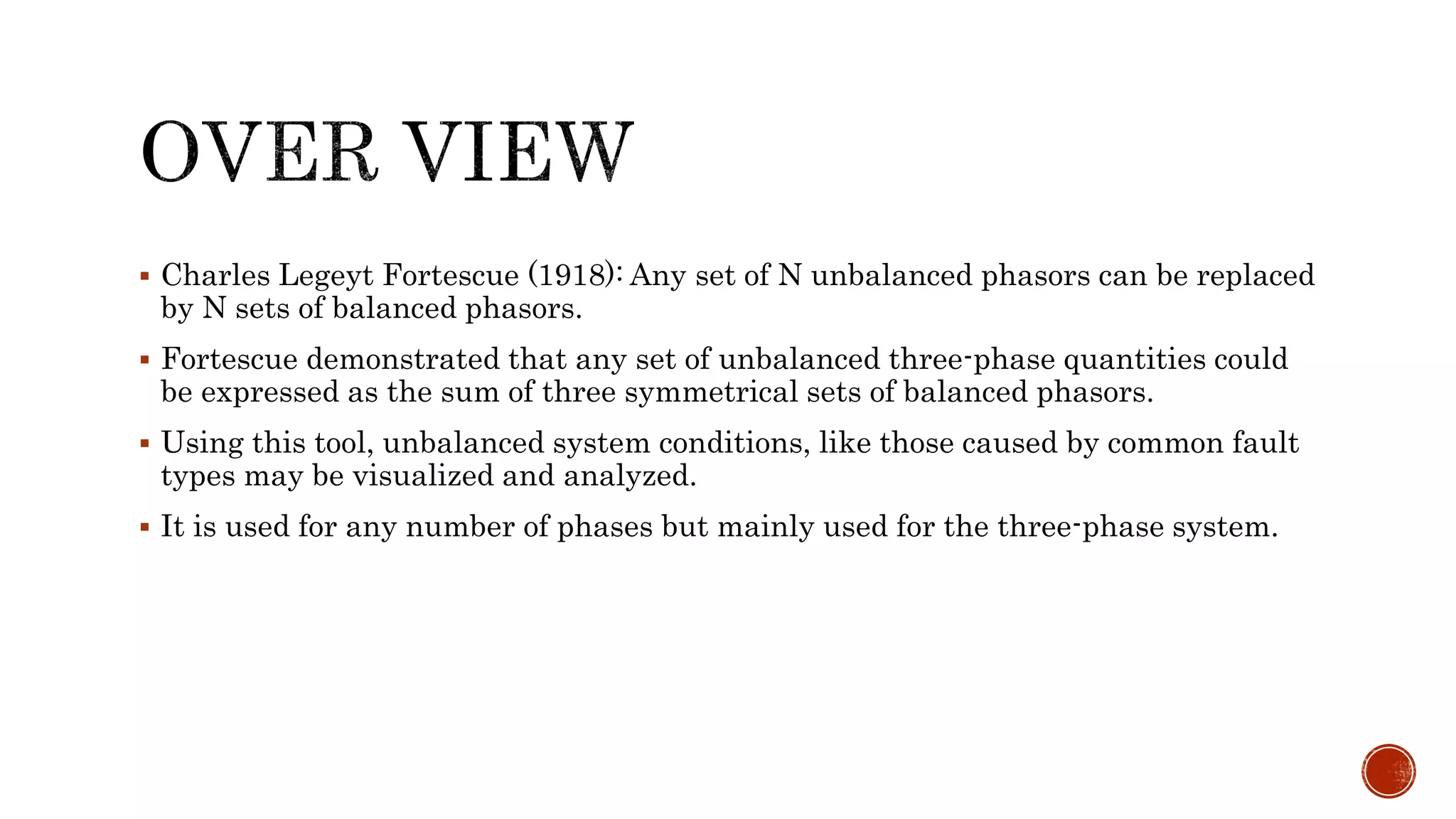
This document discusses per unit systems and symmetrical components for power system analysis. It defines a per unit system as expressing quantities as fractions of a defined base unit to simplify calculations when referring values across transformers. Advantages of per unit systems include similar impedances for similar apparatus and improved numerical stability. The document also defines symmetrical components as representing unbalanced three-phase quantities as the sum of three balanced components to analyze unbalanced faults.
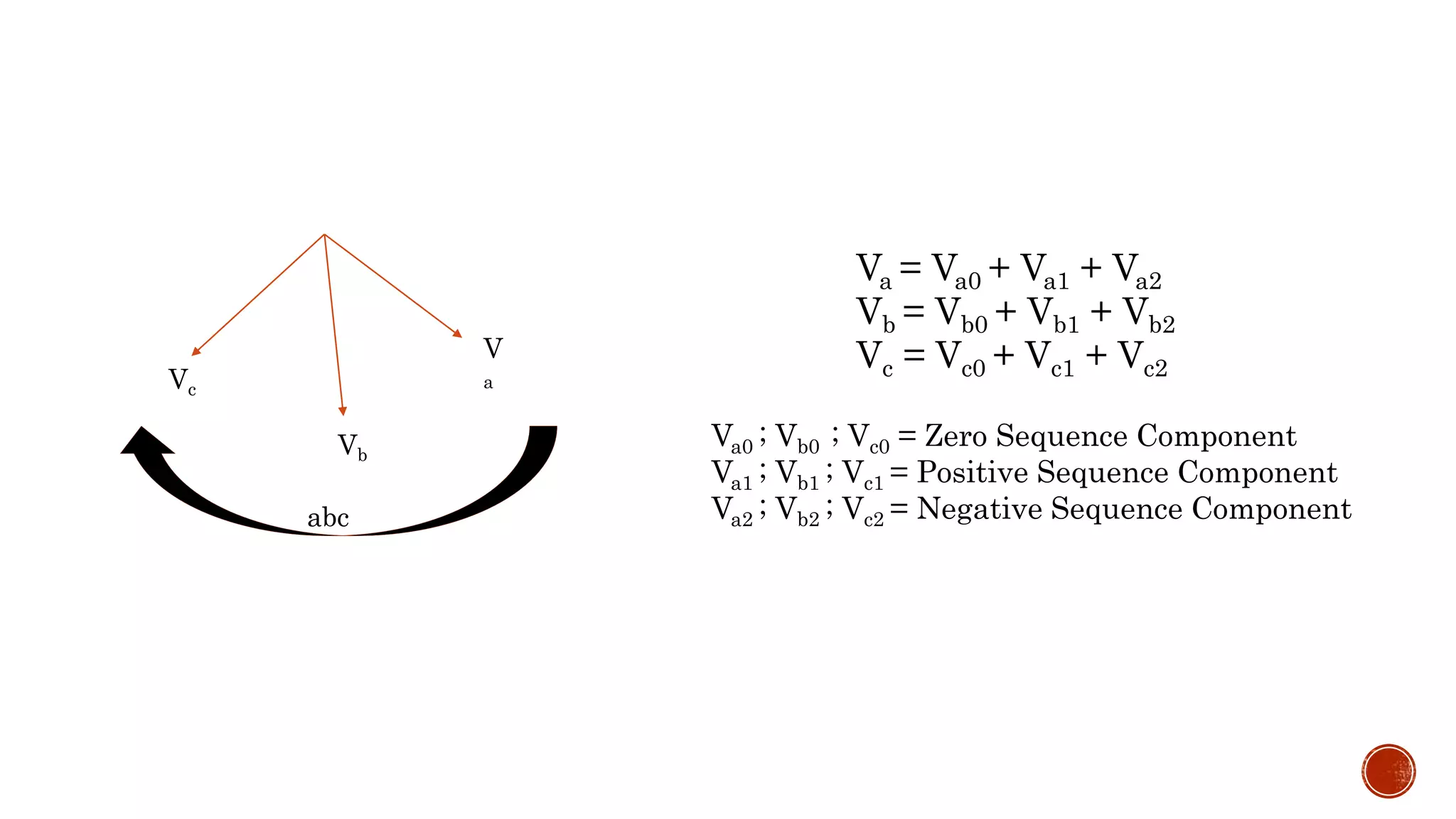
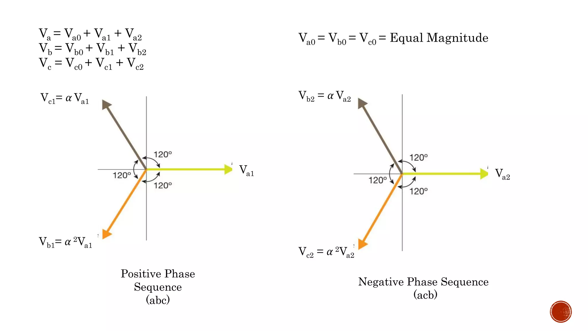
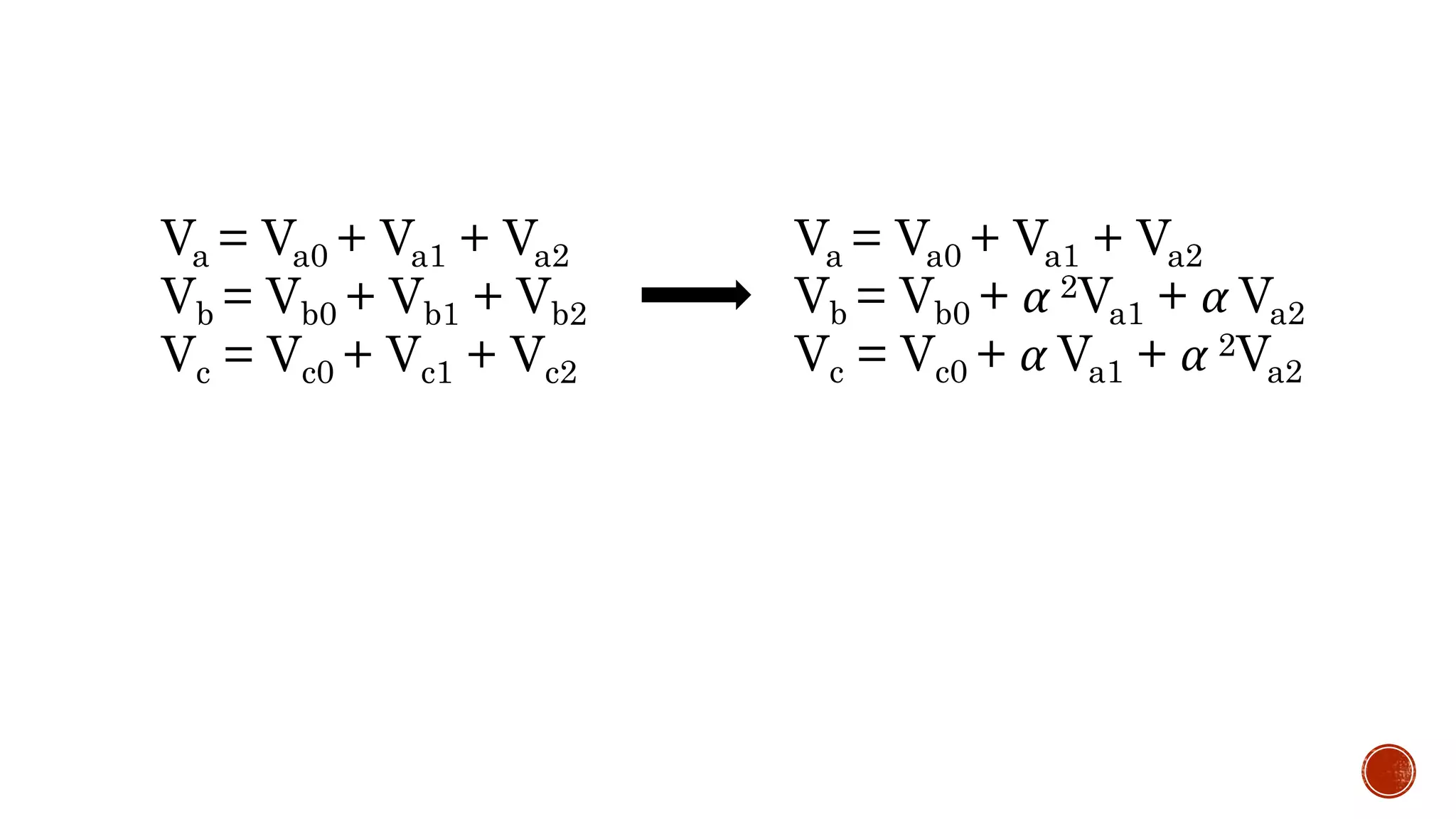
![Va = Va0 + Va1 + Va2
Vb = Vb0 + α 2Va1 + α Va2
Vc = Vc0 + α Va1 + α 2Va2
Va
Vb
Vc
=
1 1 1
1 𝑎2 𝑎
1 𝑎 𝑎2
𝑉𝑎0
𝑉𝑎1
𝑉𝑎2
[V]=[A][a]
[𝐴−1
][V] = [a]
1 1 1
1 𝑎2 𝑎
1 𝑎 𝑎2
−1
Va
Vb
Vc
=
𝑉𝑎0
𝑉𝑎1
𝑉𝑎2
1 1 1
1 𝑎2 𝑎
1 𝑎 𝑎2
−1
=
1
3
1 1 1
1 𝑎 𝑎2
1 𝑎2 𝑎
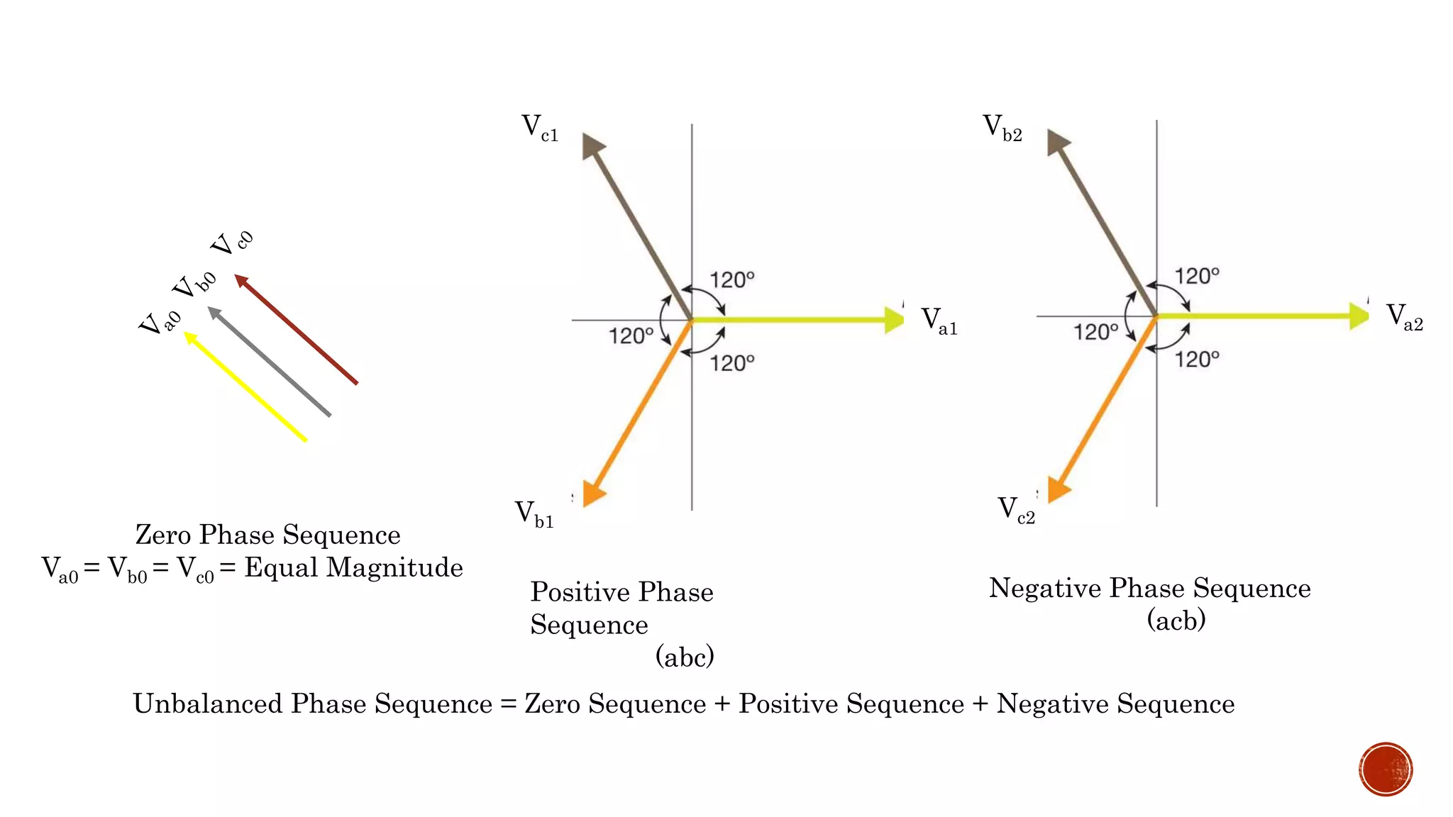
Va0 = Vb0 = Vc0 = Equal Magnitude](https://image.slidesharecdn.com/symmetricalcomponent-180326005156/75/Symmetrical-component-18-2048.jpg)
![𝑉𝑎0
𝑉𝑎1
𝑉𝑎2
=
1
3
1 1 1
1 𝑎 𝑎2
1 𝑎2
𝑎
Va
Vb
Vc
[𝑉𝑎0] =
1
3
[𝑉𝑎 + 𝑉𝑏+ 𝑉𝑐]
[𝑉𝑎2] =
1
3
[𝑉𝑎 + 𝑎2
𝑉𝑏+ 𝑎𝑉𝑐]
[𝑉𝑎1] =
1
3
[𝑉𝑎 + 𝑎𝑉𝑏+𝑎2 𝑉𝑐]](https://image.slidesharecdn.com/symmetricalcomponent-180326005156/75/Symmetrical-component-19-2048.jpg)