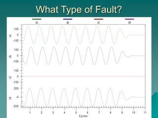
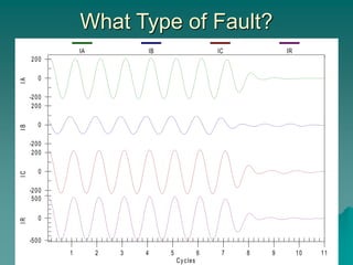
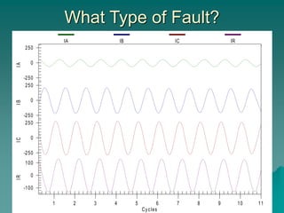
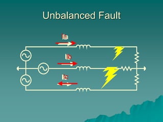
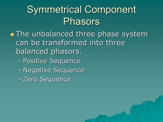
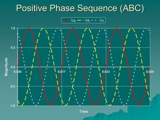
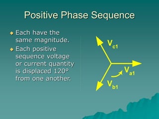
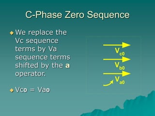
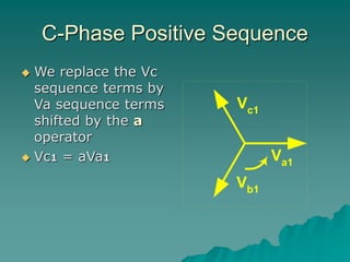
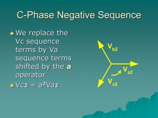
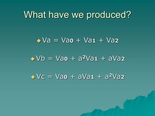
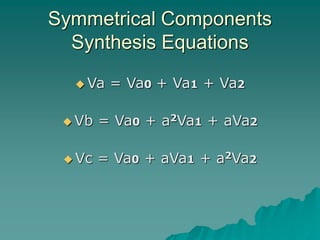
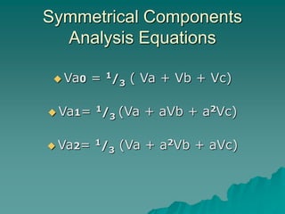
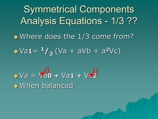
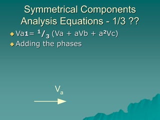
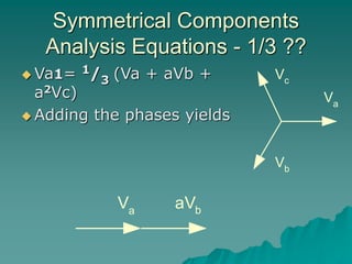
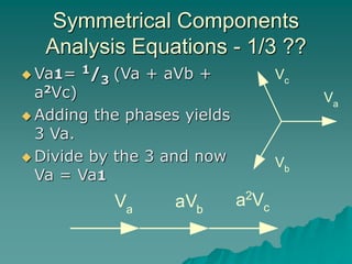
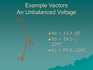
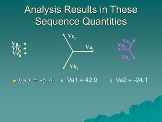
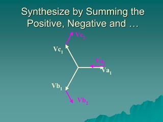
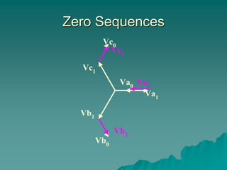
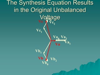
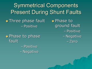
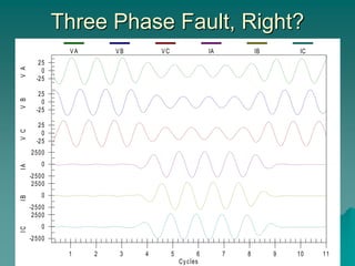
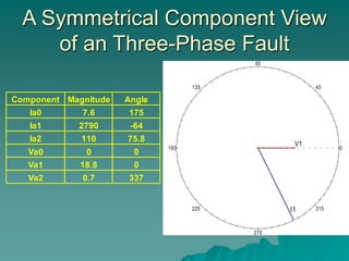
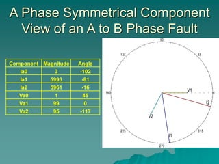
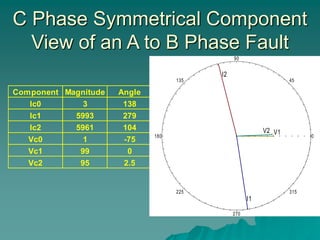
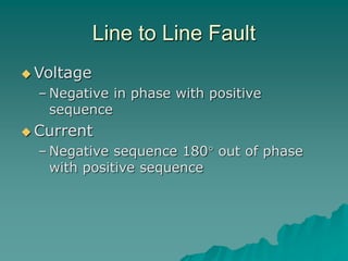
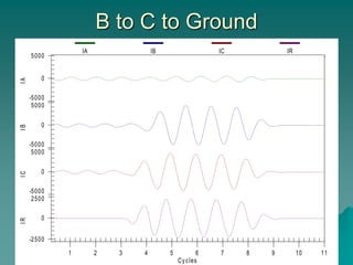
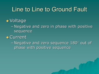
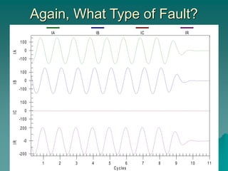
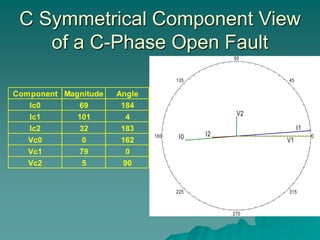
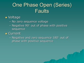
Symmetrical Components I
An Introduction to Power System Fault
Analysis Using Symmetrical Components
Dave Angell
Idaho Power
21st Annual
Hands-On Relay School
What Type of Fault?
-25
0
25
-25
0
25
-25
0
25
-2500
0
2500
-2500
0
2500
-2500
0
2500
1 2 3 4 5 6 7 8 9 10 11
V
A
V
B
V
C
I
A
I
B
I
C
Cycles
VA VB VC IA IB IC
What Type of Fault?
-10000
0
10000
-10000
0
10000
-10000
0
10000
-10000
0
10000
1 2 3 4 5 6 7 8 9 10 11
I
A
I
B
I
C
I
R
Cycles
IA IB IC IR
What Type of Fault?
-10000
0
10000
-10000
0
10000
-10000
0
10000
1 2 3 4 5 6 7 8 9 10 11
I
A
I
B
I
C
Cycles
IA IB IC
What Type of Fault?
-5000
0
5000
-5000
0
5000
-5000
0
5000
-2500
0
2500
1 2 3 4 5 6 7 8 9 10 11
I
A
I
B
I
C
I
R
Cycles
IA IB IC IR
What Type of Fault?
-100
0
100
-100
0
100
-100
0
100
-200
-0
200
1 2 3 4 5 6 7 8 9 10 11
I
A
I
B
I
C
I
R
Cycles
IA IB IC IR
What Type of Fault?
-200
0
200
-200
0
200
-200
0
200
-500
0
500
1 2 3 4 5 6 7 8 9 10 11
I
A
I
B
I
C
I
R
Cycles
IA IB IC IR
What Type of Fault?
-250
0
250
-250
0
250
-250
0
250
-100
0
100
1 2 3 4 5 6 7 8 9 10 11
I
A
I
B
I
C
I
R
Cycles
IA IB IC IR
Basic Course Topics
 Terminology
 Phasors
 Equations
 Fault Analysis Examples
 Calculations
Unbalanced Fault
Ia
Ib
Ic
Ia
Ib
Ic
Ia
Ib
Ic
Symmetrical Component
Phasors
 The unbalanced three phase system
can be transformed into three
balanced phasors.
– Positive Sequence
– Negative Sequence
– Zero Sequence
Positive Phase Sequence (ABC)
-1.0
-0.5
0.0
0.5
1.0
0.000 0.017 0.033 0.050
Time
Magnitude
Va Vb Vc
Positive Phase Sequence
 Each have the
same magnitude.
 Each positive
sequence voltage
or current quantity
is displaced 120°
from one another.
Va1
Vb1
Vc1
Positive Phase Sequence
 The positive
sequence
quantities have a-
b-c, counter clock-
wise, phase
rotation. Va1
Vb1
Vc1
Reverse Phase Sequence (ACB)
-1.0
-0.5
0.0
0.5
1.0
0.000 0.017 0.033 0.050
Time
Magnitude
Va Vb Vc
Negative Phase Sequence
 Each have the
same magnitude.
 Each negative
sequence voltage
or current quantity
is displaced 120°
from one another.
Va2
Vc2
Vb2
Negative Phase Sequence
 The negative
sequence
quantities have a-
c-b, counter clock-
wise, phase
rotation. Va2
Vc2
Vb2
Zero Phase Sequence
-1.0
-0.5
0.0
0.5
1.0
0.000 0.017 0.033 0.050
Time
Magnitude
Va Vb Vc
Zero Phase Sequence
 Each zero
sequence quantity
has the same
magnitude.
 All three phasors
with no angular
displacement
between them, all
in phase.
Va0
Vb0
Vc0
Symmetrical Components
Equations
 Each phase quantity is equal to the
sum of its symmetrical phasors.
 Va = Va0 + Va1 +Va2
 Vb = Vb0 + Vb1 +Vb2
 Vc = Vc0 + Vc1 +Vc2
 The common form of the equations
are written in a-phase terms.
The a Operator
 Used to shift the a-phase terms to
coincide with the b and c-phase
 Shorthand to indicate 120° rotation.
 Similar to the j operator of 90°.
Va
Rotation of the a Operator
 120° counter clock-wise rotation.
 A vector multiplied by 1 /120° results in
the same magnitude rotated 120°.
Va
aVa
Rotation of the a2 Operator
 240° counter clock-wise rotation.
 A vector multiplied by 1 /240° results in
the same magnitude rotated 240°.
Va
a2Va
B-Phase Zero Sequence
 We replace the
Vb sequence
terms by Va
sequence terms
shifted by the a
operator.
 Vb0 = Va0
Va0
Vb0
Vc0
B-Phase Positive Sequence
 We replace the Vb
sequence terms by
Va sequence terms
shifted by the a
operator
 Vb1 = a2Va1
Va1
Vb1
Vc1
B-Phase Negative Sequence
 We replace the Vb
sequence terms by
Va sequence terms
shifted by the a
operator
 Vb2 = aVa2 Va2
Vc2
Vb2
C-Phase Zero Sequence
 We replace the
Vc sequence
terms by Va
sequence terms
shifted by the a
operator.
 Vc0 = Va0
Va0
Vb0
Vc0
C-Phase Positive Sequence
 We replace the Vc
sequence terms by
Va sequence terms
shifted by the a
operator
 Vc1 = aVa1 Va1
Vb1
Vc1
C-Phase Negative Sequence
 We replace the
Vc sequence
terms by Va
sequence terms
shifted by the a
operator
 Vc2 = a2Va2
Va2
Vc2
Vb2
What have we produced?
 Va = Va0 + Va1 + Va2
 Vb = Va0 + a2Va1 + aVa2
 Vc = Va0 + aVa1 + a2Va2
Symmetrical Components
Equations
 Analysis
– To find out of the amount of the
components
 Synthesis
– The combining of the component
elements into a single, unified entity
Symmetrical Components
Synthesis Equations
 Va = Va0 + Va1 + Va2
 Vb = Va0 + a2Va1 + aVa2
 Vc = Va0 + aVa1 + a2Va2
Symmetrical Components
Analysis Equations
 Va0 = 1/3 ( Va + Vb + Vc)
 Va1= 1/3 (Va + aVb + a2Vc)
 Va2= 1/3 (Va + a2Vb + aVc)
Symmetrical Components
Analysis Equations - 1/3 ??
 Where does the 1/3 come from?
 Va1= 1/3 (Va + aVb + a2Vc)
 Va = Va0 + Va1 + Va2
 When balanced
0 0
Symmetrical Components
Analysis Equations - 1/3 ??
 Va1= 1/3 (Va + aVb + a2Vc)
 Adding the phases
Va
Symmetrical Components
Analysis Equations - 1/3 ??
 Va1= 1/3 (Va + aVb +
a2Vc)
 Adding the phases yields
Va
aVb
Vc
Va
Vb
Symmetrical Components
Analysis Equations - 1/3 ??
 Va1= 1/3 (Va + aVb +
a2Vc)
 Adding the phases yields
3 Va.
 Divide by the 3 and now
Va = Va1
a2
Vc
Va
aVb
Vc
Va
Vb
Example Vectors
An Unbalanced Voltage
Va
Vc
Vb
 Va = 13.4 /0°
 Vb = 59.6 /-
104°
 Vc = 59.6 /104°
Analysis Results in These
Sequence Quantities
Va0
Vb0
Vc0
Va2
Vc2
Vb2
Va1
Vb1
Vc1
 Va0 = -5.4 s Va1 = 42.9 s Va2 = -24.1
Synthesize by Summing the
Positive, Negative and …
Va2
Vb2
Vc2
Va1
Vb1
Vc1
Zero Sequences
Va2
Vb2
Vc2
Va0
Vb0
Vc0
Va1
Vb1
Vc1
The Synthesis Equation Results
in the Original Unbalanced
Voltage
Va2
Vb2
Vc2
Va0
Vb0
Vc0
Va1
Vb1
Vc1
Va
Vc
Vb
Symmetrical Components
Present During Shunt Faults
 Three phase fault
– Positive
 Phase to phase
fault
– Positive
– Negative
 Phase to
ground fault
– Positive
– Negative
– Zero
Symmetrical Component
Review of Faults Types
 Let’s return to the example fault
reports and view the sequence
quantities present
Three Phase Fault, Right?
-25
0
25
-25
0
25
-25
0
25
-2500
0
2500
-2500
0
2500
-2500
0
2500
1 2 3 4 5 6 7 8 9 10 11
V
A
V
B
V
C
I
A
I
B
I
C
Cycles
VA VB VC IA IB IC
A Symmetrical Component View
of an Three-Phase Fault
Component Magnitude Angle
Ia0 7.6 175
Ia1 2790 -64
Ia2 110 75.8
Va0 0 0
Va1 18.8 0
Va2 0.7 337
0
45
90
135
180
225
270
315
I1
V1
A to Ground Fault, Okay?
-10000
0
10000
-10000
0
10000
-10000
0
10000
-10000
0
10000
1 2 3 4 5 6 7 8 9 10 11
I
A
I
B
I
C
I
R
Cycles
IA IB IC IR
A Symmetrical Component View
of an A-Phase to Ground Fault
Component Magnitude Angle
Ia0 7340 -79
Ia1 6447 -79
Ia2 6539 -79
Va0 46 204
Va1 123 0
Va2 79 178
0
45
90
135
180
225
270
315
I0
I1
I2
V0 V1
V2
Single Line to Ground Fault
 Voltage
– Negative and zero sequence 180 out of
phase with positive sequence
 Current
– All sequence are in phase
A to B Fault, Easy?
-10000
0
10000
-10000
0
10000
-10000
0
10000
1 2 3 4 5 6 7 8 9 10 11
I
A
I
B
I
C
Cycles
IA IB IC
A Phase Symmetrical Component
View of an A to B Phase Fault
Component Magnitude Angle
Ia0 3 -102
Ia1 5993 -81
Ia2 5961 -16
Va0 1 45
Va1 99 0
Va2 95 -117
0
45
90
135
180
225
270
315
I1
I2
V1
V2
C Phase Symmetrical Component
View of an A to B Phase Fault
Component Magnitude Angle
Ic0 3 138
Ic1 5993 279
Ic2 5961 104
Vc0 1 -75
Vc1 99 0
Vc2 95 2.5
0
45
90
135
180
225
270
315
I1
I2
V1
V2
Line to Line Fault
 Voltage
– Negative in phase with positive
sequence
 Current
– Negative sequence 180 out of phase
with positive sequence
B to C to Ground
-5000
0
5000
-5000
0
5000
-5000
0
5000
-2500
0
2500
1 2 3 4 5 6 7 8 9 10 11
I
A
I
B
I
C
I
R
Cycles
IA IB IC IR
A Symmetrical Component View
of a B to C to Ground Fault
Component Magnitude Angle
Ia0 748 97
Ia1 2925 -75
Ia2 1754 101
Va0 8 351
Va1 101 0
Va2 18 348
0
45
90
135
180
225
270
315
I0
I1
I2
V0
V1
V2
Line to Line to Ground Fault
 Voltage
– Negative and zero in phase with positive
sequence
 Current
– Negative and zero sequence 180 out of
phase with positive sequence
Again, What Type of Fault?
-100
0
100
-100
0
100
-100
0
100
-200
-0
200
1 2 3 4 5 6 7 8 9 10 11
I
A
I
B
I
C
I
R
Cycles
IA IB IC IR
C Symmetrical Component View
of a C-Phase Open Fault
Component Magnitude Angle
Ic0 69 184
Ic1 101 4
Ic2 32 183
Vc0 0 162
Vc1 79 0
Vc2 5 90
0
45
90
135
180
225
270
315
I0
I1
I2
V1
V2
One Phase Open (Series)
Faults
 Voltage
– No zero sequence voltage
– Negative 90 out of phase with positive
sequence
 Current
– Negative and zero sequence 180 out of
phase with positive sequence
What About This One?
-200
0
200
-200
0
200
-200
0
200
-500
0
500
1 2 3 4 5 6 7 8 9 10 11
I
A
I
B
I
C
I
R
Cycles
IA IB IC IR
Ground Fault with Reverse Load
Ic0 164 -22
Ic1 89 -113
Ic2 41 -6
Vc0 4 -123
Vc1 38 0
Vc2 6 -130
0
45
90
135
180
225
270
315
I0
I1
I2
V0
V1
V2
Finally, The Last One!
-250
0
250
-250
0
250
-250
0
250
-100
0
100
1 2 3 4 5 6 7 8 9 10 11
I
A
I
B
I
C
I
R
Cycles
IA IB IC IR
Component Magnitude Angle
Ic0 45 40
Ic1 153 -4
Ic2 132 180
Vc0 0.5 331
Vc1 40 0
Vc2 0.5 93
Fault on Distribution System
with Delta – Wye Transformer
0
45
90
135
180
225
270
315
I0
I1
I2
V0
V1
V2
Use of Sequence Quantities in
Relays
 Zero Sequence filters
– Current
– Voltage
 Relay operating quantity
 Relay polarizing quantity
Zero Sequence Current
Ia
Ib
Ic
Direction of the
protected line
Ia+Ib+Ic
3I0
Zero Sequence Voltage
(Broken Delta)
Va
Vb
Vc
3V0
Zero Sequence Voltage
Va
Va
Vc
Vb
Va
Vb
3Vo
Va
Vb
Sequence Operating Quantities
 Zero and negative sequence currents
are not present during balanced
conditions.
 Good indicators of unbalanced faults
Sequence Polarizing Quantities
 Polarizing quantities are used to
determine direction.
 The quantities used must provide a
consistent phase relationship.
Zero Sequence Voltage
Polarizing
 3Vo is out of phase with Va
 -3Vo is used to polarize for ground faults
Va
Vb
3Vo
Learning Check
 Given three current sources
 How can zero sequence be produced
to test a relay?
 How can negative sequence
produced?
How can zero sequence be
produced to test a relay?
 A single source provides positive,
negative and zero sequence
– Note that each sequence quantity will
be 1/3 of the total current
 Connect the three sources in parallel
and set their amplitude and the
phase angle equal to one another
– The sequence quantities will be equal to
each source output
How can negative sequence
produced?
 A single source provides positive, negative
and zero sequence
– Each sequence quantity will be 1/3 of the total
current
 Set the three source’s amplitude equal to
one another and the phase angles to
produce a reverse phase sequence (Ia at
/0o
, Ib at /120o
and Ic at /-120o
)
– Only negative sequence will be produced
Advanced Course Topics
 Sequence Networks
 Connection of Networks for Faults
 Per Unit System
 Power System Element Models
References
 Symmetrical Components for Power
Systems Engineering, J Lewis
Blackburn
 Protective Relaying, J Lewis Blackburn
 Power System Analysis, Stevenson
 Analysis of Faulted Power System, Paul
Anderson
Conclusion
 Symmetrical components provide:
– balanced analysis of an unbalanced
system.
– a measure of system unbalance
– methods to detect faults
– an ability to distinguish fault direction

Symmetrical Components I 2004.ppt

  • 1.
    Symmetrical Components I AnIntroduction to Power System Fault Analysis Using Symmetrical Components Dave Angell Idaho Power 21st Annual Hands-On Relay School
  • 2.
    What Type ofFault? -25 0 25 -25 0 25 -25 0 25 -2500 0 2500 -2500 0 2500 -2500 0 2500 1 2 3 4 5 6 7 8 9 10 11 V A V B V C I A I B I C Cycles VA VB VC IA IB IC
  • 3.
    What Type ofFault? -10000 0 10000 -10000 0 10000 -10000 0 10000 -10000 0 10000 1 2 3 4 5 6 7 8 9 10 11 I A I B I C I R Cycles IA IB IC IR
  • 4.
    What Type ofFault? -10000 0 10000 -10000 0 10000 -10000 0 10000 1 2 3 4 5 6 7 8 9 10 11 I A I B I C Cycles IA IB IC
  • 5.
    What Type ofFault? -5000 0 5000 -5000 0 5000 -5000 0 5000 -2500 0 2500 1 2 3 4 5 6 7 8 9 10 11 I A I B I C I R Cycles IA IB IC IR
  • 6.
    What Type ofFault? -100 0 100 -100 0 100 -100 0 100 -200 -0 200 1 2 3 4 5 6 7 8 9 10 11 I A I B I C I R Cycles IA IB IC IR
  • 7.
    What Type ofFault? -200 0 200 -200 0 200 -200 0 200 -500 0 500 1 2 3 4 5 6 7 8 9 10 11 I A I B I C I R Cycles IA IB IC IR
  • 8.
    What Type ofFault? -250 0 250 -250 0 250 -250 0 250 -100 0 100 1 2 3 4 5 6 7 8 9 10 11 I A I B I C I R Cycles IA IB IC IR
  • 9.
    Basic Course Topics Terminology  Phasors  Equations  Fault Analysis Examples  Calculations
  • 10.
  • 11.
    Symmetrical Component Phasors  Theunbalanced three phase system can be transformed into three balanced phasors. – Positive Sequence – Negative Sequence – Zero Sequence
  • 12.
    Positive Phase Sequence(ABC) -1.0 -0.5 0.0 0.5 1.0 0.000 0.017 0.033 0.050 Time Magnitude Va Vb Vc
  • 13.
    Positive Phase Sequence Each have the same magnitude.  Each positive sequence voltage or current quantity is displaced 120° from one another. Va1 Vb1 Vc1
  • 14.
    Positive Phase Sequence The positive sequence quantities have a- b-c, counter clock- wise, phase rotation. Va1 Vb1 Vc1
  • 15.
    Reverse Phase Sequence(ACB) -1.0 -0.5 0.0 0.5 1.0 0.000 0.017 0.033 0.050 Time Magnitude Va Vb Vc
  • 16.
    Negative Phase Sequence Each have the same magnitude.  Each negative sequence voltage or current quantity is displaced 120° from one another. Va2 Vc2 Vb2
  • 17.
    Negative Phase Sequence The negative sequence quantities have a- c-b, counter clock- wise, phase rotation. Va2 Vc2 Vb2
  • 18.
    Zero Phase Sequence -1.0 -0.5 0.0 0.5 1.0 0.0000.017 0.033 0.050 Time Magnitude Va Vb Vc
  • 19.
    Zero Phase Sequence Each zero sequence quantity has the same magnitude.  All three phasors with no angular displacement between them, all in phase. Va0 Vb0 Vc0
  • 20.
    Symmetrical Components Equations  Eachphase quantity is equal to the sum of its symmetrical phasors.  Va = Va0 + Va1 +Va2  Vb = Vb0 + Vb1 +Vb2  Vc = Vc0 + Vc1 +Vc2  The common form of the equations are written in a-phase terms.
  • 21.
    The a Operator Used to shift the a-phase terms to coincide with the b and c-phase  Shorthand to indicate 120° rotation.  Similar to the j operator of 90°. Va
  • 22.
    Rotation of thea Operator  120° counter clock-wise rotation.  A vector multiplied by 1 /120° results in the same magnitude rotated 120°. Va aVa
  • 23.
    Rotation of thea2 Operator  240° counter clock-wise rotation.  A vector multiplied by 1 /240° results in the same magnitude rotated 240°. Va a2Va
  • 24.
    B-Phase Zero Sequence We replace the Vb sequence terms by Va sequence terms shifted by the a operator.  Vb0 = Va0 Va0 Vb0 Vc0
  • 25.
    B-Phase Positive Sequence We replace the Vb sequence terms by Va sequence terms shifted by the a operator  Vb1 = a2Va1 Va1 Vb1 Vc1
  • 26.
    B-Phase Negative Sequence We replace the Vb sequence terms by Va sequence terms shifted by the a operator  Vb2 = aVa2 Va2 Vc2 Vb2
  • 27.
    C-Phase Zero Sequence We replace the Vc sequence terms by Va sequence terms shifted by the a operator.  Vc0 = Va0 Va0 Vb0 Vc0
  • 28.
    C-Phase Positive Sequence We replace the Vc sequence terms by Va sequence terms shifted by the a operator  Vc1 = aVa1 Va1 Vb1 Vc1
  • 29.
    C-Phase Negative Sequence We replace the Vc sequence terms by Va sequence terms shifted by the a operator  Vc2 = a2Va2 Va2 Vc2 Vb2
  • 30.
    What have weproduced?  Va = Va0 + Va1 + Va2  Vb = Va0 + a2Va1 + aVa2  Vc = Va0 + aVa1 + a2Va2
  • 31.
    Symmetrical Components Equations  Analysis –To find out of the amount of the components  Synthesis – The combining of the component elements into a single, unified entity
  • 32.
    Symmetrical Components Synthesis Equations Va = Va0 + Va1 + Va2  Vb = Va0 + a2Va1 + aVa2  Vc = Va0 + aVa1 + a2Va2
  • 33.
    Symmetrical Components Analysis Equations Va0 = 1/3 ( Va + Vb + Vc)  Va1= 1/3 (Va + aVb + a2Vc)  Va2= 1/3 (Va + a2Vb + aVc)
  • 34.
    Symmetrical Components Analysis Equations- 1/3 ??  Where does the 1/3 come from?  Va1= 1/3 (Va + aVb + a2Vc)  Va = Va0 + Va1 + Va2  When balanced 0 0
  • 35.
    Symmetrical Components Analysis Equations- 1/3 ??  Va1= 1/3 (Va + aVb + a2Vc)  Adding the phases Va
  • 36.
    Symmetrical Components Analysis Equations- 1/3 ??  Va1= 1/3 (Va + aVb + a2Vc)  Adding the phases yields Va aVb Vc Va Vb
  • 37.
    Symmetrical Components Analysis Equations- 1/3 ??  Va1= 1/3 (Va + aVb + a2Vc)  Adding the phases yields 3 Va.  Divide by the 3 and now Va = Va1 a2 Vc Va aVb Vc Va Vb
  • 38.
    Example Vectors An UnbalancedVoltage Va Vc Vb  Va = 13.4 /0°  Vb = 59.6 /- 104°  Vc = 59.6 /104°
  • 39.
    Analysis Results inThese Sequence Quantities Va0 Vb0 Vc0 Va2 Vc2 Vb2 Va1 Vb1 Vc1  Va0 = -5.4 s Va1 = 42.9 s Va2 = -24.1
  • 40.
    Synthesize by Summingthe Positive, Negative and … Va2 Vb2 Vc2 Va1 Vb1 Vc1
  • 41.
  • 42.
    The Synthesis EquationResults in the Original Unbalanced Voltage Va2 Vb2 Vc2 Va0 Vb0 Vc0 Va1 Vb1 Vc1 Va Vc Vb
  • 43.
    Symmetrical Components Present DuringShunt Faults  Three phase fault – Positive  Phase to phase fault – Positive – Negative  Phase to ground fault – Positive – Negative – Zero
  • 44.
    Symmetrical Component Review ofFaults Types  Let’s return to the example fault reports and view the sequence quantities present
  • 45.
    Three Phase Fault,Right? -25 0 25 -25 0 25 -25 0 25 -2500 0 2500 -2500 0 2500 -2500 0 2500 1 2 3 4 5 6 7 8 9 10 11 V A V B V C I A I B I C Cycles VA VB VC IA IB IC
  • 46.
    A Symmetrical ComponentView of an Three-Phase Fault Component Magnitude Angle Ia0 7.6 175 Ia1 2790 -64 Ia2 110 75.8 Va0 0 0 Va1 18.8 0 Va2 0.7 337 0 45 90 135 180 225 270 315 I1 V1
  • 47.
    A to GroundFault, Okay? -10000 0 10000 -10000 0 10000 -10000 0 10000 -10000 0 10000 1 2 3 4 5 6 7 8 9 10 11 I A I B I C I R Cycles IA IB IC IR
  • 48.
    A Symmetrical ComponentView of an A-Phase to Ground Fault Component Magnitude Angle Ia0 7340 -79 Ia1 6447 -79 Ia2 6539 -79 Va0 46 204 Va1 123 0 Va2 79 178 0 45 90 135 180 225 270 315 I0 I1 I2 V0 V1 V2
  • 49.
    Single Line toGround Fault  Voltage – Negative and zero sequence 180 out of phase with positive sequence  Current – All sequence are in phase
  • 50.
    A to BFault, Easy? -10000 0 10000 -10000 0 10000 -10000 0 10000 1 2 3 4 5 6 7 8 9 10 11 I A I B I C Cycles IA IB IC
  • 51.
    A Phase SymmetricalComponent View of an A to B Phase Fault Component Magnitude Angle Ia0 3 -102 Ia1 5993 -81 Ia2 5961 -16 Va0 1 45 Va1 99 0 Va2 95 -117 0 45 90 135 180 225 270 315 I1 I2 V1 V2
  • 52.
    C Phase SymmetricalComponent View of an A to B Phase Fault Component Magnitude Angle Ic0 3 138 Ic1 5993 279 Ic2 5961 104 Vc0 1 -75 Vc1 99 0 Vc2 95 2.5 0 45 90 135 180 225 270 315 I1 I2 V1 V2
  • 53.
    Line to LineFault  Voltage – Negative in phase with positive sequence  Current – Negative sequence 180 out of phase with positive sequence
  • 54.
    B to Cto Ground -5000 0 5000 -5000 0 5000 -5000 0 5000 -2500 0 2500 1 2 3 4 5 6 7 8 9 10 11 I A I B I C I R Cycles IA IB IC IR
  • 55.
    A Symmetrical ComponentView of a B to C to Ground Fault Component Magnitude Angle Ia0 748 97 Ia1 2925 -75 Ia2 1754 101 Va0 8 351 Va1 101 0 Va2 18 348 0 45 90 135 180 225 270 315 I0 I1 I2 V0 V1 V2
  • 56.
    Line to Lineto Ground Fault  Voltage – Negative and zero in phase with positive sequence  Current – Negative and zero sequence 180 out of phase with positive sequence
  • 57.
    Again, What Typeof Fault? -100 0 100 -100 0 100 -100 0 100 -200 -0 200 1 2 3 4 5 6 7 8 9 10 11 I A I B I C I R Cycles IA IB IC IR
  • 58.
    C Symmetrical ComponentView of a C-Phase Open Fault Component Magnitude Angle Ic0 69 184 Ic1 101 4 Ic2 32 183 Vc0 0 162 Vc1 79 0 Vc2 5 90 0 45 90 135 180 225 270 315 I0 I1 I2 V1 V2
  • 59.
    One Phase Open(Series) Faults  Voltage – No zero sequence voltage – Negative 90 out of phase with positive sequence  Current – Negative and zero sequence 180 out of phase with positive sequence
  • 60.
    What About ThisOne? -200 0 200 -200 0 200 -200 0 200 -500 0 500 1 2 3 4 5 6 7 8 9 10 11 I A I B I C I R Cycles IA IB IC IR
  • 61.
    Ground Fault withReverse Load Ic0 164 -22 Ic1 89 -113 Ic2 41 -6 Vc0 4 -123 Vc1 38 0 Vc2 6 -130 0 45 90 135 180 225 270 315 I0 I1 I2 V0 V1 V2
  • 62.
    Finally, The LastOne! -250 0 250 -250 0 250 -250 0 250 -100 0 100 1 2 3 4 5 6 7 8 9 10 11 I A I B I C I R Cycles IA IB IC IR
  • 63.
    Component Magnitude Angle Ic045 40 Ic1 153 -4 Ic2 132 180 Vc0 0.5 331 Vc1 40 0 Vc2 0.5 93 Fault on Distribution System with Delta – Wye Transformer 0 45 90 135 180 225 270 315 I0 I1 I2 V0 V1 V2
  • 64.
    Use of SequenceQuantities in Relays  Zero Sequence filters – Current – Voltage  Relay operating quantity  Relay polarizing quantity
  • 65.
    Zero Sequence Current Ia Ib Ic Directionof the protected line Ia+Ib+Ic 3I0
  • 66.
    Zero Sequence Voltage (BrokenDelta) Va Vb Vc 3V0
  • 67.
  • 68.
    Sequence Operating Quantities Zero and negative sequence currents are not present during balanced conditions.  Good indicators of unbalanced faults
  • 69.
    Sequence Polarizing Quantities Polarizing quantities are used to determine direction.  The quantities used must provide a consistent phase relationship.
  • 70.
    Zero Sequence Voltage Polarizing 3Vo is out of phase with Va  -3Vo is used to polarize for ground faults Va Vb 3Vo
  • 71.
    Learning Check  Giventhree current sources  How can zero sequence be produced to test a relay?  How can negative sequence produced?
  • 72.
    How can zerosequence be produced to test a relay?  A single source provides positive, negative and zero sequence – Note that each sequence quantity will be 1/3 of the total current  Connect the three sources in parallel and set their amplitude and the phase angle equal to one another – The sequence quantities will be equal to each source output
  • 73.
    How can negativesequence produced?  A single source provides positive, negative and zero sequence – Each sequence quantity will be 1/3 of the total current  Set the three source’s amplitude equal to one another and the phase angles to produce a reverse phase sequence (Ia at /0o , Ib at /120o and Ic at /-120o ) – Only negative sequence will be produced
  • 74.
    Advanced Course Topics Sequence Networks  Connection of Networks for Faults  Per Unit System  Power System Element Models
  • 75.
    References  Symmetrical Componentsfor Power Systems Engineering, J Lewis Blackburn  Protective Relaying, J Lewis Blackburn  Power System Analysis, Stevenson  Analysis of Faulted Power System, Paul Anderson
  • 76.
    Conclusion  Symmetrical componentsprovide: – balanced analysis of an unbalanced system. – a measure of system unbalance – methods to detect faults – an ability to distinguish fault direction

Editor's Notes

  • #4 A Phase to Ground Fault
  • #5 A to B Phase Fault
  • #6 B to C to Ground Fault
  • #7 C Phase Open Fault
  • #51 A to B Phase Fault
  • #55 B to C to Ground Fault
  • #58 C Phase Open Fault