Downloaded 97 times


![Catalyst 1900 Management Console
Copyright (c) Cisco Systems, Inc. 1993-1999. All rights reserved.
Enterprise Edition Software
Ethernet Address:
00-D0-D3-74-ED-40
PCA Number:
73-3122-01
PCA Serial Number:
FAB032632C9
Model Number:
WS-C1912-EN
System Serial Number: FAB0328V07D
Power Supply S/N:
APQ0313014N
PCB Serial Number:
FAB032632C9,73-3122-04
------------------------------------------------1 user(s) now active on Management Console.
User Interface Menu
[M]
[K]
[I]
[P]
Menus
Command Line
IP Configuration
Console Password
Enter Selection: I
18](https://image.slidesharecdn.com/switching2-140104012956-phpapp02/85/Switching-2-18-320.jpg)
![Catalyst 1900 - IP Configuration
Ethernet Address: 00-D0-D3-74-ED-40
---------------------- Settings ----------------------[I] IP address
0.0.0.0
[S] Subnet mask
0.0.0.0
[G] Default gateway
0.0.0.0
[V] Management VLAN
1
[M] IP address of DNS server 1
0.0.0.0
[N] IP address of DNS server 2
0.0.0.0
[D] Domain name
[R] Use Routing Information Protocol
Enabled
-------------------- Actions -------------------------[P] Ping
[C] Clear cached DNS entries
[X] Exit to previous menu
I
Enter Selection:
19](https://image.slidesharecdn.com/switching2-140104012956-phpapp02/85/Switching-2-19-320.jpg)
![[D] Domain name
[R] Use Routing Information Protocol
Enabled
-------------------- Actions -------------------------[P] Ping
[C] Clear cached DNS entries
[X] Exit to previous menu
Enter Selection: I
This command assigns an administrative IP address to this switch.
The new address will take effect immediately. If no IP address is
assigned (or if the IP address is removed by setting it to
0.0.0.0), and the switch is connected to a DHCP server, the DHCP
server may automatically assign an address to the switch.
Enter administrative IP address in dotted format (nnn.nnn.nnn.nnn)
Current setting ===>
New setting
===>
0. 0. 0. 0
192.168.20.65
20](https://image.slidesharecdn.com/switching2-140104012956-phpapp02/85/Switching-2-20-320.jpg)
![Catalyst 1900 - IP Configuration
Ethernet Address: 00-D0-D3-74-ED-40
---------------------- Settings ---------------------------[I] IP address
192.168.20.65
[S] Subnet mask
0.0.0.0
[G] Default gateway
0.0.0.0
[V] Management VLAN
1
[M] IP address of DNS server 1
0.0.0.0
[N] IP address of DNS server 2
0.0.0.0
[D] Domain name
[R] Use Routing Information Protocol
Enabled
-------------------- Actions -----------------------------[P] Ping
[C] Clear cached DNS entries
[X] Exit to previous menu
S
Enter Selection:
21](https://image.slidesharecdn.com/switching2-140104012956-phpapp02/85/Switching-2-21-320.jpg)
![[M] IP address of DNS server 1
[N] IP address of DNS server 2
[D] Domain name
0.0.0.0
0.0.0.0
[R] Use Routing Information Protocol
Enabled
-------------------- Actions -------------------------[P] Ping
[C] Clear cached DNS entries
[X] Exit to previous menu
Enter Selection: I
This command defines the subnet mask for the IP address set by the
[I] IP Address command.
Enter IP subnet mask in dotted quad format (nnn.nnn.nnn.nnn):
Current setting ===>
New setting
0. 0. 0. 0
255.255.255.0
===>
22](https://image.slidesharecdn.com/switching2-140104012956-phpapp02/85/Switching-2-22-320.jpg)
![Catalyst 1900 - IP Configuration
Ethernet Address: 00-D0-D3-74-ED-40
---------------------- Settings ---------------------------[I] IP address
192.168.20.65
[S] Subnet mask
255.255.255.0
[G] Default gateway
0.0.0.0
[V] Management VLAN
1
[M] IP address of DNS server 1
0.0.0.0
[N] IP address of DNS server 2
0.0.0.0
[D] Domain name
[R] Use Routing Information Protocol
Enabled
-------------------- Actions -----------------------------[P] Ping
[C] Clear cached DNS entries
[X] Exit to previous menu
X
Enter Selection:
23](https://image.slidesharecdn.com/switching2-140104012956-phpapp02/85/Switching-2-23-320.jpg)
![Catalyst 1900 Management Console
Copyright (c) Cisco Systems, Inc. 1993-1999. All rights reserved.
Enterprise Edition Software
Ethernet Address:
00-D0-D3-74-ED-40
PCA Number:
73-3122-01
PCA Serial Number:
FAB032632C9
Model Number:
WS-C1912-EN
System Serial Number: FAB0328V07D
Power Supply S/N:
APQ0313014N
PCB Serial Number:
FAB032632C9,73-3122-04
------------------------------------------------1 user(s) now active on Management Console.
User Interface Menu
[M]
[K]
[I]
[P]
Menus
Command Line
IP Configuration
Console Password
Enter Selection: P
24](https://image.slidesharecdn.com/switching2-140104012956-phpapp02/85/Switching-2-24-320.jpg)
![User Interface Menu
[M]
[K]
[I]
[P]
Menus
Command Line
IP Configuration
Console Password
Enter Selection: P
The Management Console password can help prevent unauthorized
accesses. When specifying a password, use a minimum of
4
characters and maximum of 8 characters.
The password is case
insensitive and can contain any character with a legal keyboard
representation. For the user's protection, the password must be
entered the same way twice before it will be accepted.
Enter new password:
Reenter to verify new password:
****
****
Password modified
Press any key to continue.
25](https://image.slidesharecdn.com/switching2-140104012956-phpapp02/85/Switching-2-25-320.jpg)
![Catalyst 1900 Management Console
Copyright (c) Cisco Systems, Inc. 1993-1999. All rights reserved.
Enterprise Edition Software
Ethernet Address:
00-D0-D3-74-ED-40
PCA Number:
73-3122-01
PCA Serial Number:
FAB032632C9
Model Number:
WS-C1912-EN
System Serial Number: FAB0328V07D
Power Supply S/N:
APQ0313014N
PCB Serial Number:
FAB032632C9,73-3122-04
------------------------------------------------1 user(s) now active on Management Console.
User Interface Menu
[M] Menus
[K] Command Line
Enter Selection: M
Enter password: ****
26](https://image.slidesharecdn.com/switching2-140104012956-phpapp02/85/Switching-2-26-320.jpg)
![Catalyst 1900 - Main Menu
[C]
[S]
[N]
[P]
[A]
[D]
[M]
[V]
[R]
[F]
[I]
[U]
[H]
[K]
Console Settings
System
Network Management
Port Configuration
Port Addressing
Port Statistics Detail
Monitoring
Virtual LAN
Multicast Registration
Firmware
RS-232 Interface
Usage Summaries
Help
Command Line
[X] Exit Management Console
Enter Selection: S
27](https://image.slidesharecdn.com/switching2-140104012956-phpapp02/85/Switching-2-27-320.jpg)
![Catalyst 1900 - System Configuration
System Revision: 5
Address Capacity: 1024
System UpTime:
0day(s) 00hour(s) 06minute(s) 58second(s)
---------------------- Settings ------------------------------[N] Name of system
Switch
[C] Contact name
[L] Location
[S] Switching mode
FragmentFree
[U] Use of store-and-forward for multicast
Disabled
[A] Action upon address violation
Suspend
[G] Generate alert on address violation
Enabled
[I] Address aging time
300 second(s)
[P] Network port
None
[H] Half duplex back pressure
(10-mbps ports) Disabled
[E] Enhanced congestion control (10-mbps ports) Disabled
-------------------- Actions --------------------------------[R] Reset system
[F] Reset to factory defaults
S
[V] Reset VTP to factory def. [T] Reset to enable Bridge Group
-------------------- Related Menus ---------------------------[B] Broadcast storm control
[X] Exit to Main Menu
28
Enter Selection:](https://image.slidesharecdn.com/switching2-140104012956-phpapp02/85/Switching-2-28-320.jpg)
![[H] Half duplex back pressure
(10-mbps ports) Disabled
[E] Enhanced congestion control (10-mbps ports) Disabled
-------------------- Actions -------------------------------[R] Reset system
[F] Reset to factory defaults
[V] Reset VTP to factory def. [T] Reset to enable Bridge Group
-------------------- Related Menus ---------------------------[B] Broadcast storm control
[X] Exit to Main Menu
Enter Selection:
FragmentFree switching mode reduces bridge delay by making the
forwarding decision after 64 bytes have been received. In contrast,
Store-and-Forward switching mode waits until the entire frame has
been received before the forwarding decision is made. This command
sets the switching mode.
Select Store-and-Forward[1], or FragmentFree[2]:
Current setting ===> FragmentFree
New setting ===> Store-and-Forward
29](https://image.slidesharecdn.com/switching2-140104012956-phpapp02/85/Switching-2-29-320.jpg)
![Catalyst 1900 - System Configuration
System Revision: 5
Address Capacity: 1024
System UpTime:
0day(s) 00hour(s) 06minute(s) 58second(s)
---------------------- Settings ------------------------------[N] Name of system
Switch
[C] Contact name
[L] Location
[S] Switching mode
Store & Forward
[U] Use of store-and-forward for multicast
Disabled
[A] Action upon address violation
Suspend
[G] Generate alert on address violation
Enabled
[I] Address aging time
300 second(s)
[P] Network port
None
[H] Half duplex back pressure
(10-mbps ports) Disabled
[E] Enhanced congestion control (10-mbps ports) Disabled
-------------------- Actions --------------------------------[R] Reset system
[F] Reset to factory defaults
[V] Reset VTP to factory def. [T] Reset to enable Bridge Group
X
-------------------- Related Menus ---------------------------[B] Broadcast storm control
[X] Exit to Main Menu
Enter Selection:
30](https://image.slidesharecdn.com/switching2-140104012956-phpapp02/85/Switching-2-30-320.jpg)
![Catalyst 1900 - Main Menu
[C]
[S]
[N]
[P]
[A]
[D]
[M]
[V]
[R]
[F]
[I]
[U]
[H]
[K]
Console Settings
System
Network Management
Port Configuration
Port Addressing
Port Statistics Detail
Monitoring
Virtual LAN
Multicast Registration
Firmware
RS-232 Interface
Usage Summaries
Help
Command Line
[X] Exit Management Console
Enter Selection: X
31](https://image.slidesharecdn.com/switching2-140104012956-phpapp02/85/Switching-2-31-320.jpg)
![[N]
[P]
[A]
[D]
[M]
[V]
[R]
[F]
[I]
[U]
[H]
[K]
Network Management
Port Configuration
Port Addressing
Port Statistics Detail
Monitoring
Virtual LAN
Multicast Registration
Firmware
RS-232 Interface
Usage Summaries
Help
Command Line
[X] Exit Management Console
Enter Selection: X
This command will exit and log you out of the Management Console.
Exit Management Console, [Y]es or [N]o? Yes
32](https://image.slidesharecdn.com/switching2-140104012956-phpapp02/85/Switching-2-32-320.jpg)
![Catalyst 1900 Management Console
Copyright (c) Cisco Systems, Inc. 1993-1999. All rights reserved.
Enterprise Edition Software
Ethernet Address:
00-D0-D3-74-ED-40
PCA Number:
73-3122-01
PCA Serial Number:
FAB032632C9
Model Number:
WS-C1912-EN
System Serial Number: FAB0328V07D
Power Supply S/N:
APQ0313014N
PCB Serial Number:
FAB032632C9,73-3122-04
------------------------------------------------1 user(s) now active on Management Console.
User Interface Menu
[M] Menus
[K] Command Line
Enter Selection: K
33](https://image.slidesharecdn.com/switching2-140104012956-phpapp02/85/Switching-2-33-320.jpg)
![CLI session with the switch is open.
To end the CLI session, enter [Exit].
User Mode
User Mode
> enable
::Commands ::
Commands
Privileged Mode
# show running-config
Privileged Mode
ping, enable
ping, enable
::Commands ::
Commands
Building configuration...
show, copy, configure terminal,
show, copy, configure terminal,
Current configuration:
reload,
reload,
!
!
!
ip address 192.168.20.65 255.255.255.0
!
!
!
!
enable password level 15 "ZOOM"
!
!
--More--
34](https://image.slidesharecdn.com/switching2-140104012956-phpapp02/85/Switching-2-34-320.jpg)


![Microsoft Windows 2000 [Version 5.00.2195]
(C) Copyright 1985-2000 Microsoft Corp.
C:> ping 192.168.20.2
pinging 192.168.20.2 with 32 bytes of data:
Reply from 192.168.20.2: bytes=32 time<10ms
Reply from 192.168.20.2: bytes=32 time<10ms
Reply from 192.168.20.2: bytes=32 time<10ms
Reply from 192.168.20.2: bytes=32 time<10ms
TTL=255
TTL=255
TTL=255
TTL=255
Ping statistics for 192.168.20.2:
Packets: Sent = 4, Received = 4, Lost = 0 (0% loss),
Approximate round trip times in milli-seconds:
Minimum = 0ms, Maximum = 0ms, Average = 0ms
C:> ping 192.168.20.3
pinging 192.168.20.3 with 32 bytes of data:
Reply from 192.168.20.3: bytes=32 time<10ms
Reply from 192.168.20.3: bytes=32 time<10ms
Reply from 192.168.20.3: bytes=32 time<10ms
Reply from 192.168.20.3: bytes=32 time<10ms
TTL=255
TTL=255
TTL=255
TTL=255
Ping statistics for 192.168.20.3:
Packets: Sent = 4, Received = 4, Lost = 0 (0% loss),
Approximate round trip times in milli-seconds:
Minimum = 0ms, Maximum = 0ms, Average = 0ms
C:>
65](https://image.slidesharecdn.com/switching2-140104012956-phpapp02/85/Switching-2-65-320.jpg)
![Microsoft Windows 2000 [Version 5.00.2195]
(C) Copyright 1985-2000 Microsoft Corp.
C:> ping 192.168.20.1
pinging 192.168.20.1 with 32 bytes of data:
Reply from 192.168.20.1: bytes=32 time<10ms
Reply from 192.168.20.1: bytes=32 time<10ms
Reply from 192.168.20.1: bytes=32 time<10ms
Reply from 192.168.20.1: bytes=32 time<10ms
TTL=255
TTL=255
TTL=255
TTL=255
Ping statistics for 192.168.20.1:
Packets: Sent = 4, Received = 4, Lost = 0 (0% loss),
Approximate round trip times in milli-seconds:
Minimum = 0ms, Maximum = 0ms, Average = 0ms
C:> ping 192.168.20.3
pinging 192.168.20.3 with 32 bytes of data:
Reply from 192.168.20.3: bytes=32 time<10ms
Reply from 192.168.20.3: bytes=32 time<10ms
Reply from 192.168.20.3: bytes=32 time<10ms
Reply from 192.168.20.3: bytes=32 time<10ms
TTL=255
TTL=255
TTL=255
TTL=255
Ping statistics for 192.168.20.3:
Packets: Sent = 4, Received = 4, Lost = 0 (0% loss),
Approximate round trip times in milli-seconds:
Minimum = 0ms, Maximum = 0ms, Average = 0ms
C:>
66](https://image.slidesharecdn.com/switching2-140104012956-phpapp02/85/Switching-2-66-320.jpg)
![Microsoft Windows 2000 [Version 5.00.2195]
(C) Copyright 1985-2000 Microsoft Corp.
C:> ping 192.168.20.1
pinging 192.168.20.1 with 32 bytes of data:
Reply from 192.168.20.1: bytes=32 time<10ms
Reply from 192.168.20.1: bytes=32 time<10ms
Reply from 192.168.20.1: bytes=32 time<10ms
Reply from 192.168.20.1: bytes=32 time<10ms
TTL=255
TTL=255
TTL=255
TTL=255
Ping statistics for 192.168.20.1:
Packets: Sent = 4, Received = 4, Lost = 0 (0% loss),
Approximate round trip times in milli-seconds:
Minimum = 0ms, Maximum = 0ms, Average = 0ms
C:> ping 192.168.20.2
pinging 192.168.20.2 with 32 bytes of data:
Reply from 192.168.20.2: bytes=32 time<10ms
Reply from 192.168.20.2: bytes=32 time<10ms
Reply from 192.168.20.2: bytes=32 time<10ms
Reply from 192.168.20.2: bytes=32 time<10ms
TTL=255
TTL=255
TTL=255
TTL=255
Ping statistics for 192.168.20.2:
Packets: Sent = 4, Received = 4, Lost = 0 (0% loss),
Approximate round trip times in milli-seconds:
Minimum = 0ms, Maximum = 0ms, Average = 0ms
C:>
67](https://image.slidesharecdn.com/switching2-140104012956-phpapp02/85/Switching-2-67-320.jpg)
![Microsoft Windows 2000 [Version 5.00.2195]
(C) Copyright 1985-2000 Microsoft Corp.
C:> telnet 192.168.20.65
Connecting .....
68](https://image.slidesharecdn.com/switching2-140104012956-phpapp02/85/Switching-2-68-320.jpg)
![Catalyst 1900 Management Console
Copyright (c) Cisco Systems, Inc. 1993-1999. All rights reserved.
Enterprise Edition Software
Ethernet Address:
00-D0-D3-74-ED-40
PCA Number:
73-3122-01
PCA Serial Number:
FAB032632C9
Model Number:
WS-C1912-EN
System Serial Number: FAB0328V07D
Power Supply S/N:
APQ0313014N
PCB Serial Number:
FAB032632C9,73-3122-04
------------------------------------------------1 user(s) now active on Management Console.
User Interface Menu
[M] Menus
[K] Command Line
Enter Selection: K
Enter password: ****
69](https://image.slidesharecdn.com/switching2-140104012956-phpapp02/85/Switching-2-69-320.jpg)
![CLI session with the switch is open.
To end the CLI session, enter [Exit].
Switch1900> enable
Switch1900# show vlan
VLAN Name
Status
Ports
------------------------------------------------1
default
Enabled
1-12, AUI, A, B
1002 fddi-default
Suspended
1003 token-ring-defau Suspended
1004 fddinet-default Suspended
1005 trnet-default
Suspended
------------------------------------------------VLAN Type
SAID
MTU
Parent RingNo BriNo Stp Trans1 Trans2
------------------------------------------------------------------------1
Ethernet
100001 1500
0
0
0
Unkn 1002
1003
1002 FDDI
101002 1500
0
0
0
Unkn 1
1003
1003 Token-Ring
101003 1500
1005
1
0
Unkn 1
1002
1004 FDDI-Net
101004 1500
0
0
1
IEEE 0
0
1005 Token-Ring-Net 101005 1500
0
0
1
IEEE 0
0
------------------------------------------------------------------------Switch1900#
70](https://image.slidesharecdn.com/switching2-140104012956-phpapp02/85/Switching-2-70-320.jpg)
![Microsoft Windows 2000 [Version 5.00.2195]
(C) Copyright 1985-2000 Microsoft Corp.
C:> ping 192.168.20.2
pinging 192.168.20.2 with 32 bytes of data:
Request timed out.
Request timed out.
Request timed out.
Request timed out.
Ping statistics for 192.168.20.2:
Packets: Sent = 4, Received = 0, Lost = 4 (100% loss),
Approximate round trip times in milli-seconds:
Minimum = 0ms, Maximum = 0ms, Average = 0ms
C:> ping 192.168.20.3
pinging 192.168.20.3 with 32 bytes of data:
Reply from 192.168.20.3: bytes=32 time<10ms
Reply from 192.168.20.3: bytes=32 time<10ms
Reply from 192.168.20.3: bytes=32 time<10ms
Reply from 192.168.20.3: bytes=32 time<10ms
TTL=255
TTL=255
TTL=255
TTL=255
Ping statistics for 192.168.20.3:
Packets: Sent = 4, Received = 4, Lost = 0 (0% loss),
Approximate round trip times in milli-seconds:
Minimum = 0ms, Maximum = 0ms, Average = 0ms
C:>
73](https://image.slidesharecdn.com/switching2-140104012956-phpapp02/85/Switching-2-73-320.jpg)
![Microsoft Windows 2000 [Version 5.00.2195]
(C) Copyright 1985-2000 Microsoft Corp.
C:> ping 192.168.20.1
pinging 192.168.20.1 with 32 bytes of data:
Request timed out.
Request timed out.
Request timed out.
Request timed out.
Ping statistics for 192.168.20.1:
Packets: Sent = 4, Received = 0, Lost = 4 (100% loss),
Approximate round trip times in milli-seconds:
Minimum = 0ms, Maximum = 0ms, Average = 0ms
C:> ping 192.168.20.3
pinging 192.168.20.3 with 32 bytes of data:
Request timed out.
Request timed out.
Request timed out.
Request timed out.
Ping statistics for 192.168.20.3:
Packets: Sent = 4, Received = 0, Lost = 4 (100% loss),
Approximate round trip times in milli-seconds:
Minimum = 0ms, Maximum = 0ms, Average = 0ms
C:>
74](https://image.slidesharecdn.com/switching2-140104012956-phpapp02/85/Switching-2-74-320.jpg)
![Microsoft Windows 2000 [Version 5.00.2195]
(C) Copyright 1985-2000 Microsoft Corp.
C:> ping 192.168.20.2
pinging 192.168.20.2 with 32 bytes of data:
Request timed out.
Request timed out.
Request timed out.
Request timed out.
Ping statistics for 192.168.20.2:
Packets: Sent = 4, Received = 0, Lost = 4 (100% loss),
Approximate round trip times in milli-seconds:
Minimum = 0ms, Maximum = 0ms, Average = 0ms
C:> ping 192.168.20.1
pinging 192.168.20.1 with 32 bytes of data:
Reply from 192.168.20.1: bytes=32 time<10ms
Reply from 192.168.20.1: bytes=32 time<10ms
Reply from 192.168.20.1: bytes=32 time<10ms
Reply from 192.168.20.1: bytes=32 time<10ms
TTL=255
TTL=255
TTL=255
TTL=255
Ping statistics for 192.168.20.1:
Packets: Sent = 4, Received = 4, Lost = 0 (0% loss),
Approximate round trip times in milli-seconds:
Minimum = 0ms, Maximum = 0ms, Average = 0ms
C:>
75](https://image.slidesharecdn.com/switching2-140104012956-phpapp02/85/Switching-2-75-320.jpg)
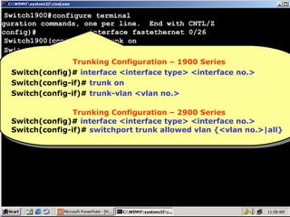


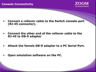
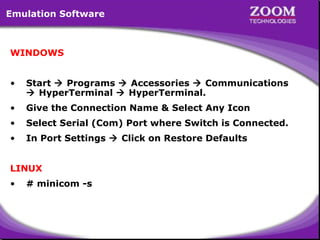
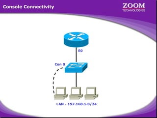
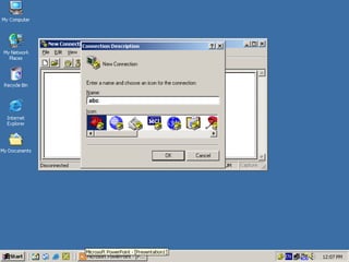
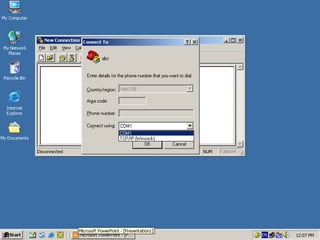
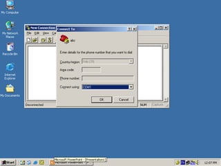
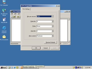
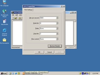
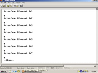
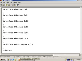
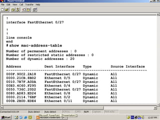
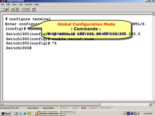
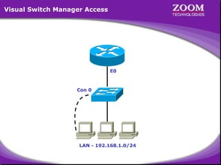
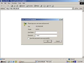
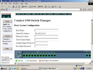
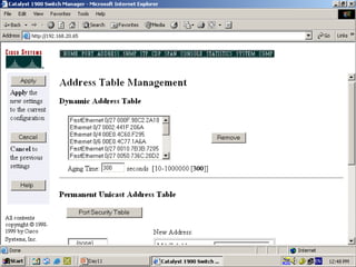
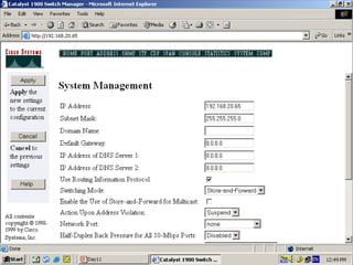
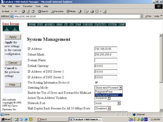
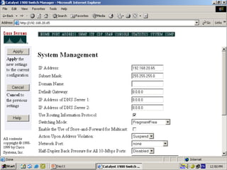
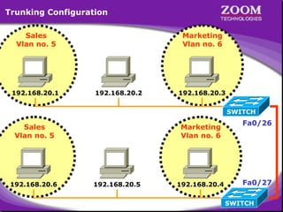
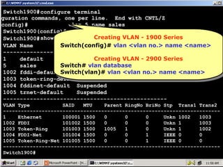
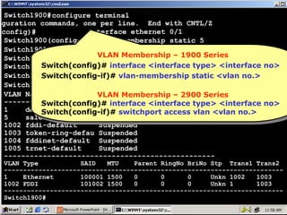
This document provides instructions for connecting to and navigating the management console of a Cisco Catalyst 1900 switch. It includes: 1) Connecting a PC to the switch console port using a rollover cable and serial port adapter. 2) Opening terminal emulation software on the PC like HyperTerminal or Minicom to access the switch console. 3) Browsing the switch management console menu to configure settings like the IP address, subnet mask, and switching various ports to different VLANs for network segmentation.


![Ccna lab manual[1]](https://cdn.slidesharecdn.com/ss_thumbnails/ccnalabmanual1-120706013431-phpapp02-thumbnail.jpg?width=640&height=640&fit=bounds)


