Downloaded 11 times


![© 2002, Cisco Systems, Inc. All rights reserved. ICND v2.0—1-8
Initial Bootup Output
from the Catalyst 2950 Switch
--- System Configuration Dialog ---
At any point you may enter a question mark '?' for help.
Use ctrl-c to abort configuration dialog at any prompt.
Default settings are in square brackets '[ ]'.
Continue with configuration dialog? [yes/no]: yes
Enter IP address: ip_address
Enter IP netmask: ip_netmask
Would you like to enter a default gateway address? [yes]: yes
IP address of the default gateway: ip_address
Enter a host name: host_name
Enter enable secret: secret_password
Would you like to configure a Telnet password? [yes] yes
Enter Telnet password: telnet_password
Would you like to enable as a cluster command switch? no
Enter cluster name: cls_name](https://image.slidesharecdn.com/day13-150514064121-lva1-app6892/85/Day-13-1-startingaswitch-8-320.jpg)


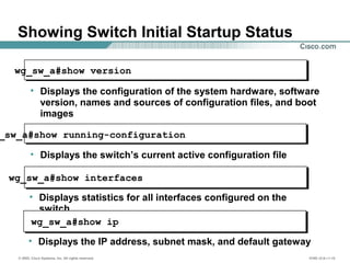


El documento proporciona información sobre cómo iniciar un switch de capa de acceso de Cisco y reconocer la secuencia de arranque normal. Describe el uso de la interfaz de línea de comandos para interactuar con el software IOS de Cisco y cómo utilizar las funciones de ayuda en línea asociadas. Además, se detallan los modos de configuración y los comandos para verificar el estado inicial del switch durante el arranque.