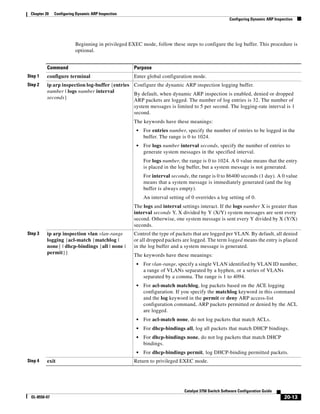
This document provides information about configuring a Cisco Catalyst 2960 switch, including:
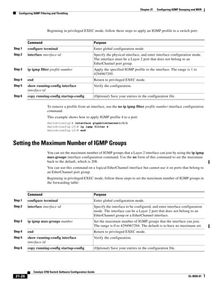
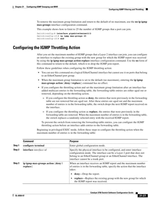
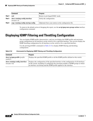
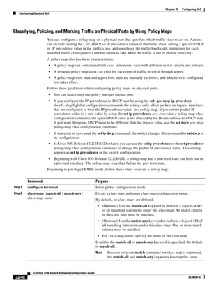
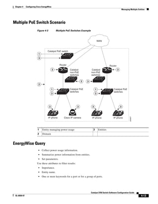
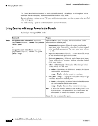
- Details on the Catalyst 2960 switch software configuration guide for Cisco IOS Release 12.2(50)SE.
- Instructions and guidelines for configuring features such as VLANs, security, QoS, monitoring, and more.
- Examples of network configuration designs using Catalyst 2960 switches.
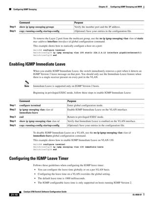
- Information on default settings, commands, and other technical aspects of switch configuration.


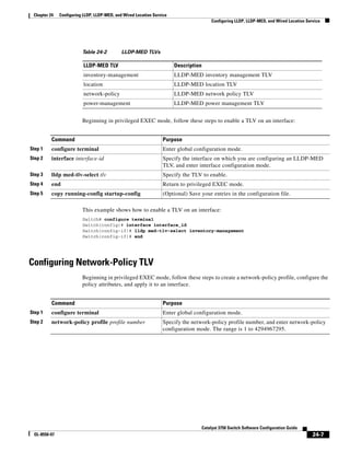
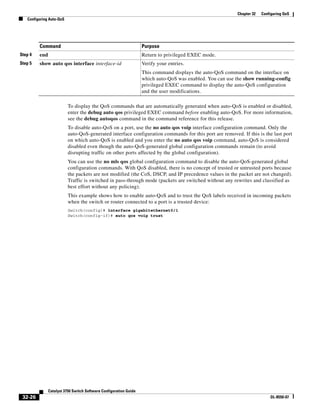
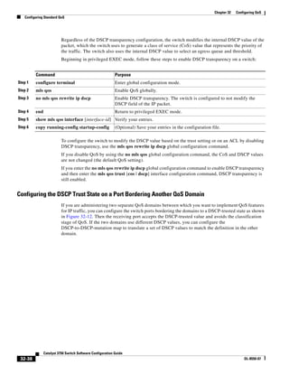
![xxxiv
Catalyst 3750 Switch Software Configuration Guide
OL-8550-07
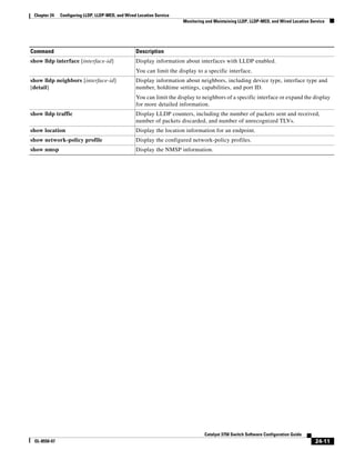
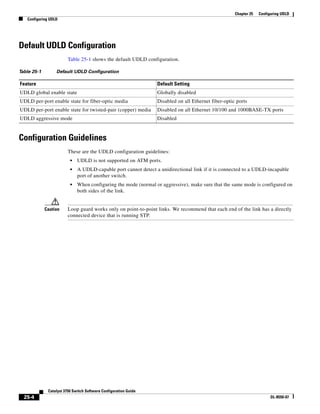
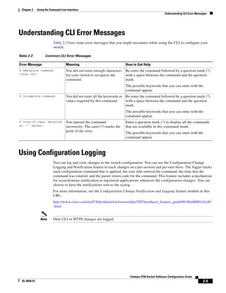
Preface
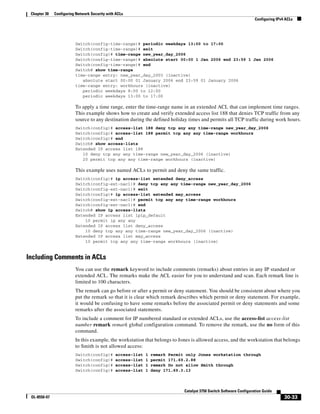
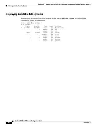
• Square brackets ([ ]) mean optional elements.
• Braces ({ }) group required choices, and vertical bars ( | ) separate the alternative elements.
• Braces and vertical bars within square brackets ([{ | }]) mean a required choice within an optional
element.
Interactive examples use these conventions:
• Terminal sessions and system displays are in screen font.
• Information you enter is in boldface screen font.
• Nonprinting characters, such as passwords or tabs, are in angle brackets (< >).
Notes, cautions, and timesavers use these conventions and symbols:
Note Means reader take note. Notes contain helpful suggestions or references to materials not contained in
this manual.
Caution Means reader be careful. In this situation, you might do something that could result in equipment
damage or loss of data.
Related Publications
These documents provide complete information about the switch and are available from this Cisco.com
site:
http://www.cisco.com/en/US/products/ps6406/tsd_products_support_series_home.html
Note Before installing, configuring, or upgrading the switch, see these documents:
• For initial configuration information, see the “Using Express Setup” section in the getting started
guide or the “Configuring the Switch with the CLI-Based Setup Program” appendix in the hardware
installation guide.
• For device manager requirements, see the “System Requirements” section in the release notes (not
orderable but available on Cisco.com).
• For Network Assistant requirements, see the Getting Started with Cisco Network Assistant (not
orderable but available on Cisco.com).
• For cluster requirements, see the Release Notes for Cisco Network Assistant (not orderable but
available on Cisco.com).
• For upgrading information, see the “Downloading Software” section in the release notes.
See these documents for other information about the switch:
• Release Notes for the Catalyst 3750, 3560, 2970, and 2960 Switches
• Catalyst 3750, 3560, 3550, 2975, 2975, 2970, and 2960 Switch System Message Guide
• Catalyst 2960 Switch Software Configuration Guide
• Catalyst 2960 Switch Command Reference](https://image.slidesharecdn.com/2960scg-150701081942-lva1-app6891/85/Cisco-2960-Switch-Configuration-34-320.jpg)

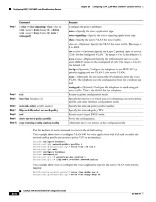
![1-5
Catalyst 3750 Switch Software Configuration Guide
OL-8550-07
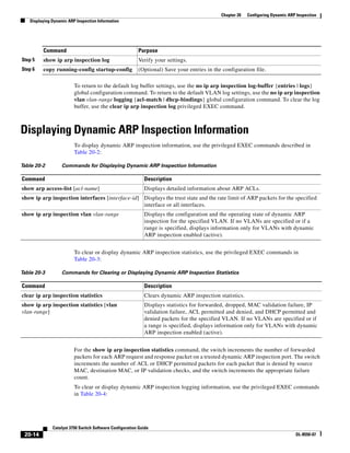
Chapter 1 Overview
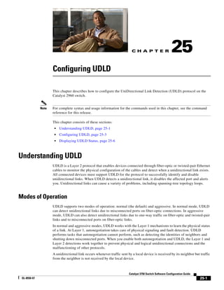
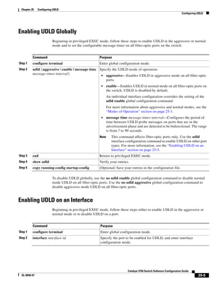
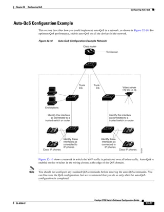
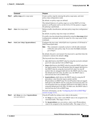
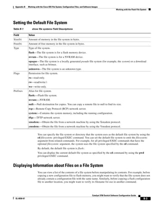
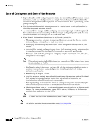
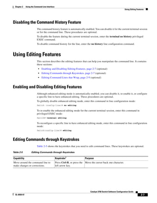
Features
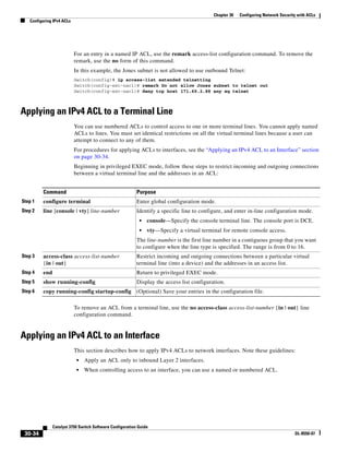
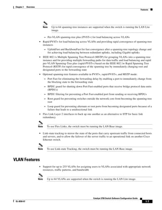
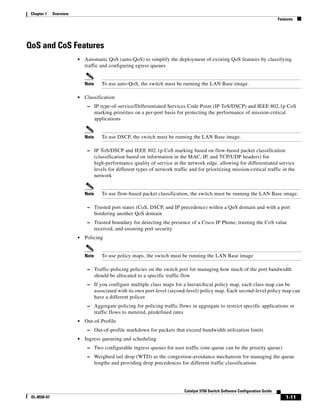
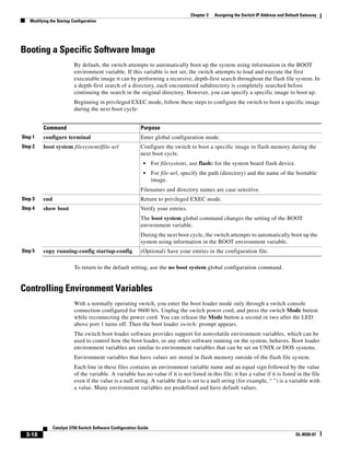
• Cisco IOS Configuration Engine (previously known to as the Cisco IOS CNS
agent)-—Configuration service automates the deployment and management of network devices and
services. You can automate initial configurations and configuration updates by generating
switch-specific configuration changes, sending them to the switch, executing the configuration
change, and logging the results.
For more information about CNS, see Chapter 5, “Configuring Cisco IOS Configuration Engine.”
Manageability Features
• CNS embedded agents for automating switch management, configuration storage, and delivery
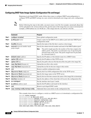
• DHCP for automating configuration of switch information (such as IP address, default gateway,
hostname, and Domain Name System [DNS] and TFTP server names)
• DHCP relay for forwarding User Datagram Protocol (UDP) broadcasts, including IP address
requests, from DHCP clients
• DHCP server for automatic assignment of IP addresses and other DHCP options to IP hosts
• DHCP-based autoconfiguration and image update to download a specified configuration a new
image to a large number of switches
• DHCP server port-based address allocation for the preassignment of an IP address to a switch port
• Directed unicast requests to a DNS server for identifying a switch through its IP address and its
corresponding hostname and to a TFTP server for administering software upgrades from a TFTP
server
• Address Resolution Protocol (ARP) for identifying a switch through its IP address and its
corresponding MAC address
• Unicast MAC address filtering to drop packets with specific source or destination MAC addresses
• Configurable MAC address scaling that allows disabling MAC address learning on a VLAN to limit
the size of the MAC address table
• Cisco Discovery Protocol (CDP) Versions 1 and 2 for network topology discovery and mapping
between the switch and other Cisco devices on the network
• Link Layer Discovery Protocol (LLDP) and LLDP Media Endpoint Discovery (LLDP-MED) for
interoperability with third-party IP phones
• LLDP media extensions (LLDP-MED) location TLV that provides location information from the
switch to the endpoint device
Note To use LLDP-MED, the switch must be running the LAN Base image.
• Network Time Protocol (NTP) for providing a consistent time stamp to all switches from an external
source
• Cisco IOS File System (IFS) for providing a single interface to all file systems that the switch uses
• Support for the SSM PIM protocol to optimize multicast applications, such as video
• Source Specific Multicast (SSM) mapping for multicast applications provides a mapping of source
to group, allowing listeners to connect to multicast sources dynamically and reduces dependencies
on the application
• Support for Enhanced Interior Gateway Routing Protocol (EIGRP) IPv6 to utilize IPv6 transport,
communicate with IPv6 peers, and advertise IPv6 routes](https://image.slidesharecdn.com/2960scg-150701081942-lva1-app6891/85/Cisco-2960-Switch-Configuration-41-320.jpg)

![2-6
Catalyst 3750 Switch Software Configuration Guide
OL-8550-07
Chapter 2 Using the Command-Line Interface
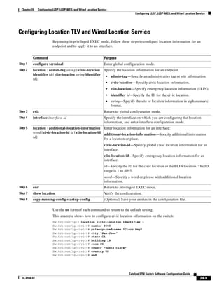
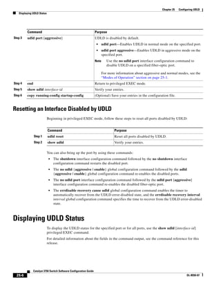
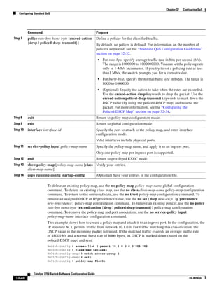
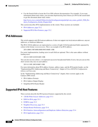
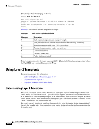
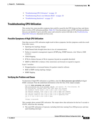
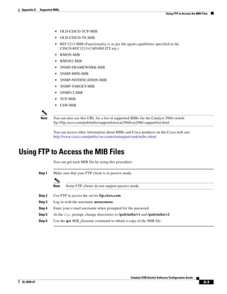
Using Command History
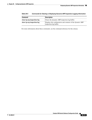
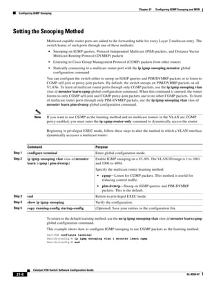
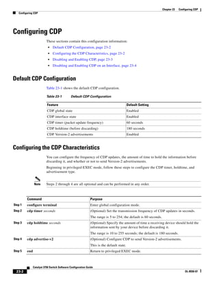
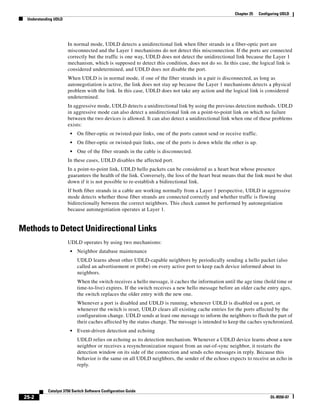
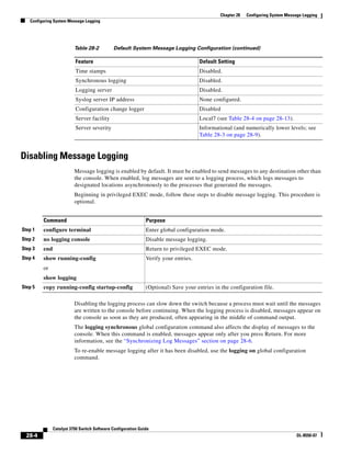
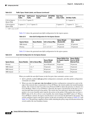
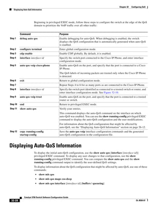
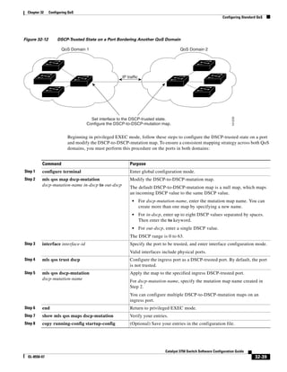
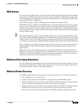
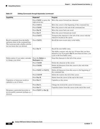
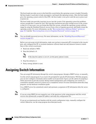
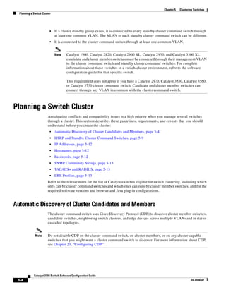
Using Command History
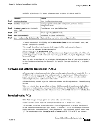
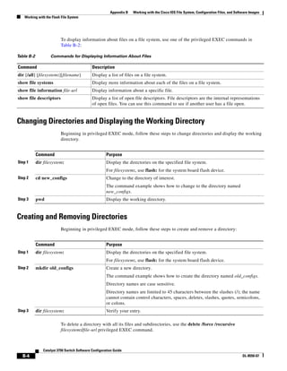
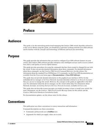
The software provides a history or record of commands that you have entered. The command history
feature is particularly useful for recalling long or complex commands or entries, including access lists.
You can customize this feature to suit your needs as described in these sections:
• Changing the Command History Buffer Size, page 2-6 (optional)
• Recalling Commands, page 2-6 (optional)
• Disabling the Command History Feature, page 2-7 (optional)
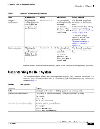
Changing the Command History Buffer Size
By default, the switch records ten command lines in its history buffer. You can alter this number for a
current terminal session or for all sessions on a particular line. These procedures are optional.
Beginning in privileged EXEC mode, enter this command to change the number of command lines that
the switch records during the current terminal session:
Switch# terminal history [size number-of-lines]
The range is from 0 to 256.
Beginning in line configuration mode, enter this command to configure the number of command lines
the switch records for all sessions on a particular line:
Switch(config-line)# history [size number-of-lines]
The range is from 0 to 256.
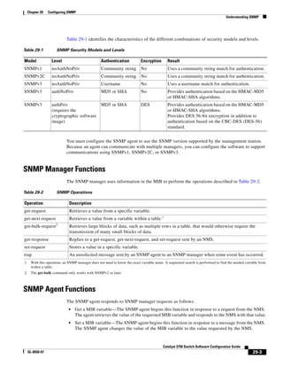
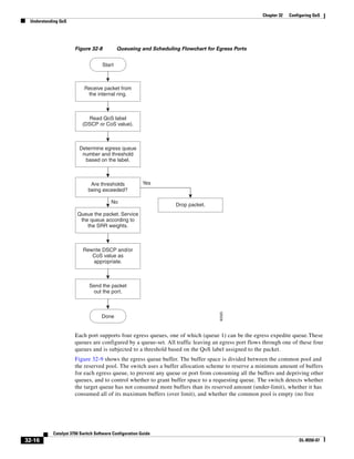
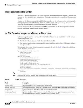
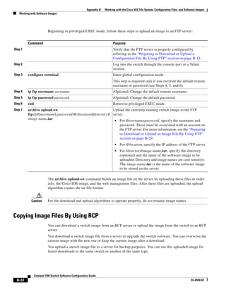
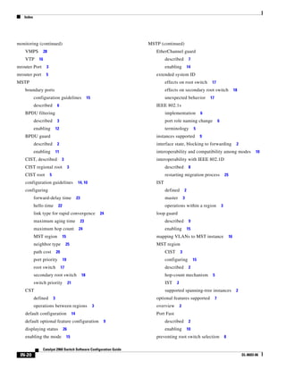
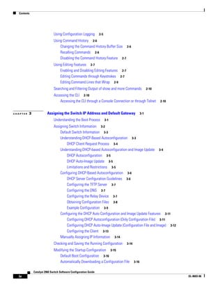
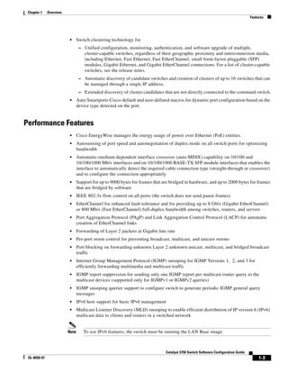
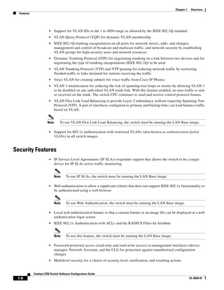
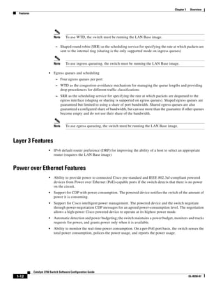
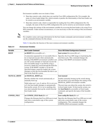
Recalling Commands
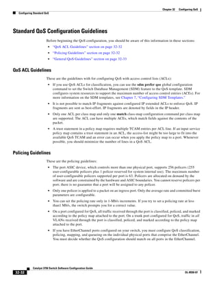
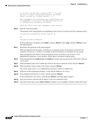
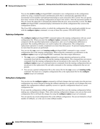
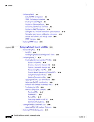
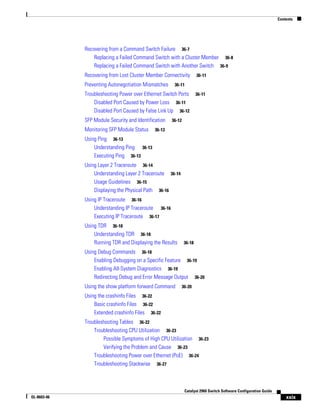
To recall commands from the history buffer, perform one of the actions listed in Table 2-4. These actions
are optional.
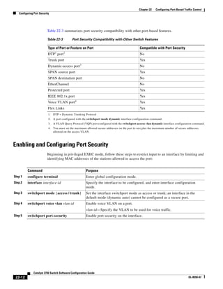
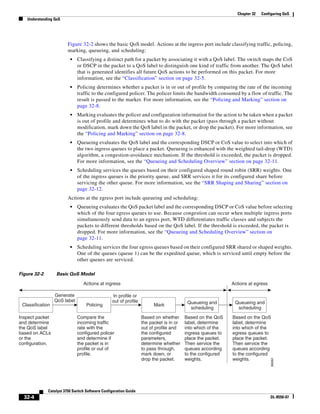
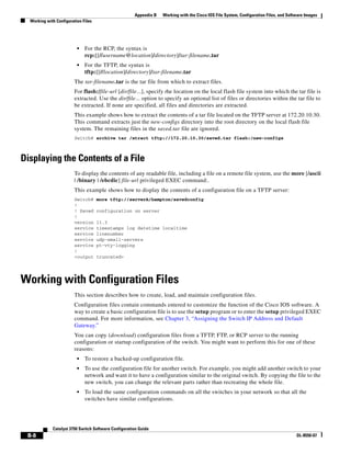
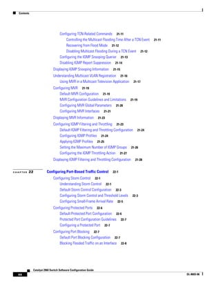
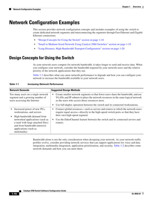
Table 2-4 Recalling Commands
Action1
1. The arrow keys function only on ANSI-compatible terminals such as VT100s.
Result
Press Ctrl-P or the up arrow key. Recall commands in the history buffer, beginning with the most recent command.
Repeat the key sequence to recall successively older commands.
Press Ctrl-N or the down arrow key. Return to more recent commands in the history buffer after recalling commands
with Ctrl-P or the up arrow key. Repeat the key sequence to recall successively
more recent commands.
show history While in privileged EXEC mode, list the last several commands that you just
entered. The number of commands that appear is controlled by the setting of the
terminal history global configuration command and the history line configuration
command.](https://image.slidesharecdn.com/2960scg-150701081942-lva1-app6891/85/Cisco-2960-Switch-Configuration-64-320.jpg)
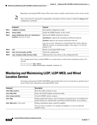
![3-15
Catalyst 3750 Switch Software Configuration Guide
OL-8550-07
Chapter 3 Assigning the Switch IP Address and Default Gateway
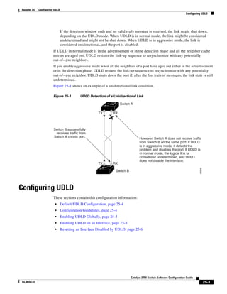
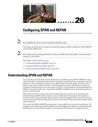
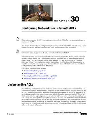
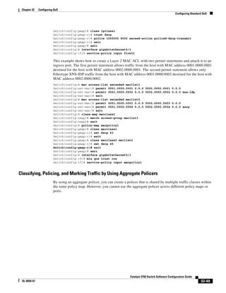
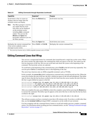
Modifying the Startup Configuration
no service pad
service timestamps debug uptime
service timestamps log uptime
no service password-encryption
!
hostname Switch A
!
enable secret 5 $1$ej9.$DMUvAUnZOAmvmgqBEzIxE0
!
.
<output truncated>
.
interface gigabitethernet0/1
ip address 172.20.137.50 255.255.255.0
!
interface gigabitethernet0/2
mvr type source
<output truncated>
...!
interface VLAN1
ip address 172.20.137.50 255.255.255.0
no ip directed-broadcast
!
ip default-gateway 172.20.137.1 !
!
snmp-server community private RW
snmp-server community public RO
snmp-server community private@es0 RW
snmp-server community public@es0 RO
snmp-server chassis-id 0x12
!
end
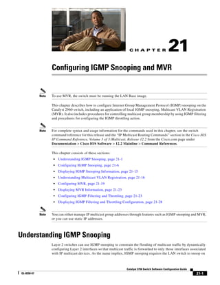
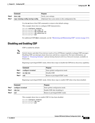
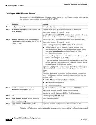
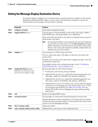
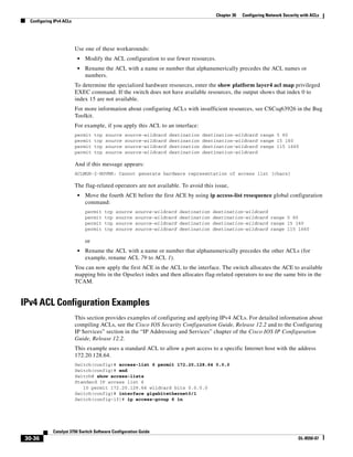
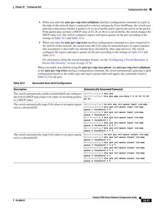
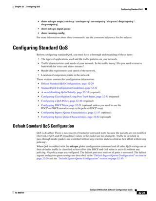
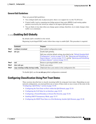
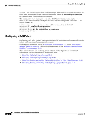
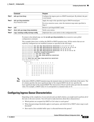
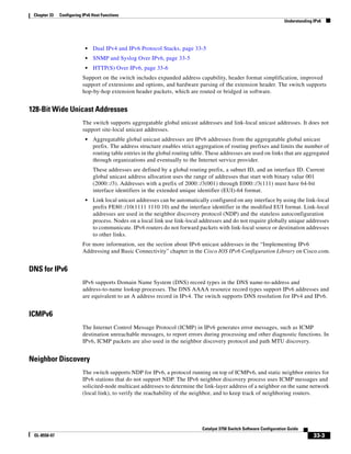
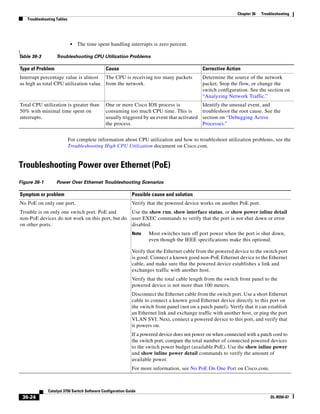
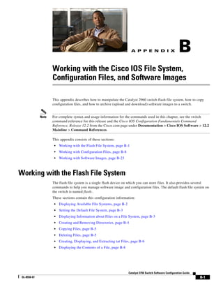
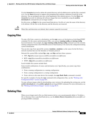
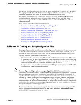
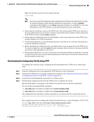
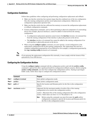
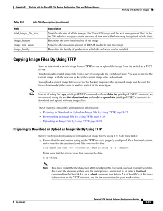
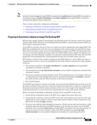
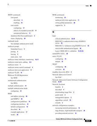
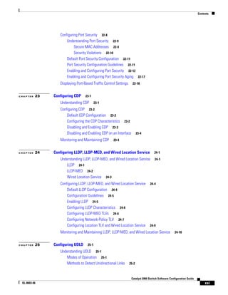
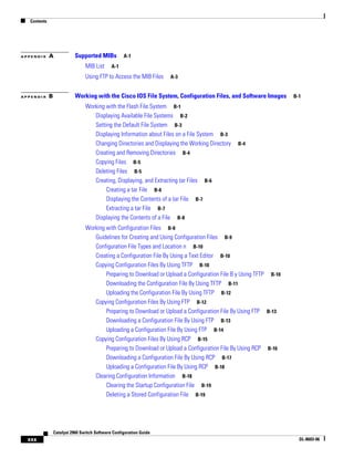
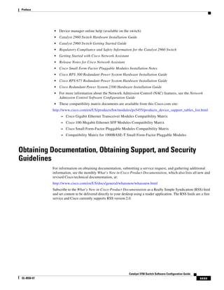
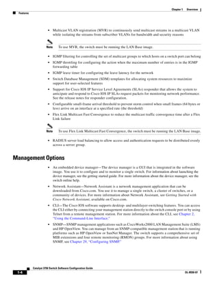
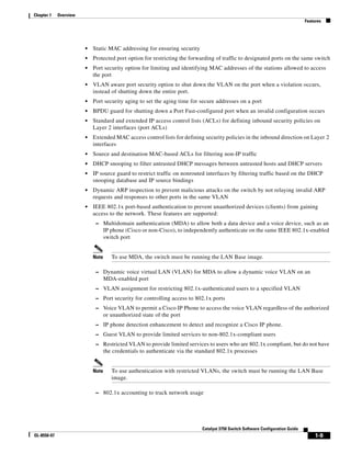
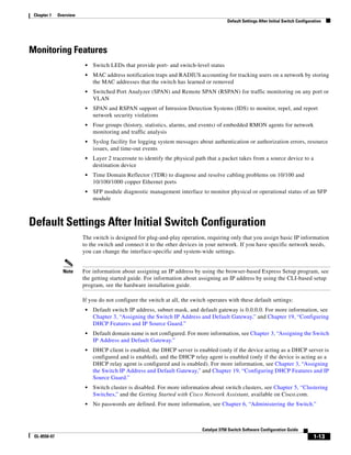
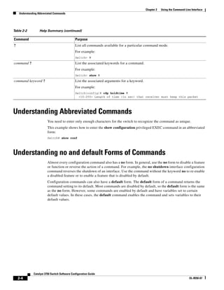
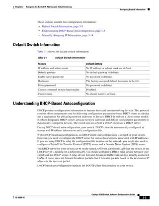
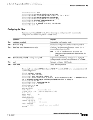
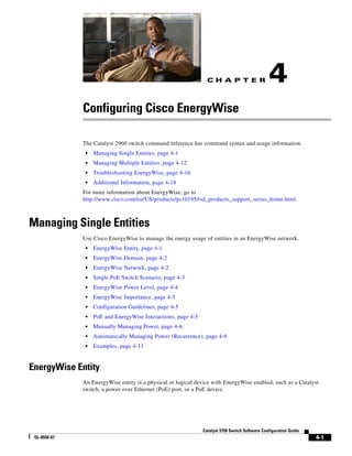
To store the configuration or changes you have made to your startup configuration in flash memory,
enter this privileged EXEC command:
Switch# copy running-config startup-config
Destination filename [startup-config]?
Building configuration...
This command saves the configuration settings that you made. If you fail to do this, your configuration
will be lost the next time you reload the system. To display information stored in the NVRAM section
of flash memory, use the show startup-config or more startup-config privileged EXEC command.
For more information about alternative locations from which to copy the configuration file, see
Appendix B, “Working with the Cisco IOS File System, Configuration Files, and Software Images.”
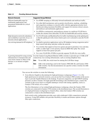
Modifying the Startup Configuration
These sections describe how to modify the switch startup configuration:
• Default Boot Configuration, page 3-16
• Automatically Downloading a Configuration File, page 3-16
• Booting Manually, page 3-17
• Booting a Specific Software Image, page 3-18
• Controlling Environment Variables, page 3-18](https://image.slidesharecdn.com/2960scg-150701081942-lva1-app6891/85/Cisco-2960-Switch-Configuration-83-320.jpg)
![3-20
Catalyst 3750 Switch Software Configuration Guide
OL-8550-07
Chapter 3 Assigning the Switch IP Address and Default Gateway
Scheduling a Reload of the Software Image
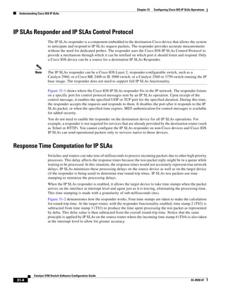
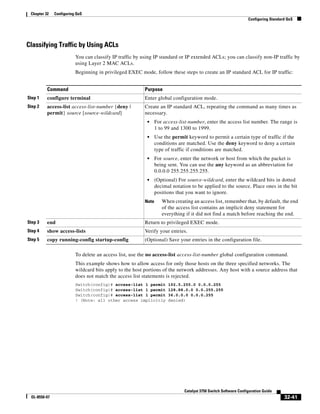
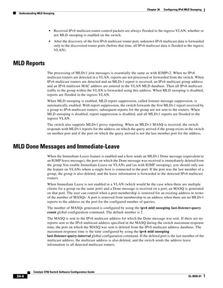
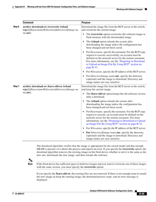
Scheduling a Reload of the Software Image
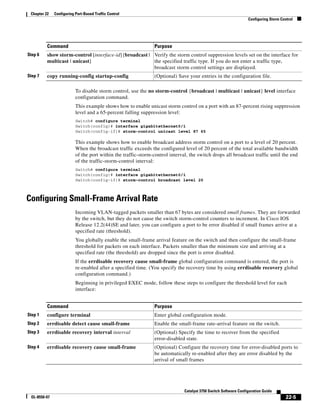
You can schedule a reload of the software image to occur on the switch at a later time (for example, late
at night or during the weekend when the switch is used less), or you can synchronize a reload
network-wide (for example, to perform a software upgrade on all switches in the network).
Note A scheduled reload must take place within approximately 24 days.
Configuring a Scheduled Reload
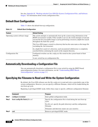
To configure your switch to reload the software image at a later time, use one of these commands in
privileged EXEC mode:
• reload in [hh:]mm [text]
This command schedules a reload of the software to take affect in the specified minutes or hours and
minutes. The reload must take place within approximately 24 days. You can specify the reason for
the reload in a string up to 255 characters in length.
• reload at hh:mm [month day | day month] [text]
This command schedules a reload of the software to take place at the specified time (using a 24-hour
clock). If you specify the month and day, the reload is scheduled to take place at the specified time
and date. If you do not specify the month and day, the reload takes place at the specified time on the
current day (if the specified time is later than the current time) or on the next day (if the specified
time is earlier than the current time). Specifying 00:00 schedules the reload for midnight.
Note Use the at keyword only if the switch system clock has been set (through Network Time
Protocol (NTP), the hardware calendar, or manually). The time is relative to the configured
time zone on the switch. To schedule reloads across several switches to occur
simultaneously, the time on each switch must be synchronized with NTP.
The reload command halts the system. If the system is not set to manually boot up, it reboots itself. Use
the reload command after you save the switch configuration information to the startup configuration
(copy running-config startup-config).
If your switch is configured for manual booting, do not reload it from a virtual terminal. This restriction
prevents the switch from entering the boot loader mode and thereby taking it from the remote user’s
control.
If you modify your configuration file, the switch prompts you to save the configuration before reloading.
During the save operation, the system requests whether you want to proceed with the save if the
CONFIG_FILE environment variable points to a startup configuration file that no longer exists. If you
proceed in this situation, the system enters setup mode upon reload.
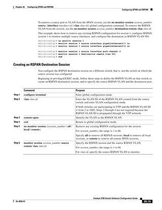
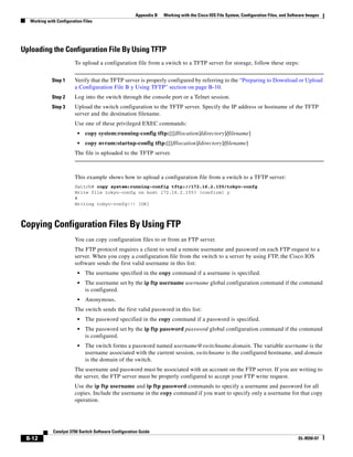
This example shows how to reload the software on the switch on the current day at 7:30 p.m:
Switch# reload at 19:30
Reload scheduled for 19:30:00 UTC Wed Jun 5 1996 (in 2 hours and 25 minutes)
Proceed with reload? [confirm]
This example shows how to reload the software on the switch at a future time:
Switch# reload at 02:00 jun 20
Reload scheduled for 02:00:00 UTC Thu Jun 20 1996 (in 344 hours and 53 minutes)](https://image.slidesharecdn.com/2960scg-150701081942-lva1-app6891/85/Cisco-2960-Switch-Configuration-88-320.jpg)
![3-21
Catalyst 3750 Switch Software Configuration Guide
OL-8550-07
Chapter 3 Assigning the Switch IP Address and Default Gateway
Scheduling a Reload of the Software Image
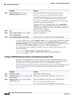
Proceed with reload? [confirm]
To cancel a previously scheduled reload, use the reload cancel privileged EXEC command.
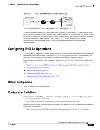
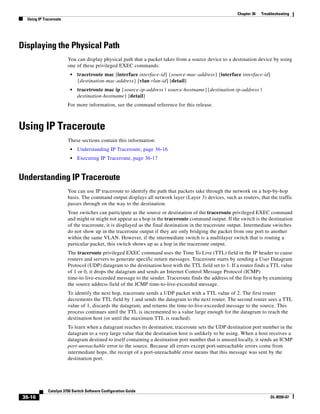
Displaying Scheduled Reload Information
To display information about a previously scheduled reload or to find out if a reload has been scheduled
on the switch, use the show reload privileged EXEC command.
It displays reload information including the time the reload is scheduled to occur and the reason for the
reload (if it was specified when the reload was scheduled).](https://image.slidesharecdn.com/2960scg-150701081942-lva1-app6891/85/Cisco-2960-Switch-Configuration-89-320.jpg)

![4-6
Catalyst 3750 Switch Software Configuration Guide
OL-8550-07
Chapter 4 Configuring Cisco EnergyWise
Managing Single Entities
Manually Managing Power
• Powering the Entity, page 4-6
• Configuring Entity Attributes, page 4-7
• Powering the PoE Port, page 4-8
• Configuring PoE-Port Attributes, page 4-8
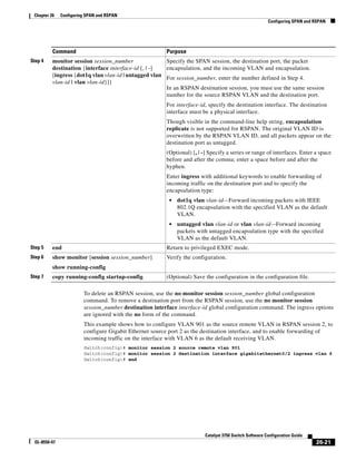
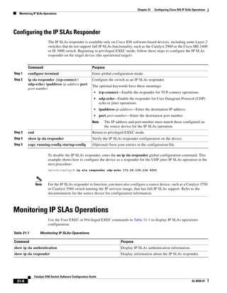
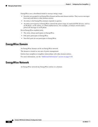
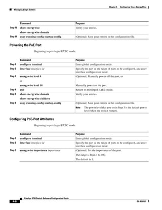
Powering the Entity
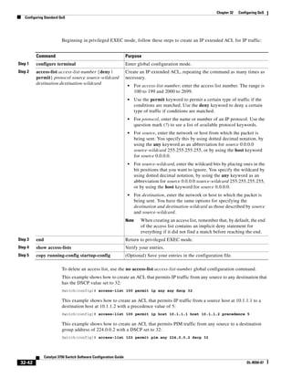
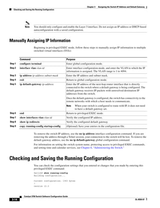
Beginning in privileged EXEC mode:
Command Purpose
Step 1 show energywise (Optional) Verify that EnergyWise is disabled.
Step 2 configure terminal Enter global configuration mode.
Step 3 energywise domain domain-name secret [0 | 7]
password [protocol udp port udp-port-number
[interface interface-id | ip ip-address]]
Enable EnergyWise on the entity, assign the entity to a domain
with the specified domain-name, and set the password for secure
communication among the entities in the domain.
• (Optional) 0—Use an unencrypted password. This is the
default.
• (Optional) 7—Use a hidden password.
If you do not enter 0 or 7, the entity uses the default value of
0.
• (Optional) port udp-port-number—Specify the UDP port
that sends and receives queries.
The range is from 1 to 65000. The default is 43440.
• (Optional) interface interface-id—Specify the port from
which the EnergyWise messages are sent.
• (Optional) ip ip-address—Specify the IP address from which
the EnergyWise messages are sent.
For the domain-name and password
• You can enter alphanumeric characters and symbols such as
#, (, %, !, or &.
• Do not use an asterisk (*) or a blank space between the
characters and symbols.
By default, no domain and password are assigned.
Step 4 end Return to privileged EXEC mode.
Step 5 show energywise
show energywise domain
Verify your entries.
Step 6 copy running-config startup-config (Optional) Save your entries in the configuration file.](https://image.slidesharecdn.com/2960scg-150701081942-lva1-app6891/85/Cisco-2960-Switch-Configuration-96-320.jpg)
![4-7
Catalyst 3750 Switch Software Configuration Guide
OL-8550-07
Chapter 4 Configuring Cisco EnergyWise
Managing Single Entities
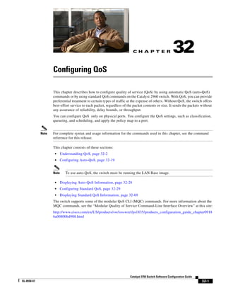
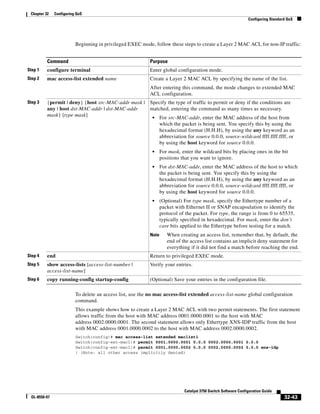
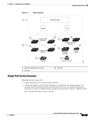
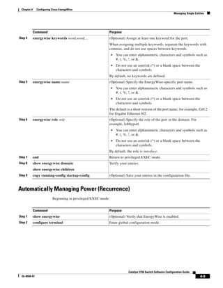
Configuring Entity Attributes
Beginning in privileged EXEC mode:
Command Purpose
Step 1 show energywise (Optional) Verify that EnergyWise is enabled.
Step 2 configure terminal Enter global configuration mode.
Step 3 energywise importance importance (Optional) Set the importance of the entity.
The range is from 1 to 100.
The default is 1.
Step 4 energywise keywords word,word,... (Optional) Assign at least one keyword for the entity.
When assigning multiple keywords, separate the keywords with
commas, and do not use spaces between keywords.
• You can enter alphanumeric characters and symbols such as
#, (, %, !, or &.
• Do not use an asterisk (*) or a blank space between the
characters and symbols.
By default, no keywords are defined.
Step 5 energywise management udp-port-number (Optional) Specify the UDP port that sends and receives queries.
The range is from 1 to 65000.
The default is 43440.
Step 6 energywise name name (Optional) Specify the EnergyWise-specific entity name.
• You can enter alphanumeric characters and symbols such as
#, (, %, !, or &.
• Do not use an asterisk (*) or a blank space between the
characters and symbols.
The default is the hostname.
Step 7 energywise neighbor [hostname| ip-address]
udp-port-number
(Optional) Assign a static neighbor.
• (Optional) Hostname (hostname) or IP address (ip-address).
• UDP port (udp-port-number) that sends and receives queries.
The range is from 1 to 65000.
By default, no static neighbors are assigned.
Step 8 energywise role role (Optional) Specify the role of the entity in the EnergyWise
domain. For example, lobby.b20.
• You can enter alphanumeric characters and symbols such as
#, (, %, !, or &.
• Do not use an asterisk (*) or a blank space between the
characters and symbols.
The default is the model number.
Step 9 end Return to privileged EXEC mode.](https://image.slidesharecdn.com/2960scg-150701081942-lva1-app6891/85/Cisco-2960-Switch-Configuration-97-320.jpg)
![4-10
Catalyst 3750 Switch Software Configuration Guide
OL-8550-07
Chapter 4 Configuring Cisco EnergyWise
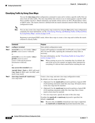
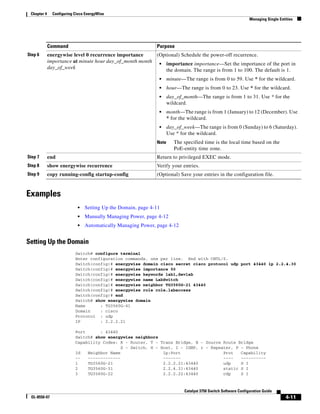
Managing Single Entities
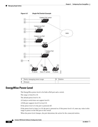
Step 3 energywise domain domain-name secret [0 | 7]
password [protocol udp port udp-port-number
[interface interface-id | ip ip-address]]
Enable EnergyWise on the entity, assign the entity to a domain
with the specified domain-name, and set the password for secure
communication among the entities in the domain.
• (Optional) 0—Use an unencrypted password. This is the
default.
• (Optional) 7—Use a hidden password.
If you do not enter 0 or 7, the entity uses the default value of
0.
• (Optional) port udp-port-number—Specify the UDP port
that sends and receives queries.
The range is from 1 to 65000.
The default is 43440.
• (Optional) interface interface-id—Specify the port that
sends EnergyWise messages.
• (Optional) ip ip-address—Specify the IP address of the port
that sends EnergyWise messages.
For the domain-name and password,
• You can enter alphanumeric characters and symbols such as
#, (, %, !, or &.
• Do not use an asterisk (*) or a blank space between the
characters and symbols.
By default, no domain and password are assigned.
Step 4 interface interface-id Specify the port or a range of ports to be configured, and enter
interface configuration mode.
Step 5 energywise level 10 recurrence importance
importance at minute hour day_of_month month
day_of_week
(Optional) Schedule the power-on recurrence.
• importance importance—Set the importance of the port in
the domain. The range is from 1 to 100. The default is 1.
• minute—The range is from 0 to 59. Use * for the wildcard.
• hour—The range is from 0 to 23. Use * for the wildcard.
• day_of_month—The range is from 1 to 31. Use * for the
wildcard.
• month—The range is from 1 (January) to 12 (December). Use
* for the wildcard.
• day_of_week—The range is from 0 (Sunday) to 6 (Saturday).
Use * for the wildcard.
Note The specified time is the local time based on the
PoE-entity time zone.
Command Purpose](https://image.slidesharecdn.com/2960scg-150701081942-lva1-app6891/85/Cisco-2960-Switch-Configuration-100-320.jpg)
![4-20
Catalyst 3750 Switch Software Configuration Guide
OL-8550-07
Chapter 4 Configuring Cisco EnergyWise
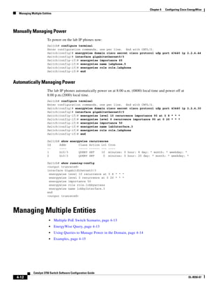
Additional Information
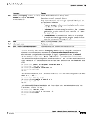
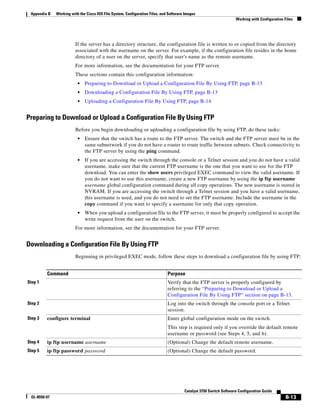
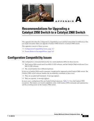
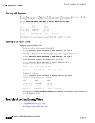
Note To prevent a disjointed domain, you can also configure a helper address on Router A and specify that the
router use UDP to forward broadcast packets with the
ip helper-address address interface configuration command.
ip forward-protocol udp [port] global configuration command.](https://image.slidesharecdn.com/2960scg-150701081942-lva1-app6891/85/Cisco-2960-Switch-Configuration-110-320.jpg)

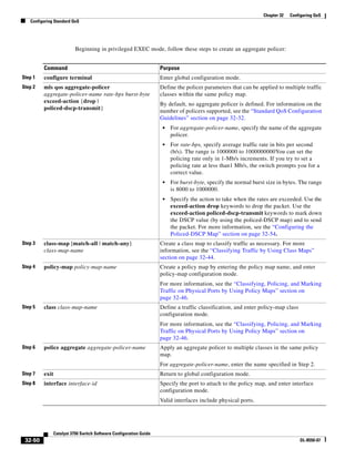
![6-6
Catalyst 3750 Switch Software Configuration Guide
OL-8550-07
Chapter 6 Administering the Switch
Managing the System Time and Date
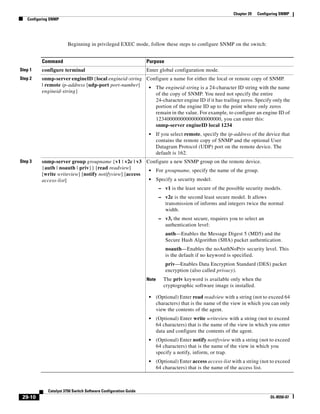
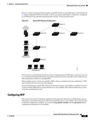
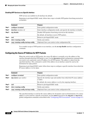
Beginning in privileged EXEC mode, follow these steps to form an NTP association with another device:
You need to configure only one end of an association; the other device can automatically establish the
association. If you are using the default NTP version (Version 3) and NTP synchronization does not
occur, try using NTP Version 2. Many NTP servers on the Internet run Version 2.
To remove a peer or server association, use the no ntp peer ip-address or the no ntp server ip-address
global configuration command.
This example shows how to configure the switch to synchronize its system clock with the clock of the
peer at IP address 172.16.22.44 using NTP Version 2:
Switch(config)# ntp server 172.16.22.44 version 2
Configuring NTP Broadcast Service
The communications between devices running NTP (known as associations) are usually statically
configured; each device is given the IP addresses of all devices with which it should form associations.
Accurate timekeeping is possible by exchanging NTP messages between each pair of devices with an
association. However, in a LAN environment, NTP can be configured to use IP broadcast messages
instead. This alternative reduces configuration complexity because each device can simply be
configured to send or receive broadcast messages. However, the information flow is one-way only.
Command Purpose
Step 1 configure terminal Enter global configuration mode.
Step 2 ntp peer ip-address [version number]
[key keyid] [source interface] [prefer]
or
ntp server ip-address [version number]
[key keyid] [source interface] [prefer]
Configure the switch system clock to synchronize a peer or to be
synchronized by a peer (peer association).
or
Configure the switch system clock to be synchronized by a time server
(server association).
No peer or server associations are defined by default.
• For ip-address in a peer association, specify either the IP address of
the peer providing, or being provided, the clock synchronization. For
a server association, specify the IP address of the time server
providing the clock synchronization.
• (Optional) For number, specify the NTP version number. The range
is 1 to 3. By default, Version 3 is selected.
• (Optional) For keyid, enter the authentication key defined with the
ntp authentication-key global configuration command.
• (Optional) For interface, specify the interface from which to pick the
IP source address. By default, the source IP address is taken from the
outgoing interface.
• (Optional) Enter the prefer keyword to make this peer or server the
preferred one that provides synchronization. This keyword reduces
switching back and forth between peers and servers.
Step 3 end Return to privileged EXEC mode.
Step 4 show running-config Verify your entries.
Step 5 copy running-config startup-config (Optional) Save your entries in the configuration file.](https://image.slidesharecdn.com/2960scg-150701081942-lva1-app6891/85/Cisco-2960-Switch-Configuration-132-320.jpg)
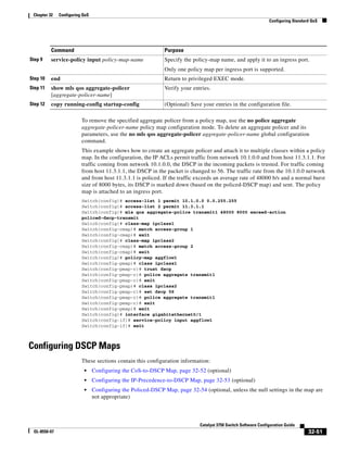
![6-7
Catalyst 3750 Switch Software Configuration Guide
OL-8550-07
Chapter 6 Administering the Switch
Managing the System Time and Date
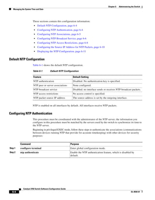
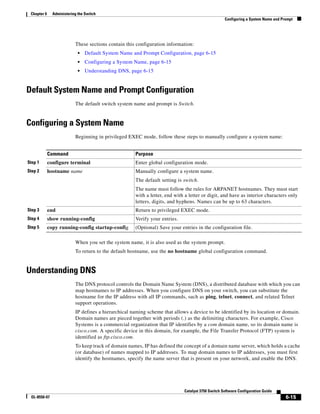
The switch can send or receive NTP broadcast packets on an interface-by-interface basis if there is an
NTP broadcast server, such as a router, broadcasting time information on the network. The switch can
send NTP broadcast packets to a peer so that the peer can synchronize to it. The switch can also receive
NTP broadcast packets to synchronize its own clock. This section provides procedures for both sending
and receiving NTP broadcast packets.
Beginning in privileged EXEC mode, follow these steps to configure the switch to send NTP broadcast
packets to peers so that they can synchronize their clock to the switch:
To disable the interface from sending NTP broadcast packets, use the no ntp broadcast interface
configuration command.
This example shows how to configure a port to send NTP Version 2 packets:
Switch(config)# interface gigabitethernet0/1
Switch(config-if)# ntp broadcast version 2
Beginning in privileged EXEC mode, follow these steps to configure the switch to receive NTP
broadcast packets from connected peers:
Command Purpose
Step 1 configure terminal Enter global configuration mode.
Step 2 interface interface-id Specify the interface to send NTP broadcast packets, and enter
interface configuration mode.
Step 3 ntp broadcast [version number] [key keyid]
[destination-address]
Enable the interface to send NTP broadcast packets to a peer.
By default, this feature is disabled on all interfaces.
• (Optional) For number, specify the NTP version number. The
range is 1 to 3. If you do not specify a version, Version 3 is used.
• (Optional) For keyid, specify the authentication key to use when
sending packets to the peer.
• (Optional) For destination-address, specify the IP address of the
peer that is synchronizing its clock to this switch.
Step 4 end Return to privileged EXEC mode.
Step 5 show running-config Verify your entries.
Step 6 copy running-config startup-config (Optional) Save your entries in the configuration file.
Step 7 Configure the connected peers to receive NTP broadcast packets as
described in the next procedure.
Command Purpose
Step 1 configure terminal Enter global configuration mode.
Step 2 interface interface-id Specify the interface to receive NTP broadcast packets, and enter
interface configuration mode.
Step 3 ntp broadcast client Enable the interface to receive NTP broadcast packets.
By default, no interfaces receive NTP broadcast packets.
Step 4 exit Return to global configuration mode.](https://image.slidesharecdn.com/2960scg-150701081942-lva1-app6891/85/Cisco-2960-Switch-Configuration-133-320.jpg)
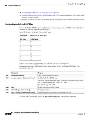
![6-9
Catalyst 3750 Switch Software Configuration Guide
OL-8550-07
Chapter 6 Administering the Switch
Managing the System Time and Date
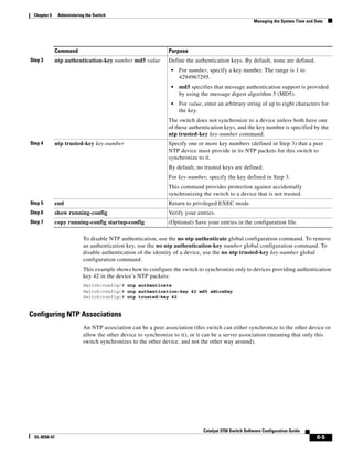
The access group keywords are scanned in this order, from least restrictive to most restrictive:
1. peer—Allows time requests and NTP control queries and allows the switch to synchronize itself to
a device whose address passes the access list criteria.
2. serve—Allows time requests and NTP control queries, but does not allow the switch to synchronize
itself to a device whose address passes the access list criteria.
3. serve-only—Allows only time requests from a device whose address passes the access list criteria.
4. query-only—Allows only NTP control queries from a device whose address passes the access list
criteria.
If the source IP address matches the access lists for more than one access type, the first type is granted.
If no access groups are specified, all access types are granted to all devices. If any access groups are
specified, only the specified access types are granted.
To remove access control to the switch NTP services, use the no ntp access-group {query-only |
serve-only | serve | peer} global configuration command.
This example shows how to configure the switch to allow itself to synchronize to a peer from access
list 99. However, the switch restricts access to allow only time requests from access list 42:
Switch# configure terminal
Switch(config)# ntp access-group peer 99
Switch(config)# ntp access-group serve-only 42
Switch(config)# access-list 99 permit 172.20.130.5
Switch(config)# access list 42 permit 172.20.130.6
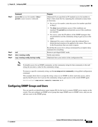
Step 3 access-list access-list-number permit
source [source-wildcard]
Create the access list.
• For access-list-number, enter the number specified in Step 2.
• Enter the permit keyword to permit access if the conditions are
matched.
• For source, enter the IP address of the device that is permitted access
to the switch.
• (Optional) For source-wildcard, enter the wildcard bits to be applied
to the source.
Note When creating an access list, remember that, by default, the end
of the access list contains an implicit deny statement for
everything if it did not find a match before reaching the end.
Step 4 end Return to privileged EXEC mode.
Step 5 show running-config Verify your entries.
Step 6 copy running-config startup-config (Optional) Save your entries in the configuration file.
Command Purpose](https://image.slidesharecdn.com/2960scg-150701081942-lva1-app6891/85/Cisco-2960-Switch-Configuration-135-320.jpg)
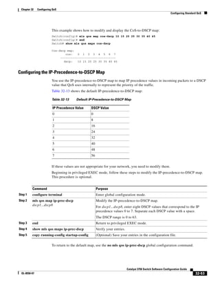
![6-11
Catalyst 3750 Switch Software Configuration Guide
OL-8550-07
Chapter 6 Administering the Switch
Managing the System Time and Date
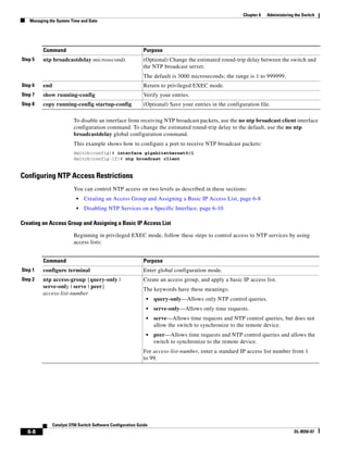
Displaying the NTP Configuration
You can use two privileged EXEC commands to display NTP information:
• show ntp associations [detail]
• show ntp status
Note For detailed information about the fields in these displays, see the Cisco IOS Configuration
Fundamentals Command Reference, Release 12.2 from the Cisco.com page under Documentation >
Cisco IOS Software > 12.2 Mainline > Command References.
Configuring Time and Date Manually
If no other source of time is available, you can manually configure the time and date after the system is
restarted. The time remains accurate until the next system restart. We recommend that you use manual
configuration only as a last resort. If you have an outside source to which the switch can synchronize,
you do not need to manually set the system clock.
These sections contain this configuration information:
• Setting the System Clock, page 6-11
• Displaying the Time and Date Configuration, page 6-12
• Configuring the Time Zone, page 6-12
• Configuring Summer Time (Daylight Saving Time), page 6-13
Setting the System Clock
If you have an outside source on the network that provides time services, such as an NTP server, you do
not need to manually set the system clock.
Beginning in privileged EXEC mode, follow these steps to set the system clock:
This example shows how to manually set the system clock to 1:32 p.m. on July 23, 2001:
Switch# clock set 13:32:00 23 July 2001
Command Purpose
Step 1 clock set hh:mm:ss day month year
or
clock set hh:mm:ss month day year
Manually set the system clock using one of these formats.
• For hh:mm:ss, specify the time in hours (24-hour format), minutes,
and seconds. The time specified is relative to the configured time
zone.
• For day, specify the day by date in the month.
• For month, specify the month by name.
• For year, specify the year (no abbreviation).](https://image.slidesharecdn.com/2960scg-150701081942-lva1-app6891/85/Cisco-2960-Switch-Configuration-137-320.jpg)
![6-12
Catalyst 3750 Switch Software Configuration Guide
OL-8550-07
Chapter 6 Administering the Switch
Managing the System Time and Date
Displaying the Time and Date Configuration
To display the time and date configuration, use the show clock [detail] privileged EXEC command.
The system clock keeps an authoritative flag that shows whether the time is authoritative (believed to be
accurate). If the system clock has been set by a timing source such as NTP, the flag is set. If the time is
not authoritative, it is used only for display purposes. Until the clock is authoritative and the
authoritative flag is set, the flag prevents peers from synchronizing to the clock when the peers’ time is
invalid.
The symbol that precedes the show clock display has this meaning:
• *—Time is not authoritative.
• (blank)—Time is authoritative.
• .—Time is authoritative, but NTP is not synchronized.
Configuring the Time Zone
Beginning in privileged EXEC mode, follow these steps to manually configure the time zone:
The minutes-offset variable in the clock timezone global configuration command is available for those
cases where a local time zone is a percentage of an hour different from UTC. For example, the time zone
for some sections of Atlantic Canada (AST) is UTC-3.5, where the 3 means 3 hours and .5 means 50
percent. In this case, the necessary command is clock timezone AST -3 30.
To set the time to UTC, use the no clock timezone global configuration command.
Command Purpose
Step 1 configure terminal Enter global configuration mode.
Step 2 clock timezone zone hours-offset
[minutes-offset]
Set the time zone.
The switch keeps internal time in universal time coordinated (UTC), so
this command is used only for display purposes and when the time is
manually set.
• For zone, enter the name of the time zone to be displayed when
standard time is in effect. The default is UTC.
• For hours-offset, enter the hours offset from UTC.
• (Optional) For minutes-offset, enter the minutes offset from UTC.
Step 3 end Return to privileged EXEC mode.
Step 4 show running-config Verify your entries.
Step 5 copy running-config startup-config (Optional) Save your entries in the configuration file.](https://image.slidesharecdn.com/2960scg-150701081942-lva1-app6891/85/Cisco-2960-Switch-Configuration-138-320.jpg)
![6-13
Catalyst 3750 Switch Software Configuration Guide
OL-8550-07
Chapter 6 Administering the Switch
Managing the System Time and Date
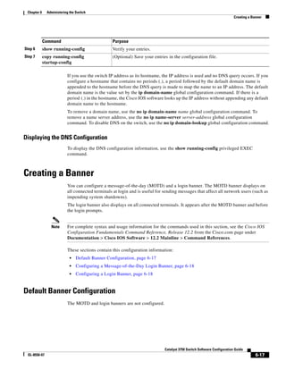
Configuring Summer Time (Daylight Saving Time)
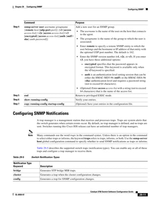
Beginning in privileged EXEC mode, follow these steps to configure summer time (daylight saving time)
in areas where it starts and ends on a particular day of the week each year:
The first part of the clock summer-time global configuration command specifies when summer time
begins, and the second part specifies when it ends. All times are relative to the local time zone. The start
time is relative to standard time. The end time is relative to summer time. If the starting month is after
the ending month, the system assumes that you are in the southern hemisphere.
This example shows how to specify that summer time starts on the first Sunday in April at 02:00 and
ends on the last Sunday in October at 02:00:
Switch(config)# clock summer-time PDT recurring 1 Sunday April 2:00 last Sunday October
2:00
Command Purpose
Step 1 configure terminal Enter global configuration mode.
Step 2 clock summer-time zone recurring
[week day month hh:mm week day month
hh:mm [offset]]
Configure summer time to start and end on the specified days every year.
Summer time is disabled by default. If you specify clock summer-time
zone recurring without parameters, the summer time rules default to the
United States rules.
• For zone, specify the name of the time zone (for example, PDT) to be
displayed when summer time is in effect.
• (Optional) For week, specify the week of the month (1 to 5 or last).
• (Optional) For day, specify the day of the week (Sunday, Monday...).
• (Optional) For month, specify the month (January, February...).
• (Optional) For hh:mm, specify the time (24-hour format) in hours and
minutes.
• (Optional) For offset, specify the number of minutes to add during
summer time. The default is 60.
Step 3 end Return to privileged EXEC mode.
Step 4 show running-config Verify your entries.
Step 5 copy running-config startup-config (Optional) Save your entries in the configuration file.](https://image.slidesharecdn.com/2960scg-150701081942-lva1-app6891/85/Cisco-2960-Switch-Configuration-139-320.jpg)
![6-14
Catalyst 3750 Switch Software Configuration Guide
OL-8550-07
Chapter 6 Administering the Switch
Configuring a System Name and Prompt
Beginning in privileged EXEC mode, follow these steps if summer time in your area does not follow a
recurring pattern (configure the exact date and time of the next summer time events):
The first part of the clock summer-time global configuration command specifies when summer time
begins, and the second part specifies when it ends. All times are relative to the local time zone. The start
time is relative to standard time. The end time is relative to summer time. If the starting month is after
the ending month, the system assumes that you are in the southern hemisphere.
To disable summer time, use the no clock summer-time global configuration command.
This example shows how to set summer time to start on October 12, 2000, at 02:00, and end on April 26,
2001, at 02:00:
Switch(config)# clock summer-time pdt date 12 October 2000 2:00 26 April 2001 2:00
Configuring a System Name and Prompt
You configure the system name on the switch to identify it. By default, the system name and prompt are
Switch.
If you have not configured a system prompt, the first 20 characters of the system name are used as the
system prompt. A greater-than symbol [>] is appended. The prompt is updated whenever the system
name changes.
For complete syntax and usage information for the commands used in this section, from the Cisco.com
page, select Documentation > Cisco IOS Software > 12.2 Mainline > Command References and see
the Cisco IOS Configuration Fundamentals Command Reference and the Cisco IOS IP Command
Reference, Volume 2 of 3: Routing Protocols.
Command Purpose
Step 1 configure terminal Enter global configuration mode.
Step 2 clock summer-time zone date [month
date year hh:mm month date year hh:mm
[offset]]
or
clock summer-time zone date [date
month year hh:mm date month year
hh:mm [offset]]
Configure summer time to start on the first date and end on the second
date.
Summer time is disabled by default.
• For zone, specify the name of the time zone (for example, PDT) to be
displayed when summer time is in effect.
• (Optional) For week, specify the week of the month (1 to 5 or last).
• (Optional) For day, specify the day of the week (Sunday, Monday...).
• (Optional) For month, specify the month (January, February...).
• (Optional) For hh:mm, specify the time (24-hour format) in hours and
minutes.
• (Optional) For offset, specify the number of minutes to add during
summer time. The default is 60.
Step 3 end Return to privileged EXEC mode.
Step 4 show running-config Verify your entries.
Step 5 copy running-config startup-config (Optional) Save your entries in the configuration file.](https://image.slidesharecdn.com/2960scg-150701081942-lva1-app6891/85/Cisco-2960-Switch-Configuration-140-320.jpg)
![6-16
Catalyst 3750 Switch Software Configuration Guide
OL-8550-07
Chapter 6 Administering the Switch
Configuring a System Name and Prompt
These sections contain this configuration information:
• Default DNS Configuration, page 6-16
• Setting Up DNS, page 6-16
• Displaying the DNS Configuration, page 6-17
Default DNS Configuration
Table 6-2 shows the default DNS configuration.
Setting Up DNS
Beginning in privileged EXEC mode, follow these steps to set up your switch to use the DNS:
Table 6-2 Default DNS Configuration
Feature Default Setting
DNS enable state Enabled.
DNS default domain name None configured.
DNS servers No name server addresses are configured.
Command Purpose
Step 1 configure terminal Enter global configuration mode.
Step 2 ip domain-name name Define a default domain name that the software uses to complete unqualified
hostnames (names without a dotted-decimal domain name).
Do not include the initial period that separates an unqualified name from the
domain name.
At boot-up time, no domain name is configured; however, if the switch
configuration comes from a BOOTP or Dynamic Host Configuration Protocol
(DHCP) server, then the default domain name might be set by the BOOTP or
DHCP server (if the servers were configured with this information).
Step 3 ip name-server server-address1
[server-address2 ...
server-address6]
Specify the address of one or more name servers to use for name and address
resolution.
You can specify up to six name servers. Separate each server address with a
space. The first server specified is the primary server. The switch sends DNS
queries to the primary server first. If that query fails, the backup servers are
queried.
Step 4 ip domain-lookup (Optional) Enable DNS-based hostname-to-address translation on your switch.
This feature is enabled by default.
If your network devices require connectivity with devices in networks for which
you do not control name assignment, you can dynamically assign device names
that uniquely identify your devices by using the global Internet naming scheme
(DNS).
Step 5 end Return to privileged EXEC mode.](https://image.slidesharecdn.com/2960scg-150701081942-lva1-app6891/85/Cisco-2960-Switch-Configuration-142-320.jpg)
![6-18
Catalyst 3750 Switch Software Configuration Guide
OL-8550-07
Chapter 6 Administering the Switch
Creating a Banner
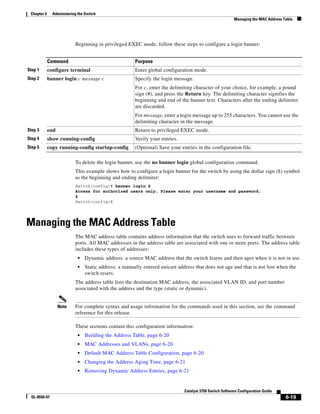
Configuring a Message-of-the-Day Login Banner
You can create a single or multiline message banner that appears on the screen when someone logs in to
the switch.
Beginning in privileged EXEC mode, follow these steps to configure a MOTD login banner:
To delete the MOTD banner, use the no banner motd global configuration command.
This example shows how to configure a MOTD banner for the switch by using the pound sign (#) symbol
as the beginning and ending delimiter:
Switch(config)# banner motd #
This is a secure site. Only authorized users are allowed.
For access, contact technical support.
#
Switch(config)#
This example shows the banner that appears from the previous configuration:
Unix> telnet 172.2.5.4
Trying 172.2.5.4...
Connected to 172.2.5.4.
Escape character is '^]'.
This is a secure site. Only authorized users are allowed.
For access, contact technical support.
User Access Verification
Password:
Configuring a Login Banner
You can configure a login banner to be displayed on all connected terminals. This banner appears after
the MOTD banner and before the login prompt.
Command Purpose
Step 1 configure terminal Enter global configuration mode.
Step 2 banner motd c message c Specify the message of the day.
For c, enter the delimiting character of your choice, for example, a
pound sign (#), and press the Return key. The delimiting character
signifies the beginning and end of the banner text. Characters after the
ending delimiter are discarded.
For message, enter a banner message up to 255 characters. You cannot
use the delimiting character in the message.
Step 3 end Return to privileged EXEC mode.
Step 4 show running-config Verify your entries.
Step 5 copy running-config startup-config (Optional) Save your entries in the configuration file.](https://image.slidesharecdn.com/2960scg-150701081942-lva1-app6891/85/Cisco-2960-Switch-Configuration-144-320.jpg)
![6-21
Catalyst 3750 Switch Software Configuration Guide
OL-8550-07
Chapter 6 Administering the Switch
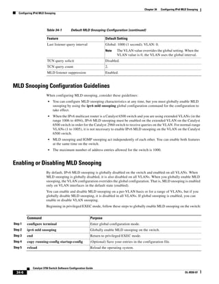
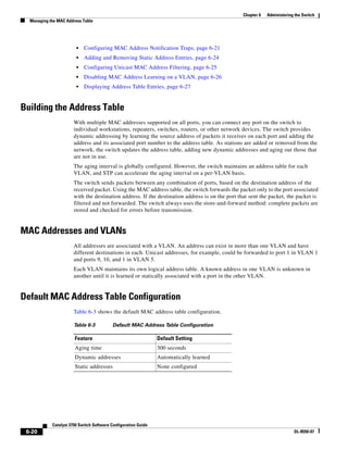
Managing the MAC Address Table
Changing the Address Aging Time
Dynamic addresses are source MAC addresses that the switch learns and then ages when they are not in
use. You can change the aging time setting for all VLANs or for a specified VLAN.
Setting too short an aging time can cause addresses to be prematurely removed from the table. Then
when the switch receives a packet for an unknown destination, it floods the packet to all ports in the same
VLAN as the receiving port. This unnecessary flooding can impact performance. Setting too long an
aging time can cause the address table to be filled with unused addresses, which prevents new addresses
from being learned. Flooding results, which can impact switch performance.
Beginning in privileged EXEC mode, follow these steps to configure the dynamic address table aging
time:
To return to the default value, use the no mac address-table aging-time global configuration command.
Removing Dynamic Address Entries
To remove all dynamic entries, use the clear mac address-table dynamic command in privileged EXEC
mode. You can also remove a specific MAC address (clear mac address-table dynamic address
mac-address), remove all addresses on the specified physical port or port channel (clear mac
address-table dynamic interface interface-id), or remove all addresses on a specified VLAN (clear
mac address-table dynamic vlan vlan-id).
To verify that dynamic entries have been removed, use the show mac address-table dynamic privileged
EXEC command.
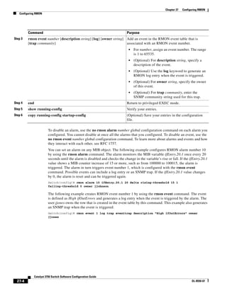
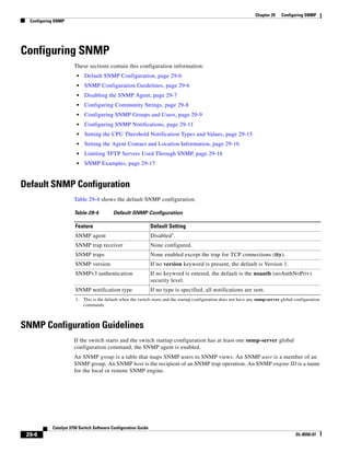
Configuring MAC Address Notification Traps
MAC address notification enables you to track users on a network by storing the MAC address activity
on the switch. Whenever the switch learns or removes a MAC address, an SNMP notification can be
generated and sent to the NMS. If you have many users coming and going from the network, you can set
a trap interval time to bundle the notification traps and reduce network traffic. The MAC notification
history table stores the MAC address activity for each hardware port for which the trap is enabled. MAC
address notifications are generated for dynamic and secure MAC addresses; events are not generated for
self addresses, multicast addresses, or other static addresses.
Command Purpose
Step 1 configure terminal Enter global configuration mode.
Step 2 mac address-table aging-time [0 |
10-1000000] [vlan vlan-id]
Set the length of time that a dynamic entry remains in the MAC
address table after the entry is used or updated.
The range is 10 to 1000000 seconds. The default is 300. You can also
enter 0, which disables aging. Static address entries are never aged
or removed from the table.
For vlan-id, valid IDs are 1 to 4094.
Step 3 end Return to privileged EXEC mode.
Step 4 show mac address-table aging-time Verify your entries.
Step 5 copy running-config startup-config (Optional) Save your entries in the configuration file.](https://image.slidesharecdn.com/2960scg-150701081942-lva1-app6891/85/Cisco-2960-Switch-Configuration-147-320.jpg)
![6-22
Catalyst 3750 Switch Software Configuration Guide
OL-8550-07
Chapter 6 Administering the Switch
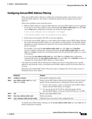
Managing the MAC Address Table
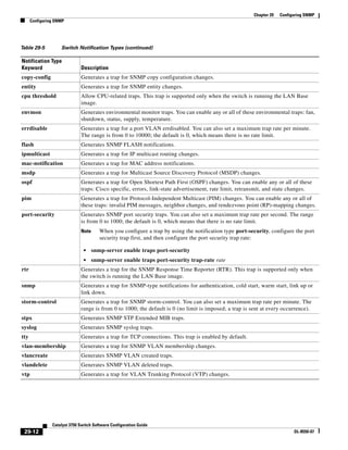
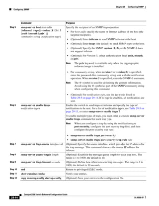
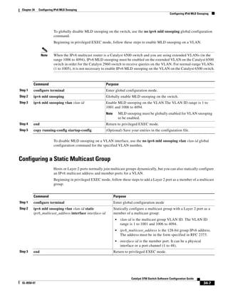
Beginning in privileged EXEC mode, follow these steps to configure the switch to send MAC address
notification traps to an NMS host:
Command Purpose
Step 1 configure terminal Enter global configuration mode.
Step 2 snmp-server host host-addr {traps | informs} {version {1
| 2c | 3}} community-string notification-type
Specify the recipient of the trap message.
• For host-addr, specify the name or address of the
NMS.
• Specify traps (the default) to send SNMP traps
to the host. Specify informs to send SNMP
informs to the host.
• Specify the SNMP version to support. Version 1,
the default, is not available with informs.
• For community-string, specify the string to send
with the notification operation. Though you can
set this string by using the snmp-server host
command, we recommend that you define this
string by using the snmp-server community
command before using the snmp-server host
command.
• For notification-type, use the mac-notification
keyword.
Step 3 snmp-server enable traps mac-notification Enable the switch to send MAC address traps to the
NMS.
Step 4 mac address-table notification Enable the MAC address notification feature.
Step 5 mac address-table notification [interval value] |
[history-size value]
Enter the trap interval time and the history table size.
• (Optional) For interval value, specify the
notification trap interval in seconds between
each set of traps that are generated to the NMS.
The range is 0 to 2147483647 seconds; the
default is 1 second.
• (Optional) For history-size value, specify the
maximum number of entries in the MAC
notification history table. The range is 0 to 500;
the default is 1.
Step 6 interface interface-id Enter interface configuration mode, and specify the
interface on which to enable the SNMP MAC
address notification trap.
Step 7 snmp trap mac-notification {added | removed} Enable the MAC address notification trap.
• Enable the MAC notification trap whenever a
MAC address is added on this interface.
• Enable the MAC notification trap whenever a
MAC address is removed from this interface.
Step 8 end Return to privileged EXEC mode.](https://image.slidesharecdn.com/2960scg-150701081942-lva1-app6891/85/Cisco-2960-Switch-Configuration-148-320.jpg)
![6-23
Catalyst 3750 Switch Software Configuration Guide
OL-8550-07
Chapter 6 Administering the Switch
Managing the MAC Address Table
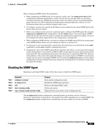
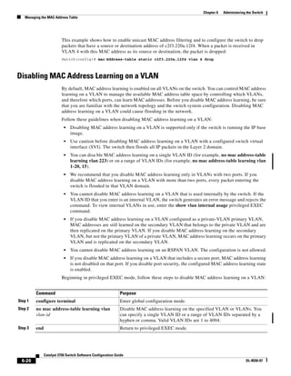
To disable the switch from sending MAC address notification traps, use the no snmp-server enable
traps mac-notification global configuration command. To disable the MAC address notification traps
on a specific interface, use the no snmp trap mac-notification {added | removed} interface
configuration command. To disable the MAC address notification feature, use the no mac address-table
notification global configuration command.
This example shows how to specify 172.20.10.10 as the NMS, enable the switch to send MAC address
notification traps to the NMS, enable the MAC address notification feature, set the interval time to
60 seconds, set the history-size to 100 entries, and enable traps whenever a MAC address is added on
the specified port.
Switch(config)# snmp-server host 172.20.10.10 traps private
Switch(config)# snmp-server enable traps mac-notification
Switch(config)# mac address-table notification
Switch(config)# mac address-table notification interval 60
Switch(config)# mac address-table notification history-size 100
Switch(config)# interface gigabitethernet0/2
Switch(config-if)# snmp trap mac-notification added
You can verify the previous commands by entering the show mac address-table notification interface
and the show mac address-table notification privileged EXEC commands.
Step 4 mac address-table notification Enable the MAC address notification feature.
Step 5 mac address-table notification [interval value] |
[history-size value]
Enter the trap interval time and the history table size.
• (Optional) For interval value, specify the
notification trap interval in seconds between
each set of traps that are generated to the NMS.
The range is 0 to 2147483647 seconds; the
default is 1 second.
• (Optional) For history-size value, specify the
maximum number of entries in the MAC
notification history table. The range is 0 to 500;
the default is 1.
Step 6 interface interface-id Enter interface configuration mode, and specify the
interface on which to enable the SNMP MAC
address notification trap.
Step 7 snmp trap mac-notification {added | removed} Enable the MAC address notification trap.
• Enable the MAC notification trap whenever a
MAC address is added on this interface.
• Enable the MAC notification trap whenever a
MAC address is removed from this interface.
Step 8 end Return to privileged EXEC mode.](https://image.slidesharecdn.com/2960scg-150701081942-lva1-app6891/85/Cisco-2960-Switch-Configuration-149-320.jpg)
![6-24
Catalyst 3750 Switch Software Configuration Guide
OL-8550-07
Chapter 6 Administering the Switch
Managing the MAC Address Table
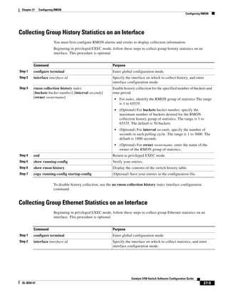
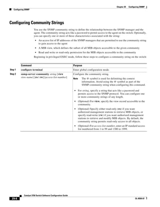
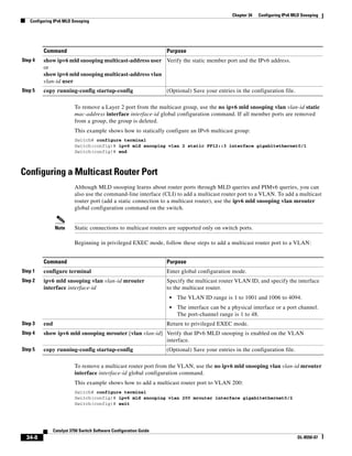
Adding and Removing Static Address Entries
A static address has these characteristics:
• It is manually entered in the address table and must be manually removed.
• It can be a unicast or multicast address.
• It does not age and is retained when the switch restarts.
You can add and remove static addresses and define the forwarding behavior for them. The forwarding
behavior defines how a port that receives a packet forwards it to another port for transmission. Because
all ports are associated with at least one VLAN, the switch acquires the VLAN ID for the address from
the ports that you specify. You can specify a different list of destination ports for each source port.
A packet with a static address that arrives on a VLAN where it has not been statically entered is flooded
to all ports and not learned.
You add a static address to the address table by specifying the destination MAC unicast address and the
VLAN from which it is received. Packets received with this destination address are forwarded to the
interface specified with the interface-id option.
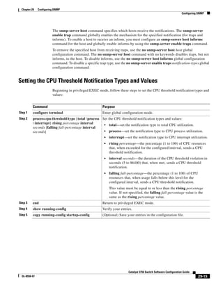
Beginning in privileged EXEC mode, follow these steps to add a static address:
To remove static entries from the address table, use the no mac address-table static mac-addr vlan
vlan-id [interface interface-id] global configuration command.
This example shows how to add the static address c2f3.220a.12f4 to the MAC address table. When a
packet is received in VLAN 4 with this MAC address as its destination address, the packet is forwarded
to the specified port:
Switch(config)# mac address-table static c2f3.220a.12f4 vlan 4 interface
gigabitethernet0/1
Command Purpose
Step 1 configure terminal Enter global configuration mode.
Step 2 mac address-table static mac-addr
vlan vlan-id interface interface-id
Add a static address to the MAC address table.
• For mac-addr, specify the destination MAC unicast address to add to
the address table. Packets with this destination address received in the
specified VLAN are forwarded to the specified interface.
• For vlan-id, specify the VLAN for which the packet with the
specified MAC address is received. Valid VLAN IDs are 1 to 4094.
• For interface-id, specify the interface to which the received packet is
forwarded. Valid interfaces include physical ports or port channels.
For static multicast addresses, you can enter multiple interface IDs.
For static unicast addresses, you can enter only one interface at a
time, but you can enter the command multiple times with the same
MAC address and VLAN ID.
Step 3 end Return to privileged EXEC mode.
Step 4 show mac address-table static Verify your entries.
Step 5 copy running-config startup-config (Optional) Save your entries in the configuration file.](https://image.slidesharecdn.com/2960scg-150701081942-lva1-app6891/85/Cisco-2960-Switch-Configuration-150-320.jpg)
![6-27
Catalyst 3750 Switch Software Configuration Guide
OL-8550-07
Chapter 6 Administering the Switch
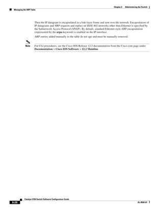
Managing the ARP Table
To reenable MAC address learning on a VLAN, use the default mac address-table learning vlan
vlan-id global configuration command. You can also reenable MAC address learning on a VLAN by
entering the mac address-table learning vlan vlan-id global configuration command. The first
(default) command returns to a default condition and therefore does not appear in the output from the
show running-config command. The second command causes the configuration to appear in the show
running-config privileged EXEC command display.
This example shows how to disable MAC address learning on VLAN 200:
Switch(config)# no mac address-table learning vlan 200
You can display the MAC address learning status of all VLANs or a specified VLAN by entering the
show mac-address-table learning [vlan vlan-id] privileged EXEC command.
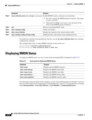
Displaying Address Table Entries
You can display the MAC address table by using one or more of the privileged EXEC commands
described in Table 6-4:
Managing the ARP Table
To communicate with a device (over Ethernet, for example), the software first must learn the 48-bit MAC
address or the local data link address of that device. The process of learning the local data link address
from an IP address is called address resolution.
The Address Resolution Protocol (ARP) associates a host IP address with the corresponding media or
MAC addresses and the VLAN ID. Using an IP address, ARP finds the associated MAC address. When
a MAC address is found, the IP-MAC address association is stored in an ARP cache for rapid retrieval.
Step 4 show mac address-table learning [vlan
vlan-id]
Verify the configuration.
Step 5 copy running-config startup-config (Optional) Save your entries in the configuration file.
Command Purpose
Table 6-4 Commands for Displaying the MAC Address Table
Command Description
show ip igmp snooping groups Displays the Layer 2 multicast entries for all VLANs or the specified VLAN.
show mac address-table address Displays MAC address table information for the specified MAC address.
show mac address-table aging-time Displays the aging time in all VLANs or the specified VLAN.
show mac address-table count Displays the number of addresses present in all VLANs or the specified VLAN.
show mac address-table dynamic Displays only dynamic MAC address table entries.
show mac address-table interface Displays the MAC address table information for the specified interface.
show mac address-table learning Displays MAC address learning status of all VLANs or the specified VLAN.
show mac address-table notification Displays the MAC notification parameters and history table.
show mac address-table static Displays only static MAC address table entries.
show mac address-table vlan Displays the MAC address table information for the specified VLAN.](https://image.slidesharecdn.com/2960scg-150701081942-lva1-app6891/85/Cisco-2960-Switch-Configuration-153-320.jpg)
![7-3
Catalyst 3750 Switch Software Configuration Guide
OL-8550-07
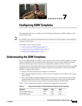
Chapter 7 Configuring SDM Templates
.Displaying the SDM Templates
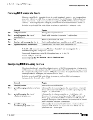
Setting the SDM Template
Beginning in privileged EXEC mode, follow these steps to use the SDM template to maximize feature
usage:
After the system reboots, you can use the show sdm prefer privileged EXEC command to verify the new
template configuration. If you enter the show sdm prefer command before you enter the reload
privileged EXEC command, the show sdm prefer command shows the template currently in use and the
template that will become active after a reload.
.Displaying the SDM Templates
Use the show sdm prefer privileged EXEC command with no parameters to display the active template.
Use the show sdm prefer [default | dual-ipv4-and-ipv6 default | qos] privileged EXEC command to
display the resource numbers supported by the specified template.
Command Purpose
Step 1 configure terminal Enter global configuration mode.
Step 2 sdm prefer {default | dual-ipv4-and-ipv6
default | qos}
Specify the SDM template to be used on the switch:
The keywords have these meanings:
• default—Gives balance to all functions.
• dual-ipv4-and-ipv6 default—Allows the switch to be used in
dual stack environments (supporting both IPv4 and IPv6).
• qos—Maximizes system resources for QoS ACEs.
Use the no sdm prefer command to set the switch to the default
template.
The default template balances the use of system resources.
Step 3 end Return to privileged EXEC mode.
Step 4 reload Reload the operating system.](https://image.slidesharecdn.com/2960scg-150701081942-lva1-app6891/85/Cisco-2960-Switch-Configuration-157-320.jpg)

![8-4
Catalyst 3750 Switch Software Configuration Guide
OL-8550-07
Chapter 8 Configuring Switch-Based Authentication
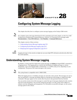
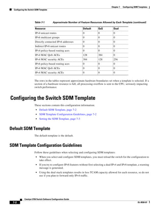
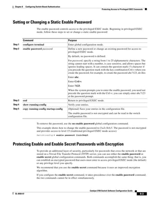
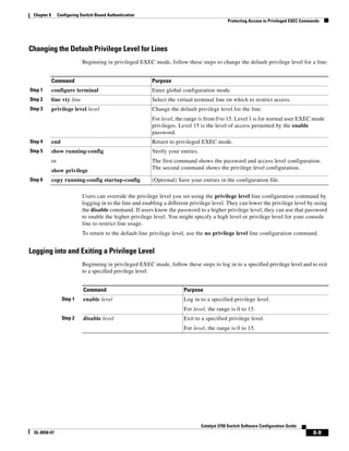
Protecting Access to Privileged EXEC Commands
Beginning in privileged EXEC mode, follow these steps to configure encryption for enable and enable
secret passwords:
If both the enable and enable secret passwords are defined, users must enter the enable secret password.
Use the level keyword to define a password for a specific privilege level. After you specify the level and
set a password, give the password only to users who need to have access at this level. Use the privilege
level global configuration command to specify commands accessible at various levels. For more
information, see the “Configuring Multiple Privilege Levels” section on page 8-7.
If you enable password encryption, it applies to all passwords including username passwords,
authentication key passwords, the privileged command password, and console and virtual terminal line
passwords.
To remove a password and level, use the no enable password [level level] or no enable secret [level
level] global configuration command. To disable password encryption, use the no service
password-encryption global configuration command.
Command Purpose
Step 1 configure terminal Enter global configuration mode.
Step 2 enable password [level level] {password |
encryption-type encrypted-password}
or
enable secret [level level] {password |
encryption-type encrypted-password}
Define a new password or change an existing password for
access to privileged EXEC mode.
or
Define a secret password, which is saved using a
nonreversible encryption method.
• (Optional) For level, the range is from 0 to 15. Level 1
is normal user EXEC mode privileges. The default level
is 15 (privileged EXEC mode privileges).
• For password, specify a string from 1 to 25
alphanumeric characters. The string cannot start with a
number, is case sensitive, and allows spaces but ignores
leading spaces. By default, no password is defined.
• (Optional) For encryption-type, only type 5, a Cisco
proprietary encryption algorithm, is available. If you
specify an encryption type, you must provide an
encrypted password—an encrypted password that you
copy from another switch configuration.
Note If you specify an encryption type and then enter a
clear text password, you can not re-enter privileged
EXEC mode. You cannot recover a lost encrypted
password by any method.
Step 3 service password-encryption (Optional) Encrypt the password when the password is
defined or when the configuration is written.
Encryption prevents the password from being readable in the
configuration file.
Step 4 end Return to privileged EXEC mode.
Step 5 copy running-config startup-config (Optional) Save your entries in the configuration file.](https://image.slidesharecdn.com/2960scg-150701081942-lva1-app6891/85/Cisco-2960-Switch-Configuration-162-320.jpg)
![8-7
Catalyst 3750 Switch Software Configuration Guide
OL-8550-07
Chapter 8 Configuring Switch-Based Authentication
Protecting Access to Privileged EXEC Commands
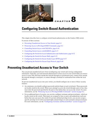
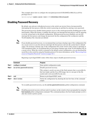
Beginning in privileged EXEC mode, follow these steps to establish a username-based authentication
system that requests a login username and a password:
To disable username authentication for a specific user, use the no username name global configuration
command. To disable password checking and allow connections without a password, use the no login
line configuration command.
Configuring Multiple Privilege Levels
By default, the Cisco IOS software has two modes of password security: user EXEC and privileged
EXEC. You can configure up to 16 hierarchical levels of commands for each mode. By configuring
multiple passwords, you can allow different sets of users to have access to specified commands.
For example, if you want many users to have access to the clear line command, you can assign it
level 2 security and distribute the level 2 password fairly widely. But if you want more restricted access
to the configure command, you can assign it level 3 security and distribute that password to a more
restricted group of users.
These sections contain this configuration information:
• Setting the Privilege Level for a Command, page 8-8
• Changing the Default Privilege Level for Lines, page 8-9
• Logging into and Exiting a Privilege Level, page 8-9
Command Purpose
Step 1 configure terminal Enter global configuration mode.
Step 2 username name [privilege level]
{password encryption-type password}
Enter the username, privilege level, and password for each user.
• For name, specify the user ID as one word. Spaces and quotation
marks are not allowed.
• (Optional) For level, specify the privilege level the user has after
gaining access. The range is 0 to 15. Level 15 gives privileged EXEC
mode access. Level 1 gives user EXEC mode access.
• For encryption-type, enter 0 to specify that an unencrypted password
will follow. Enter 7 to specify that a hidden password will follow.
• For password, specify the password the user must enter to gain access
to the switch. The password must be from 1 to 25 characters, can
contain embedded spaces, and must be the last option specified in the
username command.
Step 3 line console 0
or
line vty 0 15
Enter line configuration mode, and configure the console port (line 0) or
the VTY lines (line 0 to 15).
Step 4 login local Enable local password checking at login time. Authentication is based on
the username specified in Step 2.
Step 5 end Return to privileged EXEC mode.
Step 6 show running-config Verify your entries.
Step 7 copy running-config startup-config (Optional) Save your entries in the configuration file.](https://image.slidesharecdn.com/2960scg-150701081942-lva1-app6891/85/Cisco-2960-Switch-Configuration-165-320.jpg)
![8-13
Catalyst 3750 Switch Software Configuration Guide
OL-8550-07
Chapter 8 Configuring Switch-Based Authentication
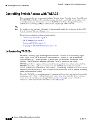
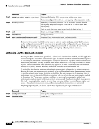
Controlling Switch Access with TACACS+
These sections contain this configuration information:
• Default TACACS+ Configuration, page 8-13
• Identifying the TACACS+ Server Host and Setting the Authentication Key, page 8-13
• Configuring TACACS+ Login Authentication, page 8-14
• Configuring TACACS+ Authorization for Privileged EXEC Access and Network Services,
page 8-16
• Starting TACACS+ Accounting, page 8-17
Default TACACS+ Configuration
TACACS+ and AAA are disabled by default.
To prevent a lapse in security, you cannot configure TACACS+ through a network management
application. When enabled, TACACS+ can authenticate users accessing the switch through the CLI.
Note Although TACACS+ configuration is performed through the CLI, the TACACS+ server authenticates
HTTP connections that have been configured with a privilege level of 15.
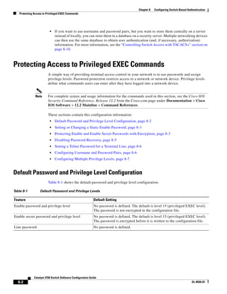
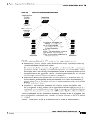
Identifying the TACACS+ Server Host and Setting the Authentication Key
You can configure the switch to use a single server or AAA server groups to group existing server hosts
for authentication. You can group servers to select a subset of the configured server hosts and use them
for a particular service. The server group is used with a global server-host list and contains the list of IP
addresses of the selected server hosts.
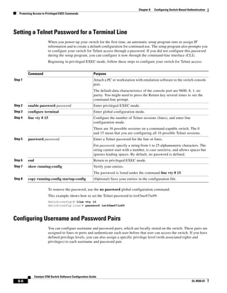
Beginning in privileged EXEC mode, follow these steps to identify the IP host or host maintaining
TACACS+ server and optionally set the encryption key:
Command Purpose
Step 1 configure terminal Enter global configuration mode.
Step 2 tacacs-server host hostname [port
integer] [timeout integer] [key string]
Identify the IP host or hosts maintaining a TACACS+ server. Enter this
command multiple times to create a list of preferred hosts. The software
searches for hosts in the order in which you specify them.
• For hostname, specify the name or IP address of the host.
• (Optional) For port integer, specify a server port number. The default
is port 49. The range is 1 to 65535.
• (Optional) For timeout integer, specify a time in seconds the switch
waits for a response from the daemon before it times out and declares
an error. The default is 5 seconds. The range is 1 to 1000 seconds.
• (Optional) For key string, specify the encryption key for encrypting
and decrypting all traffic between the switch and the TACACS+
daemon. You must configure the same key on the TACACS+ daemon
for encryption to be successful.
Step 3 aaa new-model Enable AAA.](https://image.slidesharecdn.com/2960scg-150701081942-lva1-app6891/85/Cisco-2960-Switch-Configuration-171-320.jpg)
![8-15
Catalyst 3750 Switch Software Configuration Guide
OL-8550-07
Chapter 8 Configuring Switch-Based Authentication
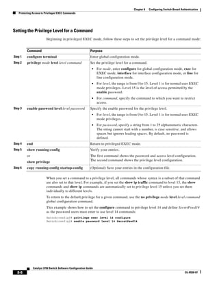
Controlling Switch Access with TACACS+
Step 3 aaa authentication login {default |
list-name} method1 [method2...]
Create a login authentication method list.
• To create a default list that is used when a named list is not specified
in the login authentication command, use the default keyword
followed by the methods that are to be used in default situations. The
default method list is automatically applied to all ports.
• For list-name, specify a character string to name the list you are
creating.
• For method1..., specify the actual method the authentication
algorithm tries. The additional methods of authentication are used
only if the previous method returns an error, not if it fails.
Select one of these methods:
• enable—Use the enable password for authentication. Before you can
use this authentication method, you must define an enable password
by using the enable password global configuration command.
• group tacacs+—Uses TACACS+ authentication. Before you can use
this authentication method, you must configure the TACACS+
server. For more information, see the “Identifying the TACACS+
Server Host and Setting the Authentication Key” section on
page 8-13.
• line—Use the line password for authentication. Before you can use
this authentication method, you must define a line password. Use the
password password line configuration command.
• local—Use the local username database for authentication. You must
enter username information in the database. Use the username
password global configuration command.
• local-case—Use a case-sensitive local username database for
authentication. You must enter username information in the database
by using the username name password global configuration
command.
• none—Do not use any authentication for login.
Step 4 line [console | tty | vty] line-number
[ending-line-number]
Enter line configuration mode, and configure the lines to which you want
to apply the authentication list.
Step 5 login authentication {default |
list-name}
Apply the authentication list to a line or set of lines.
• If you specify default, use the default list created with the aaa
authentication login command.
• For list-name, specify the list created with the aaa authentication
login command.
Step 6 end Return to privileged EXEC mode.
Step 7 show running-config Verify your entries.
Step 8 copy running-config startup-config (Optional) Save your entries in the configuration file.
Command Purpose](https://image.slidesharecdn.com/2960scg-150701081942-lva1-app6891/85/Cisco-2960-Switch-Configuration-173-320.jpg)
![8-16
Catalyst 3750 Switch Software Configuration Guide
OL-8550-07
Chapter 8 Configuring Switch-Based Authentication
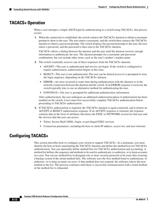
Controlling Switch Access with TACACS+
To disable AAA, use the no aaa new-model global configuration command. To disable AAA
authentication, use the no aaa authentication login {default | list-name} method1 [method2...] global
configuration command. To either disable TACACS+ authentication for logins or to return to the default
value, use the no login authentication {default | list-name} line configuration command.
Note To secure the switch for HTTP access by using AAA methods, you must configure the switch with the
ip http authentication aaa global configuration command. Configuring AAA authentication does not
secure the switch for HTTP access by using AAA methods.
For more information about the ip http authentication command, see the Cisco IOS Security Command
Reference, Release 12.2 from the Cisco.com page under Documentation > Cisco IOS Software > 12.2
Mainline > Command References.
Configuring TACACS+ Authorization for Privileged EXEC Access and Network Services
AAA authorization limits the services available to a user. When AAA authorization is enabled, the
switch uses information retrieved from the user’s profile, which is located either in the local user
database or on the security server, to configure the user’s session. The user is granted access to a
requested service only if the information in the user profile allows it.
You can use the aaa authorization global configuration command with the tacacs+ keyword to set
parameters that restrict a user’s network access to privileged EXEC mode.
The aaa authorization exec tacacs+ local command sets these authorization parameters:
• Use TACACS+ for privileged EXEC access authorization if authentication was performed by using
TACACS+.
• Use the local database if authentication was not performed by using TACACS+.
Note Authorization is bypassed for authenticated users who log in through the CLI even if authorization has
been configured.
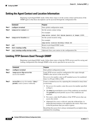
Beginning in privileged EXEC mode, follow these steps to specify TACACS+ authorization for
privileged EXEC access and network services:
Command Purpose
Step 1 configure terminal Enter global configuration mode.
Step 2 aaa authorization network tacacs+ Configure the switch for user TACACS+ authorization for all
network-related service requests.
Step 3 aaa authorization exec tacacs+ Configure the switch for user TACACS+ authorization if the user has
privileged EXEC access.
The exec keyword might return user profile information (such as
autocommand information).
Step 4 end Return to privileged EXEC mode.
Step 5 show running-config Verify your entries.
Step 6 copy running-config startup-config (Optional) Save your entries in the configuration file.](https://image.slidesharecdn.com/2960scg-150701081942-lva1-app6891/85/Cisco-2960-Switch-Configuration-174-320.jpg)
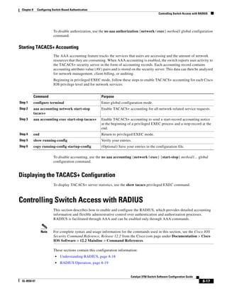
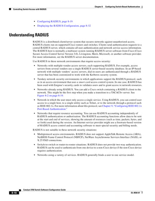
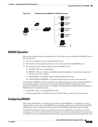
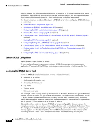
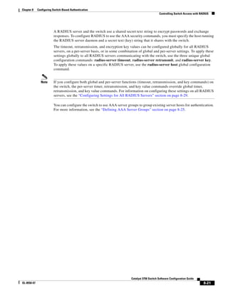
![8-22
Catalyst 3750 Switch Software Configuration Guide
OL-8550-07
Chapter 8 Configuring Switch-Based Authentication
Controlling Switch Access with RADIUS
Beginning in privileged EXEC mode, follow these steps to configure per-server RADIUS server
communication. This procedure is required.
To remove the specified RADIUS server, use the no radius-server host hostname | ip-address global
configuration command.
This example shows how to configure one RADIUS server to be used for authentication and another to
be used for accounting:
Switch(config)# radius-server host 172.29.36.49 auth-port 1612 key rad1
Switch(config)# radius-server host 172.20.36.50 acct-port 1618 key rad2
Command Purpose
Step 1 configure terminal Enter global configuration mode.
Step 2 radius-server host {hostname |
ip-address} [auth-port port-number]
[acct-port port-number] [timeout
seconds] [retransmit retries] [key
string]
Specify the IP address or hostname of the remote RADIUS server host.
• (Optional) For auth-port port-number, specify the UDP destination
port for authentication requests.
• (Optional) For acct-port port-number, specify the UDP destination
port for accounting requests.
• (Optional) For timeout seconds, specify the time interval that the
switch waits for the RADIUS server to reply before resending. The
range is 1 to 1000. This setting overrides the radius-server timeout
global configuration command setting. If no timeout is set with the
radius-server host command, the setting of the radius-server
timeout command is used.
• (Optional) For retransmit retries, specify the number of times a
RADIUS request is resent to a server if that server is not responding
or responding slowly. The range is 1 to 1000. If no retransmit value
is set with the radius-server host command, the setting of the
radius-server retransmit global configuration command is used.
• (Optional) For key string, specify the authentication and encryption
key used between the switch and the RADIUS daemon running on the
RADIUS server.
Note The key is a text string that must match the encryption key used
on the RADIUS server. Always configure the key as the last item
in the radius-server host command. Leading spaces are ignored,
but spaces within and at the end of the key are used. If you use
spaces in your key, do not enclose the key in quotation marks
unless the quotation marks are part of the key.
To configure the switch to recognize more than one host entry associated
with a single IP address, enter this command as many times as necessary,
making sure that each UDP port number is different. The switch software
searches for hosts in the order in which you specify them. Set the timeout,
retransmit, and encryption key values to use with the specific RADIUS
host.
Step 3 end Return to privileged EXEC mode.
Step 4 show running-config Verify your entries.
Step 5 copy running-config startup-config (Optional) Save your entries in the configuration file.](https://image.slidesharecdn.com/2960scg-150701081942-lva1-app6891/85/Cisco-2960-Switch-Configuration-180-320.jpg)
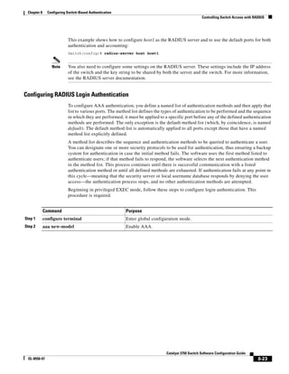
![8-24
Catalyst 3750 Switch Software Configuration Guide
OL-8550-07
Chapter 8 Configuring Switch-Based Authentication
Controlling Switch Access with RADIUS
Step 3 aaa authentication login {default |
list-name} method1 [method2...]
Create a login authentication method list.
• To create a default list that is used when a named list is not specified
in the login authentication command, use the default keyword
followed by the methods that are to be used in default situations. The
default method list is automatically applied to all ports.
• For list-name, specify a character string to name the list you are
creating.
• For method1..., specify the actual method the authentication
algorithm tries. The additional methods of authentication are used
only if the previous method returns an error, not if it fails.
Select one of these methods:
– enable—Use the enable password for authentication. Before you
can use this authentication method, you must define an enable
password by using the enable password global configuration
command.
– group radius—Use RADIUS authentication. Before you can use
this authentication method, you must configure the RADIUS
server. For more information, see the “Identifying the RADIUS
Server Host” section on page 8-20.
– line—Use the line password for authentication. Before you can
use this authentication method, you must define a line password.
Use the password password line configuration command.
– local—Use the local username database for authentication. You
must enter username information in the database. Use the
username name password global configuration command.
– local-case—Use a case-sensitive local username database for
authentication. You must enter username information in the
database by using the username password global configuration
command.
– none—Do not use any authentication for login.
Step 4 line [console | tty | vty] line-number
[ending-line-number]
Enter line configuration mode, and configure the lines to which you want
to apply the authentication list.
Step 5 login authentication {default |
list-name}
Apply the authentication list to a line or set of lines.
• If you specify default, use the default list created with the aaa
authentication login command.
• For list-name, specify the list created with the aaa authentication
login command.
Step 6 end Return to privileged EXEC mode.
Step 7 show running-config Verify your entries.
Step 8 copy running-config startup-config (Optional) Save your entries in the configuration file.
Command Purpose](https://image.slidesharecdn.com/2960scg-150701081942-lva1-app6891/85/Cisco-2960-Switch-Configuration-182-320.jpg)
![8-25
Catalyst 3750 Switch Software Configuration Guide
OL-8550-07
Chapter 8 Configuring Switch-Based Authentication
Controlling Switch Access with RADIUS
To disable AAA, use the no aaa new-model global configuration command. To disable AAA
authentication, use the no aaa authentication login {default | list-name} method1 [method2...] global
configuration command. To either disable RADIUS authentication for logins or to return to the default
value, use the no login authentication {default | list-name} line configuration command.
Note To secure the switch for HTTP access by using AAA methods, you must configure the switch with the
ip http authentication aaa global configuration command. Configuring AAA authentication does not
secure the switch for HTTP access by using AAA methods.
For more information about the ip http authentication command, see the Cisco IOS Security Command
Reference, Release 12.2 from the Cisco.com page under Documentation > Cisco IOS Software > 12.2
Mainline > Command References.
Defining AAA Server Groups
You can configure the switch to use AAA server groups to group existing server hosts for authentication.
You select a subset of the configured server hosts and use them for a particular service. The server group
is used with a global server-host list, which lists the IP addresses of the selected server hosts.
Server groups also can include multiple host entries for the same server if each entry has a unique
identifier (the combination of the IP address and UDP port number), allowing different ports to be
individually defined as RADIUS hosts providing a specific AAA service. If you configure two different
host entries on the same RADIUS server for the same service, (for example, accounting), the second
configured host entry acts as a fail-over backup to the first one.
You use the server group server configuration command to associate a particular server with a defined
group server. You can either identify the server by its IP address or identify multiple host instances or
entries by using the optional auth-port and acct-port keywords.](https://image.slidesharecdn.com/2960scg-150701081942-lva1-app6891/85/Cisco-2960-Switch-Configuration-183-320.jpg)
![8-26
Catalyst 3750 Switch Software Configuration Guide
OL-8550-07
Chapter 8 Configuring Switch-Based Authentication
Controlling Switch Access with RADIUS
Beginning in privileged EXEC mode, follow these steps to define the AAA server group and associate
a particular RADIUS server with it:
Command Purpose
Step 1 configure terminal Enter global configuration mode.
Step 2 radius-server host {hostname |
ip-address} [auth-port port-number]
[acct-port port-number] [timeout
seconds] [retransmit retries] [key
string]
Specify the IP address or hostname of the remote RADIUS server host.
• (Optional) For auth-port port-number, specify the UDP destination
port for authentication requests.
• (Optional) For acct-port port-number, specify the UDP destination
port for accounting requests.
• (Optional) For timeout seconds, specify the time interval that the
switch waits for the RADIUS server to reply before resending. The
range is 1 to 1000. This setting overrides the radius-server timeout
global configuration command setting. If no timeout is set with the
radius-server host command, the setting of the radius-server
timeout command is used.
• (Optional) For retransmit retries, specify the number of times a
RADIUS request is resent to a server if that server is not responding
or responding slowly. The range is 1 to 1000. If no retransmit value
is set with the radius-server host command, the setting of the
radius-server retransmit global configuration command is used.
• (Optional) For key string, specify the authentication and encryption
key used between the switch and the RADIUS daemon running on the
RADIUS server.
Note The key is a text string that must match the encryption key used
on the RADIUS server. Always configure the key as the last item
in the radius-server host command. Leading spaces are ignored,
but spaces within and at the end of the key are used. If you use
spaces in your key, do not enclose the key in quotation marks
unless the quotation marks are part of the key.
To configure the switch to recognize more than one host entry associated
with a single IP address, enter this command as many times as necessary,
making sure that each UDP port number is different. The switch software
searches for hosts in the order in which you specify them. Set the timeout,
retransmit, and encryption key values to use with the specific RADIUS
host.
Step 3 aaa new-model Enable AAA.
Step 4 aaa group server radius group-name Define the AAA server-group with a group name.
This command puts the switch in a server group configuration mode.
Step 5 server ip-address Associate a particular RADIUS server with the defined server group.
Repeat this step for each RADIUS server in the AAA server group.
Each server in the group must be previously defined in Step 2.
Step 6 end Return to privileged EXEC mode.
Step 7 show running-config Verify your entries.](https://image.slidesharecdn.com/2960scg-150701081942-lva1-app6891/85/Cisco-2960-Switch-Configuration-184-320.jpg)
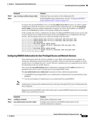
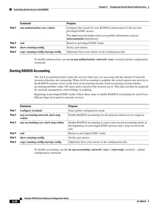
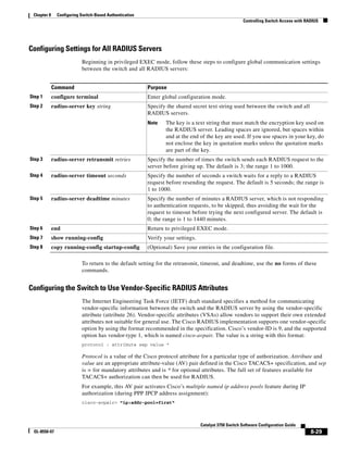
![8-30
Catalyst 3750 Switch Software Configuration Guide
OL-8550-07
Chapter 8 Configuring Switch-Based Authentication
Controlling Switch Access with RADIUS
This example shows how to provide a user logging in from a switch with immediate access to privileged
EXEC commands:
cisco-avpair= ”shell:priv-lvl=15“
This example shows how to specify an authorized VLAN in the RADIUS server database:
cisco-avpair= ”tunnel-type(#64)=VLAN(13)”
cisco-avpair= ”tunnel-medium-type(#65)=802 media(6)”
cisco-avpair= ”tunnel-private-group-ID(#81)=vlanid”
This example shows how to apply an input ACL in ASCII format to an interface for the duration of this
connection:
cisco-avpair= “ip:inacl#1=deny ip 10.10.10.10 0.0.255.255 20.20.20.20 255.255.0.0”
cisco-avpair= “ip:inacl#2=deny ip 10.10.10.10 0.0.255.255 any”
cisco-avpair= “mac:inacl#3=deny any any decnet-iv”
This example shows how to apply an output ACL in ASCII format to an interface for the duration of this
connection:
cisco-avpair= “ip:outacl#2=deny ip 10.10.10.10 0.0.255.255 any”
Other vendors have their own unique vendor-IDs, options, and associated VSAs. For more information
about vendor-IDs and VSAs, see RFC 2138, “Remote Authentication Dial-In User Service (RADIUS).”
Beginning in privileged EXEC mode, follow these steps to configure the switch to recognize and use
VSAs:
Note For a complete list of RADIUS attributes or more information about vendor-specific attribute 26, see the
“RADIUS Attributes” appendix in the Cisco IOS Security Configuration Guide, Release 12.2 from the
Cisco.com page under Documentation > Cisco IOS Software > 12.2 Mainline > Command
References.
Command Purpose
Step 1 configure terminal Enter global configuration mode.
Step 2 radius-server vsa send [accounting |
authentication]
Enable the switch to recognize and use VSAs as defined by RADIUS IETF
attribute 26.
• (Optional) Use the accounting keyword to limit the set of recognized
vendor-specific attributes to only accounting attributes.
• (Optional) Use the authentication keyword to limit the set of
recognized vendor-specific attributes to only authentication attributes.
If you enter this command without keywords, both accounting and
authentication vendor-specific attributes are used.
Step 3 end Return to privileged EXEC mode.
Step 4 show running-config Verify your settings.
Step 5 copy running-config startup-config (Optional) Save your entries in the configuration file.](https://image.slidesharecdn.com/2960scg-150701081942-lva1-app6891/85/Cisco-2960-Switch-Configuration-188-320.jpg)
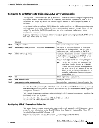
![8-32
Catalyst 3750 Switch Software Configuration Guide
OL-8550-07
Chapter 8 Configuring Switch-Based Authentication
Configuring the Switch for Local Authentication and Authorization
Displaying the RADIUS Configuration
To display the RADIUS configuration, use the show running-config privileged EXEC command.
Configuring the Switch for Local Authentication and
Authorization
You can configure AAA to operate without a server by setting the switch to implement AAA in local
mode. The switch then handles authentication and authorization. No accounting is available in this
configuration.
Beginning in privileged EXEC mode, follow these steps to configure the switch for local AAA:
To disable AAA, use the no aaa new-model global configuration command. To disable authorization,
use the no aaa authorization {network | exec} method1 global configuration command.
Command Purpose
Step 1 configure terminal Enter global configuration mode.
Step 2 aaa new-model Enable AAA.
Step 3 aaa authentication login default local Set the login authentication to use the local username database. The
default keyword applies the local user database authentication to all
ports.
Step 4 aaa authorization exec local Configure user AAA authorization, check the local database, and allow
the user to run an EXEC shell.
Step 5 aaa authorization network local Configure user AAA authorization for all network-related service
requests.
Step 6 username name [privilege level]
{password encryption-type password}
Enter the local database, and establish a username-based authentication
system.
Repeat this command for each user.
• For name, specify the user ID as one word. Spaces and quotation
marks are not allowed.
• (Optional) For level, specify the privilege level the user has after
gaining access. The range is 0 to 15. Level 15 gives privileged EXEC
mode access. Level 0 gives user EXEC mode access.
• For encryption-type, enter 0 to specify that an unencrypted password
follows. Enter 7 to specify that a hidden password follows.
• For password, specify the password the user must enter to gain access
to the switch. The password must be from 1 to 25 characters, can
contain embedded spaces, and must be the last option specified in the
username command.
Step 7 end Return to privileged EXEC mode.
Step 8 show running-config Verify your entries.
Step 9 copy running-config startup-config (Optional) Save your entries in the configuration file.](https://image.slidesharecdn.com/2960scg-150701081942-lva1-app6891/85/Cisco-2960-Switch-Configuration-190-320.jpg)
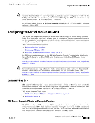
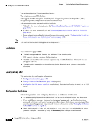
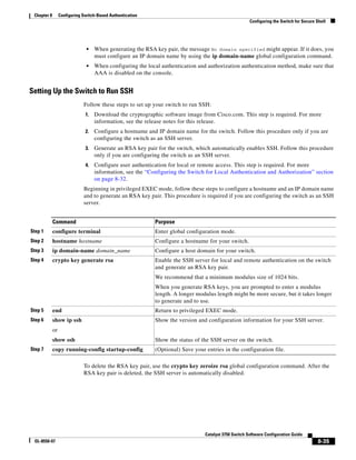
![8-36
Catalyst 3750 Switch Software Configuration Guide
OL-8550-07
Chapter 8 Configuring Switch-Based Authentication
Configuring the Switch for Secure Shell
Configuring the SSH Server
Beginning in privileged EXEC mode, follow these steps to configure the SSH server:
To return to the default SSH control parameters, use the no ip ssh {timeout | authentication-retries}
global configuration command.
Command Purpose
Step 1 configure terminal Enter global configuration mode.
Step 2 ip ssh version [1 | 2] (Optional) Configure the switch to run SSH Version 1 or SSH Version 2.
• 1—Configure the switch to run SSH Version 1.
• 2—Configure the switch to run SSH Version 2.
If you do not enter this command or do not specify a keyword, the SSH
server selects the latest SSH version supported by the SSH client. For
example, if the SSH client supports SSHv1 and SSHv2, the SSH server
selects SSHv2.
Step 3 ip ssh {timeout seconds |
authentication-retries number}
Configure the SSH control parameters:
• Specify the time-out value in seconds; the default is 120 seconds. The
range is 0 to 120 seconds. This parameter applies to the SSH
negotiation phase. After the connection is established, the switch uses
the default time-out values of the CLI-based sessions.
By default, up to five simultaneous, encrypted SSH connections for
multiple CLI-based sessions over the network are available (session
0 to session 4). After the execution shell starts, the CLI-based session
time-out value returns to the default of 10 minutes.
• Specify the number of times that a client can re-authenticate to the
server. The default is 3; the range is 0 to 5.
Repeat this step when configuring both parameters.
Step 4 line vty line_number
[ending_line_number]
transport input ssh
(Optional) Configure the virtual terminal line settings.
• Enter line configuration mode to configure the virtual terminal line
settings. For line_number and ending_line_number, specify a pair of
lines. The range is 0 to 15.
• Specify that the switch prevent non-SSH Telnet connections. This
limits the router to only SSH connections.
Step 5 end Return to privileged EXEC mode.
Step 6 show ip ssh
or
show ssh
Show the version and configuration information for your SSH server.
Show the status of the SSH server connections on the switch.
Step 7 copy running-config startup-config (Optional) Save your entries in the configuration file.](https://image.slidesharecdn.com/2960scg-150701081942-lva1-app6891/85/Cisco-2960-Switch-Configuration-194-320.jpg)
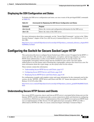
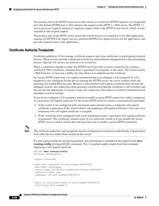
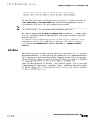
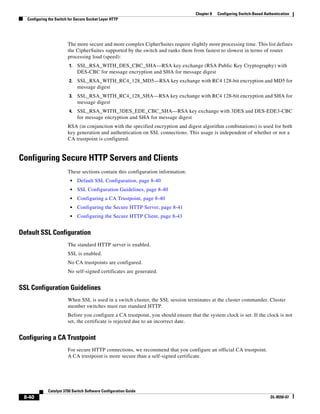
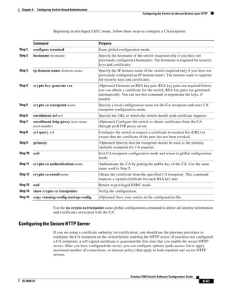
![8-42
Catalyst 3750 Switch Software Configuration Guide
OL-8550-07
Chapter 8 Configuring Switch-Based Authentication
Configuring the Switch for Secure Socket Layer HTTP
Beginning in privileged EXEC mode, follow these steps to configure a secure HTTP server:
Command Purpose
Step 1 show ip http server status (Optional) Display the status of the HTTP server to determine if the
secure HTTP server feature is supported in the software. You should see
one of these lines in the output:
HTTP secure server capability: Present
or
HTTP secure server capability: Not present
Step 2 configure terminal Enter global configuration mode.
Step 3 ip http secure-server Enable the HTTPS server if it has been disabled. The HTTPS server is
enabled by default.
Step 4 ip http secure-port port-number (Optional) Specify the port number to be used for the HTTPS server. The
default port number is 443. Valid options are 443 or any number in the
range 1025 to 65535.
Step 5 ip http secure-ciphersuite
{[3des-ede-cbc-sha] [rc4-128-md5]
[rc4-128-sha] [des-cbc-sha]}
(Optional) Specify the CipherSuites (encryption algorithms) to be used
for encryption over the HTTPS connection. If you do not have a reason to
specify a particularly CipherSuite, you should allow the server and client
to negotiate a CipherSuite that they both support. This is the default.
Step 6 ip http secure-client-auth (Optional) Configure the HTTP server to request an X.509v3 certificate
from the client for authentication during the connection process. The
default is for the client to request a certificate from the server, but the
server does not attempt to authenticate the client.
Step 7 ip http secure-trustpoint name Specify the CA trustpoint to use to get an X.509v3 security certificate and
to authenticate the client certificate connection.
Note Use of this command assumes you have already configured a CA
trustpoint according to the previous procedure.
Step 8 ip http path path-name (Optional) Set a base HTTP path for HTML files. The path specifies the
location of the HTTP server files on the local system (usually located in
system flash memory).
Step 9 ip http access-class access-list-number (Optional) Specify an access list to use to allow access to the HTTP
server.
Step 10 ip http max-connections value (Optional) Set the maximum number of concurrent connections that are
allowed to the HTTP server. The range is 1 to 16; the default value is 5.
Step 11 ip http timeout-policy idle seconds life
seconds requests value
(Optional) Specify how long a connection to the HTTP server can remain
open under the defined circumstances:
• idle—the maximum time period when no data is received or response
data cannot be sent. The range is 1 to 600 seconds. The default is
180 seconds (3 minutes).
• life—the maximum time period from the time that the connection is
established. The range is 1 to 86400 seconds (24 hours). The default
is 180 seconds.
• requests—the maximum number of requests processed on a
persistent connection. The maximum value is 86400. The default is 1.
Step 12 end Return to privileged EXEC mode.](https://image.slidesharecdn.com/2960scg-150701081942-lva1-app6891/85/Cisco-2960-Switch-Configuration-200-320.jpg)
![8-43
Catalyst 3750 Switch Software Configuration Guide
OL-8550-07
Chapter 8 Configuring Switch-Based Authentication
Configuring the Switch for Secure Socket Layer HTTP
Use the no ip http server global configuration command to disable the standard HTTP server. Use the
no ip http secure-server global configuration command to disable the secure HTTP server. Use the no
ip http secure-port and the no ip http secure-ciphersuite global configuration commands to return to
the default settings. Use the no ip http secure-client-auth global configuration command to remove the
requirement for client authentication.
To verify the secure HTTP connection by using a Web browser, enter https://URL, where the URL is the
IP address or hostname of the server switch. If you configure a port other than the default port, you must
also specify the port number after the URL. For example:
https://209.165.129:1026
or
https://host.domain.com:1026
Configuring the Secure HTTP Client
The standard HTTP client and secure HTTP client are always enabled. A certificate authority is required
for secure HTTP client certification. This procedure assumes that you have previously configured a CA
trustpoint on the switch. If a CA trustpoint is not configured and the remote HTTPS server requires client
authentication, connections to the secure HTTP client fail.
Beginning in privileged EXEC mode, follow these steps to configure a secure HTTP client:
Use the no ip http client secure-trustpoint name to remove a client trustpoint configuration. Use the
no ip http client secure-ciphersuite to remove a previously configured CipherSuite specification for
the client.
Step 13 show ip http server secure status Display the status of the HTTP secure server to verify the configuration.
Step 14 copy running-config startup-config (Optional) Save your entries in the configuration file.
Command Purpose
Command Purpose
Step 1 configure terminal Enter global configuration mode.
Step 2 ip http client secure-trustpoint name (Optional) Specify the CA trustpoint to be used if the remote HTTP server
requests client authentication. Using this command assumes that you have
already configured a CA trustpoint by using the previous procedure. The
command is optional if client authentication is not needed or if a primary
trustpoint has been configured.
Step 3 ip http client secure-ciphersuite
{[3des-ede-cbc-sha] [rc4-128-md5]
[rc4-128-sha] [des-cbc-sha]}
(Optional) Specify the CipherSuites (encryption algorithms) to be used
for encryption over the HTTPS connection. If you do not have a reason to
specify a particular CipherSuite, you should allow the server and client to
negotiate a CipherSuite that they both support. This is the default.
Step 4 end Return to privileged EXEC mode.
Step 5 show ip http client secure status Display the status of the HTTP secure server to verify the configuration.
Step 6 copy running-config startup-config (Optional) Save your entries in the configuration file.](https://image.slidesharecdn.com/2960scg-150701081942-lva1-app6891/85/Cisco-2960-Switch-Configuration-201-320.jpg)
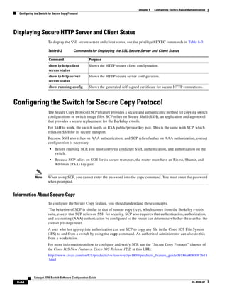
![9-5
Catalyst 3750 Switch Software Configuration Guide
OL-8550-07
Chapter 9 Configuring IEEE 802.1x Port-Based Authentication
Understanding IEEE 802.1x Port-Based Authentication
Figure 9-2 shows the authentication process.
Figure 9-2 Authentication Flowchart
The switch re-authenticates a client when one of these situations occurs:
• Periodic re-authentication is enabled, and the re-authentication timer expires.
You can configure the re-authentication timer to use a switch-specific value or to be based on values
from the RADIUS server.
After 802.1x authentication using a RADIUS server is configured, the switch uses timers based on
the Session-Timeout RADIUS attribute (Attribute[27]) and the Termination-Action RADIUS
attribute (Attribute [29]).
The Session-Timeout RADIUS attribute (Attribute[27]) specifies the time after which
re-authentication occurs.
141679
Yes
No
Client
identity is
invalid
All authentication
servers are down.
All authentication
servers are down.
Client
identity is
valid
The switch gets an
EAPOL message,
and the EAPOL
message
exchange begins.
Yes No
1
1
1
1 = This occurs if the switch does not detect EAPOL packets from the client.
Client MAC
address
identity
is invalid.
Client MAC
address
identity
is valid.
Is the client IEEE
802.1x capable?
Start IEEE 802.1x port-based
authentication.
Use inaccessible
authentication bypass
(critical authentication)
to assign the critical
port to a VLAN.
IEEE 802.1x authentication
process times out.
Is MAC authentication
bypass enabled?
Use MAC authentication
bypass.
Assign the port to
a guest VLAN.
Start
Done
Assign the port to
a VLAN.
Done
Done
Assign the port to
a VLAN.
Done
Assign the port to
a restricted VLAN.
Done](https://image.slidesharecdn.com/2960scg-150701081942-lva1-app6891/85/Cisco-2960-Switch-Configuration-207-320.jpg)
![9-6
Catalyst 3750 Switch Software Configuration Guide
OL-8550-07
Chapter 9 Configuring IEEE 802.1x Port-Based Authentication
Understanding IEEE 802.1x Port-Based Authentication
The Termination-Action RADIUS attribute (Attribute [29]) specifies the action to take during
re-authentication. The actions are Initialize and ReAuthenticate. When the Initialize action is set (the
attribute value is DEFAULT), the 802.1x session ends, and connectivity is lost during
re-authentication. When the ReAuthenticate action is set (the attribute value is RADIUS-Request),
the session is not affected during re-authentication.
• You manually re-authenticate the client by entering the dot1x re-authenticate interface
interface-id privileged EXEC command.
If Multidomain authentication (MDA) is enabled on a port, this flow can be used with some exceptions
that are applicable to voice authorization. For more information on MDA, see “Multidomain
Authentication” section on page 9-12.
Authentication Initiation and Message Exchange
During 802.1x authentication, the switch or the client can initiate authentication. If you enable
authentication on a port by using the authentication port-control auto or dot1x port-control auto
interface configuration command, the switch initiates authentication when the link state changes from
down to up or periodically as long as the port remains up and unauthenticated. The switch sends an
EAP-request/identity frame to the client to request its identity. Upon receipt of the frame, the client
responds with an EAP-response/identity frame.
However, if during boot up, the client does not receive an EAP-request/identity frame from the switch,
the client can initiate authentication by sending an EAPOL-start frame, which prompts the switch to
request the client’s identity.
Note If 802.1x authentication is not enabled or supported on the network access device, any EAPOL frames
from the client are dropped. If the client does not receive an EAP-request/identity frame after three
attempts to start authentication, the client sends frames as if the port is in the authorized state. A port in
the authorized state effectively means that the client has been successfully authenticated. For more
information, see the “Ports in Authorized and Unauthorized States” section on page 9-10.
When the client supplies its identity, the switch begins its role as the intermediary, passing EAP frames
between the client and the authentication server until authentication succeeds or fails. If the
authentication succeeds, the switch port becomes authorized. If the authentication fails, authentication
can be retried, the port might be assigned to a VLAN that provides limited services, or network access
is not granted. For more information, see the “Ports in Authorized and Unauthorized States” section on
page 9-10.
The specific exchange of EAP frames depends on the authentication method being used. Figure 9-3
shows a message exchange initiated by the client when the client uses the One-Time-Password (OTP)
authentication method with a RADIUS server.](https://image.slidesharecdn.com/2960scg-150701081942-lva1-app6891/85/Cisco-2960-Switch-Configuration-208-320.jpg)
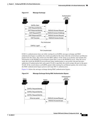
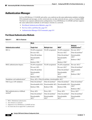
![9-9
Catalyst 3750 Switch Software Configuration Guide
OL-8550-07
Chapter 9 Configuring IEEE 802.1x Port-Based Authentication
Understanding IEEE 802.1x Port-Based Authentication
Per-User ACLs and Filter-Ids
In releases earlier than Cisco IOS Release 12.2(50)SE, an ACL configured on the switch is not
compatible with an ACL configured on another device running Cisco IOS software, such as a
Catalyst 6000 switch.
In Cisco IOS Release 12.2(50)SE or later, the ACLs configured on the switch are compatible with other
devices running Cisco IOS release.
You can only set any as the source in the ACL.
Authentication Manager CLI Commands
The authentication-manager interface-configuration commands control all the authentication methods,
such as 802.1x, MAC authentication bypass, and web authentication. The authentication manager
commands determine the priority and order of authentication methods applied to a connected host.
The authentication manager commands control generic authentication features, such as host-mode,
violation mode, and the authentication timer. Generic authentication commands include the
authentication host-mode, authentication violation, and authentication timer interface
configuration commands.
802.1x-specific commands begin with the dot1x keyword. For example, the authentication
port-control auto interface configuration command enables authentication on an interface. However,
the dot1x system-authentication control global configuration command only globally enables or
disables 802.1x authentication.
Note If 802.1x authentication is globally disabled, other authentication methods are still enabled on that port,
such as web authentication.
The authentication manager commands provide the same functionality as earlier 802.1x commands.
Table 9-2 Authentication Manager Commands and Earlier 802.1x Commands
The authentication manager
commands in Cisco IOS
Release 12.2(50)SE or later
The equivalent 802.1x commands in
Cisco IOS Release 12.2(46)SE and
earlier Description
authentication control-direction
{both | in}
dot1x control-direction {both |
in}
Enable 802.1x authentication with the
wake-on-LAN (WoL) feature, and configure the
port control as unidirectional or bidirectional.
authentication event dot1x auth-fail vlan
dot1x critical (interface
configuration)
dot1x guest-vlan6
Enable the restricted VLAN on a port.
Enable the inaccessible-authentication-bypass
feature.
Specify an active VLAN as an 802.1x guest
VLAN.
authentication fallback
fallback-profile
dot1x fallback fallback-profile Configure a port to use web authentication as a
fallback method for clients that do not support
802.1x authentication.
authentication host-mode
[multi-auth | multi-domain |
multi-host | single-host]
dot1x host-mode {single-host |
multi-host | multi-domain}
Allow a single host (client) or multiple hosts on
an 802.1x-authorized port.](https://image.slidesharecdn.com/2960scg-150701081942-lva1-app6891/85/Cisco-2960-Switch-Configuration-211-320.jpg)
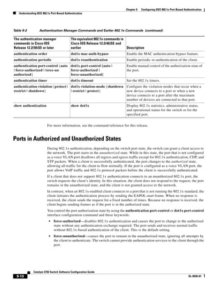
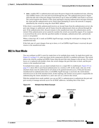

![9-14
Catalyst 3750 Switch Software Configuration Guide
OL-8550-07
Chapter 9 Configuring IEEE 802.1x Port-Based Authentication
Understanding IEEE 802.1x Port-Based Authentication
• Re-authentication fails.
The switch does not log 802.1x accounting information. Instead, it sends this information to the
RADIUS server, which must be configured to log accounting messages.
802.1x Accounting Attribute-Value Pairs
The information sent to the RADIUS server is represented in the form of Attribute-Value (AV) pairs.
These AV pairs provide data for different applications. (For example, a billing application might require
information that is in the Acct-Input-Octets or the Acct-Output-Octets attributes of a RADIUS packet.)
AV pairs are automatically sent by a switch that is configured for 802.1x accounting. Three types of
RADIUS accounting packets are sent by a switch:
• START–sent when a new user session starts
• INTERIM–sent during an existing session for updates
• STOP–sent when a session terminates
Table 9-3 lists the AV pairs and when they are sent are sent by the switch:
Table 9-3 Accounting AV Pairs
Attribute Number AV Pair Name START INTERIM STOP
Attribute[1] User-Name Always Always Always
Attribute[4] NAS-IP-Address Always Always Always
Attribute[5] NAS-Port Always Always Always
Attribute[8] Framed-IP-Address Never Sometimes1
1. The Framed-IP-Address AV pair is sent only if a valid Dynamic Host Control Protocol (DHCP) binding
exists for the host in the DHCP snooping bindings table.
Sometimes1
Attribute[25] Class Always Always Always
Attribute[30] Called-Station-ID Always Always Always
Attribute[31] Calling-Station-ID Always Always Always
Attribute[40] Acct-Status-Type Always Always Always
Attribute[41] Acct-Delay-Time Always Always Always
Attribute[42] Acct-Input-Octets Never Always Always
Attribute[43] Acct-Output-Octets Never Always Always
Attribute[44] Acct-Session-ID Always Always Always
Attribute[45] Acct-Authentic Always Always Always
Attribute[46] Acct-Session-Time Never Always Always
Attribute[49] Acct-Terminate-Cause Never Never Always
Attribute[61] NAS-Port-Type Always Always Always](https://image.slidesharecdn.com/2960scg-150701081942-lva1-app6891/85/Cisco-2960-Switch-Configuration-216-320.jpg)
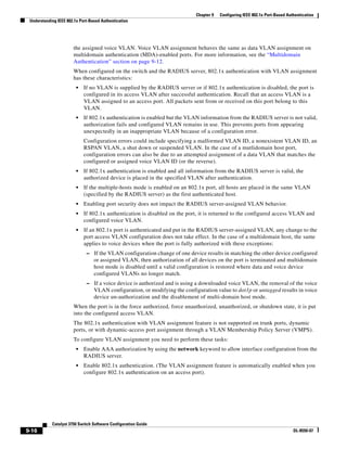
![9-17
Catalyst 3750 Switch Software Configuration Guide
OL-8550-07
Chapter 9 Configuring IEEE 802.1x Port-Based Authentication
Understanding IEEE 802.1x Port-Based Authentication
• Assign vendor-specific tunnel attributes in the RADIUS server. The RADIUS server must return
these attributes to the switch:
– [64] Tunnel-Type = VLAN
– [65] Tunnel-Medium-Type = 802
– [81] Tunnel-Private-Group-ID = VLAN name or VLAN ID
Attribute [64] must contain the value VLAN (type 13). Attribute [65] must contain the value 802
(type 6). Attribute [81] specifies the VLAN name or VLAN ID assigned to the 802.1x-authenticated
user.
For examples of tunnel attributes, see the “Configuring the Switch to Use Vendor-Specific RADIUS
Attributes” section on page 8-29.
For more configuration information, see the “Authentication Manager” section on page 9-8.
802.1x Authentication with Downloadable ACLs and Redirect URLs
You can download ACLs and redirect URLs from a RADIUS server to the switch during 802.1x
authentication or MAC authentication bypass of the host. You can also download ACLs during web
authentication.
Note A downloadable ACL is also referred to as a dACL.
If the host mode is single-host, MDA, or multiple-authentication mode, the switch modifies the source
address of the ACL to be the host IP address.
Note A port in multiple-host mode does not support the downloadable ACL and redirect URL feature.
You can apply the ACLs and redirect URLs to all the devices connected to the 802.1x-enabled port.
If no ACLs are downloaded during 802.1x authentication, the switch applies the static default ACL on
the port to the host. On a voice VLAN port, the switch applies the ACL only to the phone.
Note If a downloadable ACL or redirect URL is configured for a client on the authentication server, a default
port ACL on the connected client switch port must also be configured.
Cisco Secure ACS and Attribute-Value Pairs for the Redirect URL
The switch uses these cisco-av-pair VSAs:
• url-redirect is the HTTP to HTTPS URL.
• url-redirect-acl is the switch ACL name or number.
The switch uses the CiscoSecure-Defined-ACL AV pair to intercept an HTTP or HTTPS request from
the endpoint device. The switch then forwards the client web browser to the specified redirect address.
The url-redirect AV pair on the Cisco Secure ACS contains the URL to which the web browser is
redirected. The url-redirect-acl AV pair contains the name or number of an ACL that specifies the HTTP
or HTTPS traffic to redirect. Traffic that matches a permit ACE in the ACL is redirected.](https://image.slidesharecdn.com/2960scg-150701081942-lva1-app6891/85/Cisco-2960-Switch-Configuration-219-320.jpg)
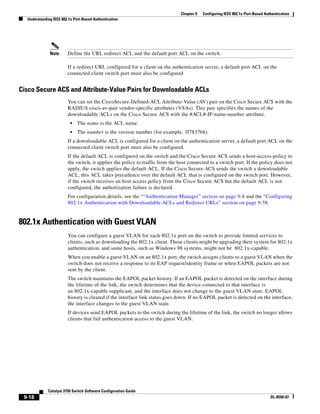
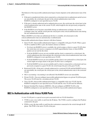
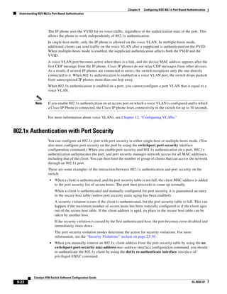
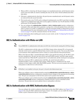
![9-24
Catalyst 3750 Switch Software Configuration Guide
OL-8550-07
Chapter 9 Configuring IEEE 802.1x Port-Based Authentication
Understanding IEEE 802.1x Port-Based Authentication
If 802.1x authentication times out while waiting for an EAPOL response from the client, the switch tries
to authorize the client by using MAC authentication bypass.
When the MAC authentication bypass feature is enabled on an 802.1x port, the switch uses the MAC
address as the client identity. The authentication server has a database of client MAC addresses that are
allowed network access. After detecting a client on an 802.1x port, the switch waits for an Ethernet
packet from the client. The switch sends the authentication server a RADIUS-access/request frame with
a username and password based on the MAC address. If authorization succeeds, the switch grants the
client access to the network. If authorization fails, the switch assigns the port to the guest VLAN if one
is configured.
If an EAPOL packet is detected on the interface during the lifetime of the link, the switch determines
that the device connected to that interface is an 802.1x-capable supplicant and uses 802.1x
authentication (not MAC authentication bypass) to authorize the interface. EAPOL history is cleared if
the interface link status goes down.
If the switch already authorized a port by using MAC authentication bypass and detects an 802.1x
supplicant, the switch does not unauthorize the client connected to the port. When re-authentication
occurs, the switch uses 802.1x authentication as the preferred re-authentication process if the previous
session ended because the Termination-Action RADIUS attribute value is DEFAULT.
Clients that were authorized with MAC authentication bypass can be re-authenticated. The
re-authentication process is the same as that for clients that were authenticated with 802.1x. During
re-authentication, the port remains in the previously assigned VLAN. If re-authentication is successful,
the switch keeps the port in the same VLAN. If re-authentication fails, the switch assigns the port to the
guest VLAN, if one is configured.
If re-authentication is based on the Session-Timeout RADIUS attribute (Attribute[27]) and the
Termination-Action RADIUS attribute (Attribute [29]) and if the Termination-Action RADIUS attribute
(Attribute [29]) action is Initialize, (the attribute value is DEFAULT), the MAC authentication bypass
session ends, and connectivity is lost during re-authentication. If MAC authentication bypass is enabled
and the 802.1x authentication times out, the switch uses the MAC authentication bypass feature to
initiate re-authorization. For more information about these AV pairs, see RFC 3580, “802.1X Remote
Authentication Dial In User Service (RADIUS) Usage Guidelines.”
MAC authentication bypass interacts with the features:
• 802.1x authentication—You can enable MAC authentication bypass only if 802.1x authentication is
enabled on the port.
• Guest VLAN—If a client has an invalid MAC address identity, the switch assigns the client to a
guest VLAN if one is configured.
• Restricted VLAN—This feature is not supported when the client connected to an 802.lx port is
authenticated with MAC authentication bypass.
• Port security—See the “802.1x Authentication with Port Security” section on page 9-22.
• Voice VLAN—See the “802.1x Authentication with Voice VLAN Ports” section on page 9-21.
• VLAN Membership Policy Server (VMPS)—802.1x and VMPS are mutually exclusive.
• Private VLAN—You can assign a client to a private VLAN.
For more configuration information, see the “Authentication Manager” section on page 9-8.](https://image.slidesharecdn.com/2960scg-150701081942-lva1-app6891/85/Cisco-2960-Switch-Configuration-226-320.jpg)
![9-25
Catalyst 3750 Switch Software Configuration Guide
OL-8550-07
Chapter 9 Configuring IEEE 802.1x Port-Based Authentication
Understanding IEEE 802.1x Port-Based Authentication
Network Admission Control Layer 2 802.1x Validation
Note To use Network Admission Control, the switch must be running the LAN base image.
The switch supports the Network Admission Control (NAC) Layer 2 802.1x validation, which checks
the antivirus condition or posture of endpoint systems or clients before granting the devices network
access. With NAC Layer 2 802.1x validation, you can do these tasks:
• Download the Session-Timeout RADIUS attribute (Attribute[27]) and the Termination-Action
RADIUS attribute (Attribute[29]) from the authentication server.
• Set the number of seconds between re-authentication attempts as the value of the Session-Timeout
RADIUS attribute (Attribute[27]) and get an access policy against the client from the RADIUS
server.
• Set the action to be taken when the switch tries to re-authenticate the client by using the
Termination-Action RADIUS attribute (Attribute[29]). If the value is the DEFAULT or is not set, the
session ends. If the value is RADIUS-Request, the re-authentication process starts.
• View the NAC posture token, which shows the posture of the client, by using the show
authentication or show dot1x privileged EXEC command.
• Configure secondary private VLANs as guest VLANs.
Configuring NAC Layer 2 802.1x validation is similar to configuring 802.1x port-based authentication
except that you must configure a posture token on the RADIUS server. For information about
configuring NAC Layer 2 802.1x validation, see the “Configuring NAC Layer 2 802.1x Validation”
section on page 9-55 and the “Configuring Periodic Re-Authentication” section on page 9-42.
For more information about NAC, see the Network Admission Control Software Configuration Guide.
For more configuration information, see the “Authentication Manager” section on page 9-8.
Flexible Authentication Ordering
You can use flexible authentication ordering to configure the order of methods that a port uses to
authenticate a new host. MAC authentication bypass and 802.1x can be the primary or secondary
authentication methods, and web authentication can be the fallback method if either or both of those
authentication attempts fail. For more information see the “Configuring Flexible Authentication
Ordering” section on page 9-60.
Open1x Authentication
Open1x authentication allows a device access to a port before that device is authenticated. When open
authentication is configured, a new host on the port can only send traffic to the switch. After the host is
authenticated, the policies configured on the RADIUS server are applied to that host.
You can configure open authentication with these scenarios:
• Single-host mode with open authentication–Only one user is allowed network access before and
after authentication.
• MDA mode with open authentication–Only one user in the voice domain and one user in the data
domain are allowed.](https://image.slidesharecdn.com/2960scg-150701081942-lva1-app6891/85/Cisco-2960-Switch-Configuration-227-320.jpg)
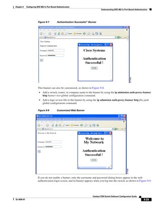
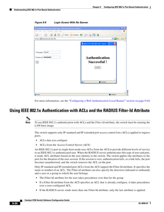
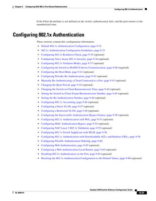
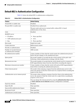
![9-33
Catalyst 3750 Switch Software Configuration Guide
OL-8550-07
Chapter 9 Configuring IEEE 802.1x Port-Based Authentication
Configuring 802.1x Authentication
802.1x Authentication Configuration Guidelines
These section has configuration guidelines for these features:
• 802.1x Authentication, page 9-33
• VLAN Assignment, Guest VLAN, Restricted VLAN, and Inaccessible Authentication Bypass,
page 9-34
• MAC Authentication Bypass, page 9-35
• Maximum Number of Allowed Devices Per Port, page 9-35
802.1x Authentication
These are the 802.1x authentication configuration guidelines:
• When IEEE 802.1x authentication is enabled, ports are authenticated before any other Layer 2
feature is enabled.
• If you try to change the mode of an 802.1x-enabled port (for example, from access to trunk), an error
message appears, and the port mode is not changed.
• If the VLAN to which an 802.1x-enabled port is assigned changes, this change is transparent and
does not affect the switch. For example, this change occurs if a port is assigned to a RADIUS
server-assigned VLAN and is then assigned to a different VLAN after re-authentication.
If the VLAN to which an 802.1x port is assigned to shut down, disabled, or removed, the port
becomes unauthorized. For example, the port is unauthorized after the access VLAN to which a port
is assigned shuts down or is removed.
• The IEEE 802.1x protocol is supported on Layer 2 static-access ports and voice VLAN ports, but it
is not supported on these port types:
– Trunk port—If you try to enable 802.1x authentication on a trunk port, an error message
appears, and 802.1x authentication is not enabled. If you try to change the mode of
an 802.1x-enabled port to trunk, an error message appears, and the port mode is not changed.
– Dynamic ports—A port in dynamic mode can negotiate with its neighbor to become a trunk
port. If you try to enable 802.1x authentication on a dynamic port, an error message appears,
and 802.1x authentication is not enabled. If you try to change the mode of an 802.1x-enabled
port to dynamic, an error message appears, and the port mode is not changed.
– Dynamic-access ports—If you try to enable 802.1x authentication on a dynamic-access (VLAN
Query Protocol [VQP]) port, an error message appears, and 802.1x authentication is not
enabled. If you try to change an 802.1x-enabled port to dynamic VLAN assignment, an error
message appears, and the VLAN configuration is not changed.
– EtherChannel port—Do not configure a port that is an active or a not-yet-active member of an
EtherChannel as an 802.1x port. If you try to enable 802.1x authentication on an EtherChannel
port, an error message appears, and 802.1x authentication is not enabled.
MAC authentication bypass Disabled.
Voice-aware security Disabled
Table 9-4 Default 802.1x Authentication Configuration (continued)
Feature Default Setting](https://image.slidesharecdn.com/2960scg-150701081942-lva1-app6891/85/Cisco-2960-Switch-Configuration-235-320.jpg)
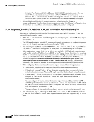
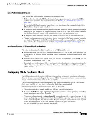
![9-36
Catalyst 3750 Switch Software Configuration Guide
OL-8550-07
Chapter 9 Configuring IEEE 802.1x Port-Based Authentication
Configuring 802.1x Authentication
• The readiness check can be sent on a port that handles multiple hosts (for example, a PC that is
connected to an IP phone). A syslog message is generated for each of the clients that respond to the
readiness check within the timer period.
Beginning in privileged EXEC mode, follow these steps to enable the 802.1x readiness check on the
switch:
This example shows how to enable a readiness check on a switch to query a port. It also shows the
response received from the queried port verifying that the device connected to it is 802.1x-capable:
switch# dot1x test eapol-capable interface gigabitethernet0/13
DOT1X_PORT_EAPOL_CAPABLE:DOT1X: MAC 00-01-02-4b-f1-a3 on gigabitethernet0/13 is EAPOL
capable
Configuring Voice Aware 802.1x Security
Note To use voice aware IEEE 802.1x authentication, the switch must be running the LAN base image.
You use the voice aware 802.1x security feature on the switch to disable only the VLAN on which a
security violation occurs, whether it is a data or voice VLAN. You can use this feature in IP phone
deployments where a PC is connected to the IP phone. A security violation found on the data VLAN
results in the shutdown of only the data VLAN. The traffic on the voice VLAN flows through the switch
without interruption.
Follow these guidelines to configure voice aware 802.1x voice security on the switch:
• You enable voice aware 802.1x security by entering the errdisable detect cause security-violation
shutdown vlan global configuration command. You disable voice aware 802.1x security by entering
the no version of this command. This command applies to all 802.1x-configured ports in the switch.
Note If you do not include the shutdown vlan keywords, the entire port is shut down when it enters the
error-disabled state.
Command Purpose
Step 1 dot1x test eapol-capable [interface
interface-id]
Enable the 802.1x readiness check on the switch.
(Optional) For interface-id specify the port on which to check for 802.1x
readiness.
Note If you omit the optional interface keyword, all interfaces on the
switch are tested.
Step 1 configure terminal (Optional) Enter global configuration mode.
Step 2 dot1x test timeout timeout (Optional) Configure the timeout used to wait for EAPOL response. The
range is from 1 to 65535 seconds. The default is 10 seconds.
Step 3 end (Optional) Return to privileged EXEC mode.
Step 4 show running-config (Optional) Verify your modified timeout values.](https://image.slidesharecdn.com/2960scg-150701081942-lva1-app6891/85/Cisco-2960-Switch-Configuration-238-320.jpg)
![9-37
Catalyst 3750 Switch Software Configuration Guide
OL-8550-07
Chapter 9 Configuring IEEE 802.1x Port-Based Authentication
Configuring 802.1x Authentication
• If you use the errdisable recovery cause security-violation global configuration command to
configure error-disabled recovery, the port is automatically re-enabled. If error-disabled recovery is
not configured for the port, you re-enable it by using the shutdown and no-shutdown interface
configuration commands.
• You can re-enable individual VLANs by using the clear errdisable interface interface-id vlan
[vlan-list] privileged EXEC command. If you do not specify a range, all VLANs on the port are
enabled.
Beginning in privileged EXEC mode, follow these steps to enable voice aware 802.1x security:
This example shows how to configure the switch to shut down any VLAN on which a security violation
error occurs:
Switch(config)# errdisable detect cause security-violation shutdown vlan
This example shows how to re-enable all VLANs that were error disabled on port Gigabit Ethernet 0/2.
Switch# clear errdisable interface gigabitethernet0/2 vlan
You can verify your settings by entering the show errdisable detect privileged EXEC command.
Configuring 802.1x Violation Modes
Note To configure violation modes, the switch must be running the LAN base image.
You can configure an 802.1x port so that it shuts down, generates a syslog error, or discards packets from
a new device when:
• a device connects to an 802.1x-enable port
Command Purpose
Step 1 configure terminal Enter global configuration mode.
Step 2 errdisable detect cause
security-violation shutdown vlan
Shut down any VLAN on which a security violation error occurs.
Note If the shutdown vlan keywords are not included, the entire port
enters the error-disabled state and shuts down.
Step 3 errdisable recovery cause
security-violation
(Optional) Enable automatic per-VLAN error recovery.
Step 4 clear errdisable interface interface-id
vlan [vlan-list]
(Optional) Reenable individual VLANs that have been error disabled.
• For interface-id specify the port on which to reenable individual
VLANs.
• (Optional) For vlan-list specify a list of VLANs to be re-enabled. If
vlan-list is not specified, all VLANs are re-enabled.
Step 5 shutdown
no-shutdown
(Optional) Re-enable an error-disabled VLAN, and clear all error-disable
indications.
Step 6 end Return to privileged EXEC mode.
Step 7 show errdisable detect Verify your entries.
Step 8 copy running-config startup-config (Optional) Save your entries in the configuration file.](https://image.slidesharecdn.com/2960scg-150701081942-lva1-app6891/85/Cisco-2960-Switch-Configuration-239-320.jpg)
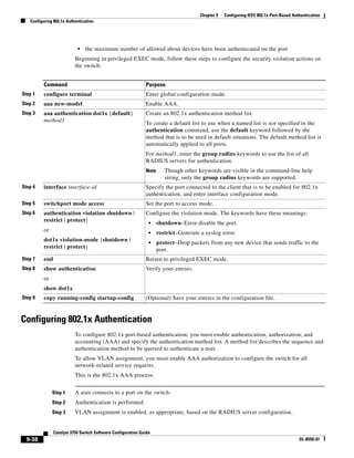
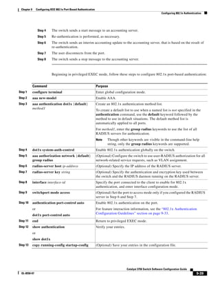
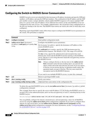
![9-41
Catalyst 3750 Switch Software Configuration Guide
OL-8550-07
Chapter 9 Configuring IEEE 802.1x Port-Based Authentication
Configuring 802.1x Authentication
You also need to configure some settings on the RADIUS server. These settings include the IP address
of the switch and the key string to be shared by both the server and the switch. For more information,
see the RADIUS server documentation.
Configuring the Host Mode
Beginning in privileged EXEC mode, follow these steps to allow a single host (client) or multiple hosts
on an 802.1x-authorized port that has the dot1x port-control interface configuration command set to
auto. Use the multi-domain keyword to configure multidomain authentication (MDA) to enable
authentication of both a host and a voice device, such as an IP phone (Cisco or non-Cisco) on the same
switch port. This procedure is optional.
Command Purpose
Step 1 configure terminal Enter global configuration mode.
Step 2 radius-server vsa send authentication Configure the network access server to recognize and use vendor-specific
attributes (VSAs).
Step 3 interface interface-id Specify the port to which multiple hosts are indirectly attached, and enter
interface configuration mode.
Step 4 authentication host-mode [multi-auth |
multi-domain | multi-host |
single-host]
or
dot1x host-mode {single-host |
multi-host | multi-domain}
The keywords have these meanings:
• multi-auth–Allow one client on the voice VLAN and multiple
authenticated clients on the data VLAN.
Note The multi-auth keyword is only available with the
authentication host-mode command.
• multi-host–Allow multiple hosts on an 802.1x-authorized port after
a single host has been authenticated.
• multi-domain–Allow both a host and a voice device, such as an IP
phone (Cisco or non-Cisco), to be authenticated on
an 802.1x-authorized port.
Note You must configure the voice VLAN for the IP phone when the
host mode is set to multi-domain. For more information, see
Chapter 14, “Configuring Voice VLAN.”
• single-host–Allow a single host (client) on an 802.1x-authorized
port.
Make sure that the authentication port-control or dot1x port-control
interface configuration command set is set to auto for the specified
interface.
Step 5 switchport voice vlan vlan-id (Optional) Configure the voice VLAN.
Step 6 end Return to privileged EXEC mode.
Step 7 show authentication interface
interface-id
or
show dot1x interface interface-id
Verify your entries.
Step 8 copy running-config startup-config (Optional) Save your entries in the configuration file.](https://image.slidesharecdn.com/2960scg-150701081942-lva1-app6891/85/Cisco-2960-Switch-Configuration-243-320.jpg)
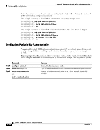
![9-43
Catalyst 3750 Switch Software Configuration Guide
OL-8550-07
Chapter 9 Configuring IEEE 802.1x Port-Based Authentication
Configuring 802.1x Authentication
To disable periodic re-authentication, use the no authentication periodic or the no dot1x
reauthentication interface configuration command. To return to the default number of seconds between
re-authentication attempts, use the no authentication timer or the no dot1x timeout reauth-period
interface configuration command.
This example shows how to enable periodic re-authentication and set the number of seconds between
re-authentication attempts to 4000:
Switch(config-if)# dot1x reauthentication
Switch(config-if)# dot1x timeout reauth-period 4000
Manually Re-Authenticating a Client Connected to a Port
You can manually re-authenticate the client connected to a specific port at any time by entering the dot1x
re-authenticate interface interface-id privileged EXEC command. This step is optional. If you want to
enable or disable periodic re-authentication, see the “Configuring Periodic Re-Authentication” section
on page 9-42.
This example shows how to manually re-authenticate the client connected to a port:
Switch# dot1x re-authenticate interface gigabitethernet0/1
Step 4 authentication timer {{[inactivity |
reauthenticate] [server | am]} {restart
value}}
or
dot1x timeout reauth-period {seconds |
server}
Set the number of seconds between re-authentication attempts.
The authentication timer keywords have these meanings:
• inactivity—Interval in seconds after which if there is no activity from
the client then it is unauthorized
• reauthenticate—Time in seconds after which an automatic
re-authentication attempt is be initiated
• server am—Interval in seconds after which an attempt is made to
authenticate an unauthorized port
• restart value—Interval in seconds after which an attempt is made to
authenticate an unauthorized port
The dot1x timeout reauth-period keywords have these meanings:
• seconds—Sets the number of seconds from 1 to 65535; the default is
3600 seconds.
• server—Sets the number of seconds based on the value of the
Session-Timeout RADIUS attribute (Attribute[27]) and the
Termination-Action RADIUS attribute (Attribute [29]).
This command affects the behavior of the switch only if periodic
re-authentication is enabled.
Step 5 end Return to privileged EXEC mode.
Step 6 show authentication interface-id
or
show dot1x interface interface-id
Verify your entries.
Step 7 copy running-config startup-config (Optional) Save your entries in the configuration file.
Command Purpose](https://image.slidesharecdn.com/2960scg-150701081942-lva1-app6891/85/Cisco-2960-Switch-Configuration-245-320.jpg)
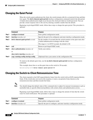
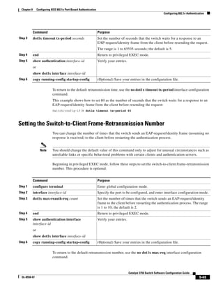
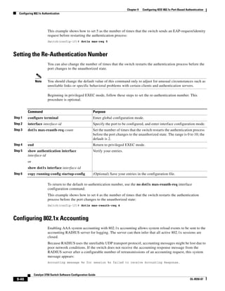
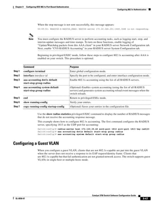
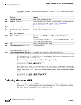
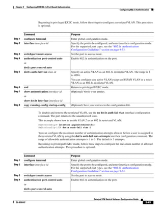
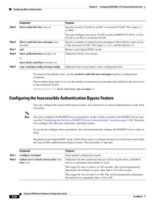
![9-51
Catalyst 3750 Switch Software Configuration Guide
OL-8550-07
Chapter 9 Configuring IEEE 802.1x Port-Based Authentication
Configuring 802.1x Authentication
Step 3 radius-server deadtime minutes (Optional) Set the number of minutes that a RADIUS server is not sent
requests. The range is from 0 to 1440 minutes (24 hours). The default is
0 minutes.
Step 4 radius-server host ip-address
[acct-port udp-port] [auth-port
udp-port] [test username name
[idle-time time] [ignore-acct-port]
[ignore-auth-port]] [key string]
(Optional) Configure the RADIUS server parameters by using these
keywords:
• acct-port udp-port—Specify the UDP port for the RADIUS
accounting server. The range for the UDP port number is from 0 to
65536. The default is 1646.
• auth-port udp-port—Specify the UDP port for the RADIUS
authentication server. The range for the UDP port number is from 0
to 65536. The default is 1645.
Note You should configure the UDP port for the RADIUS accounting
server and the UDP port for the RADIUS authentication server to
nondefault values.
• test username name—Enable automated testing of the RADIUS
server status, and specify the username to be used.
• idle-time time—Set the interval of time in minutes after which the
switch sends test packets to the server. The range is from 1 to
35791 minutes. The default is 60 minutes (1 hour).
• ignore-acct-port—Disable testing on the RADIUS-server
accounting port.
• ignore-auth-port—Disable testing on the RADIUS-server
authentication port.
• key string—Specify the authentication and encryption key for all
RADIUS communication between the switch and the RADIUS
daemon.
Note Always configure the key as the last item in the radius-server
host command syntax because leading spaces are ignored, but
spaces within and at the end of the key are used. If you use spaces
in the key, do not enclose the key in quotation marks unless the
quotation marks are part of the key. This key must match the
encryption used on the RADIUS daemon.
You can also configure the authentication and encryption key by
using the radius-server key {0 string | 7 string | string} global
configuration command.
Step 5 dot1x critical {eapol | recovery delay
milliseconds}
(Optional) Configure the parameters for inaccessible authentication
bypass:
eapol—Specify that the switch sends an EAPOL-Success message when
the switch successfully authenticates the critical port.
recovery delay milliseconds—Set the recovery delay period during
which the switch waits to re-initialize a critical port when a RADIUS
server that was unavailable becomes available. The range is from 1 to
10000 milliseconds. The default is 1000 milliseconds (a port can be
re-initialized every second).
Command Purpose](https://image.slidesharecdn.com/2960scg-150701081942-lva1-app6891/85/Cisco-2960-Switch-Configuration-253-320.jpg)
![9-52
Catalyst 3750 Switch Software Configuration Guide
OL-8550-07
Chapter 9 Configuring IEEE 802.1x Port-Based Authentication
Configuring 802.1x Authentication
To return to the RADIUS server default settings, use the no radius-server dead-criteria, the no
radius-server deadtime, and the no radius-server host global configuration commands. To return to
the default settings of inaccessible authentication bypass, use the no dot1x critical {eapol | recovery
delay} global configuration command. To disable inaccessible authentication bypass, use the no dot1x
critical interface configuration command.
This example shows how to configure the inaccessible authentication bypass feature:
Switch(config)# radius-server dead-criteria time 30 tries 20
Switch(config)# radius-server deadtime 60
Switch(config)# radius-server host 1.1.1.2 acct-port 1550 auth-port 1560 test username
user1 idle-time 30 key abc1234
Switch(config)# dot1x critical eapol
Switch(config)# dot1x critical recovery delay 2000
Switch(config)# interface gigabitethernet 0/1
Switch(config)# radius-server deadtime 60
Switch(config-if)# dot1x critical
Switch(config-if)# dot1x critical recovery action reinitialize
Switch(config-if)# dot1x critical vlan 20
Switch(config-if)# end
Configuring 802.1x Authentication with WoL
Beginning in privileged EXEC mode, follow these steps to enable 802.1x authentication with WoL. This
procedure is optional.
Step 6 interface interface-id Specify the port to be configured, and enter interface configuration mode.
For the supported port types, see the “802.1x Authentication
Configuration Guidelines” section on page 9-33.
Step 7 dot1x critical [recovery action
reinitialize | vlan vlan-id]
Enable the inaccessible authentication bypass feature, and use these
keywords to configure the feature:
• recovery action reinitialize—Enable the recovery feature, and
specify that the recovery action is to authenticate the port when an
authentication server is available.
• vlan vlan-id—Specify the access VLAN to which the switch can
assign a critical port. The range is from 1 to 4094.
Step 8 end Return to privileged EXEC mode.
Step 9 show authentication interface
interface-id
or
show dot1x interface interface-id
(Optional) Verify your entries.
Step 10 copy running-config startup-config (Optional) Save your entries in the configuration file.
Command Purpose
Command Purpose
Step 1 configure terminal Enter global configuration mode.
Step 2 interface interface-id Specify the port to be configured, and enter interface configuration mode.
For the supported port types, see the “802.1x Authentication
Configuration Guidelines” section on page 9-33.](https://image.slidesharecdn.com/2960scg-150701081942-lva1-app6891/85/Cisco-2960-Switch-Configuration-254-320.jpg)
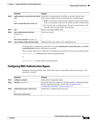
![9-54
Catalyst 3750 Switch Software Configuration Guide
OL-8550-07
Chapter 9 Configuring IEEE 802.1x Port-Based Authentication
Configuring 802.1x Authentication
To disable MAC authentication bypass, use the no dot1x mac-auth-bypass interface configuration
command.
This example shows how to enable MAC authentication bypass:
Switch(config-if)# dot1x mac-auth-bypass
Configuring NAC Layer 2 802.1x Validation
You can configure NAC Layer 2 802.1x validation, which is also referred to as 802.1x authentication
with a RADIUS server.
Beginning in privileged EXEC mode, follow these steps to configure NAC Layer 2 802.1x validation.
The procedure is optional.
Step 4 dot1x mac-auth-bypass [eap | timeout
activity {value}]
Enable MAC authentication bypass.
(Optional) Use the eap keyword to configure the switch to use EAP for
authorization.
(Optional) Use the timeout activity keywords to configured the number
of seconds that a connected host can be inactive before it is placed in an
unauthorized state. The range is 1 to 65535.
You must enable port security before configuring a time out value. For
more information, see the “Configuring Port Security” section on
page 22-8.
Step 5 end Return to privileged EXEC mode.
Step 6 show authentication interface-id
or
show dot1x interface interface-id
Verify your entries.
Step 7 copy running-config startup-config (Optional) Save your entries in the configuration file.
Command Purpose
Command Purpose
Step 1 configure terminal Enter global configuration mode.
Step 2 interface interface-id Specify the port to be configured, and enter interface configuration mode.
Step 3 dot1x guest-vlan vlan-id Specify an active VLAN as an 802.1x guest VLAN. The range is 1 to
4094.
You can configure any active VLAN except an RSPAN VLAN, or a voice
VLAN as an 802.1x guest VLAN.
Step 4 authentication periodic
or
dot1x reauthentication
Enable periodic re-authentication of the client, which is disabled by
default.](https://image.slidesharecdn.com/2960scg-150701081942-lva1-app6891/85/Cisco-2960-Switch-Configuration-256-320.jpg)
![9-55
Catalyst 3750 Switch Software Configuration Guide
OL-8550-07
Chapter 9 Configuring IEEE 802.1x Port-Based Authentication
Configuring 802.1x Authentication
This example shows how to configure NAC Layer 2 802.1x validation:
Switch# configure terminal
Switch(config)# interface gigabitethernet0/1
Switch(config-if)# dot1x reauthentication
Switch(config-if)# dot1x timeout reauth-period server
Configuring 802.1x Switch Supplicant with NEAT
Configuring this feature requires that one switch (outside a wiring closet) is configured as supplicant and
is connected to an authenticator switch.
Note You cannot enable MDA or multiauth mode on the authenticator switch interface that connects
to one more supplicant switches.
For overview information, see the “802.1x Switch Supplicant with Network Edge Access Topology
(NEAT)” section on page 9-26.
Note The cisco-av-pairs must be configured as device-traffic-class=switch on the ACS, which sets the
interface as a trunk after the supplicant is successfuly authenticated.
Beginning in privileged EXEC mode, follow these steps to configure a switch as an authenticator:
Step 5 dot1x timeout reauth-period {seconds |
server}
Set the number of seconds between re-authentication attempts.
The keywords have these meanings:
• seconds—Sets the number of seconds from 1 to 65535; the default is
3600 seconds.
• server—Sets the number of seconds based on the value of the
Session-Timeout RADIUS attribute (Attribute[27]) and the
Termination-Action RADIUS attribute (Attribute [29]).
This command affects the behavior of the switch only if periodic
re-authentication is enabled.
Step 6 end Return to privileged EXEC mode.
Step 7 show authentication interface
interface-id
or
show dot1x interface interface-id
Verify your 802.1x authentication configuration.
Step 8 copy running-config startup-config (Optional) Save your entries in the configuration file.
Command Purpose
Command Purpose
Step 1 configure terminal Enter global configuration mode.
Step 2 cisp enable Enable CISP.](https://image.slidesharecdn.com/2960scg-150701081942-lva1-app6891/85/Cisco-2960-Switch-Configuration-257-320.jpg)
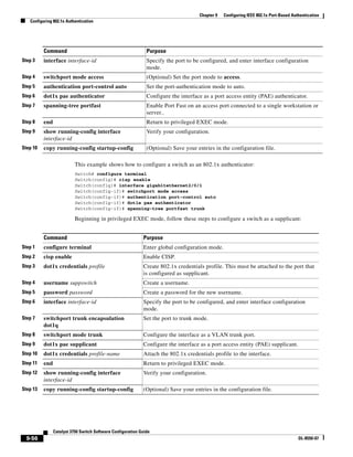
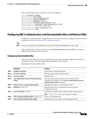
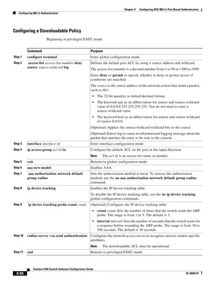
![9-59
Catalyst 3750 Switch Software Configuration Guide
OL-8550-07
Chapter 9 Configuring IEEE 802.1x Port-Based Authentication
Configuring 802.1x Authentication
This example shows how to configure a switch for a downloadable policy:
Switch# config terminal
Enter configuration commands, one per line. End with CNTL/Z.
Switch(config)# aaa new-model
Switch(config)# aaa authorization network default group radius
Switch(config)# ip device tracking
Switch(config)# ip access-list extended default_acl
Switch(config-ext-nacl)# permit ip any any
Switch(config-ext-nacl)# exit
Switch(config)# radius-server vsa send authentication
Switch(config)# int fastEthernet 2/13
Switch(config-if)# ip access-group default_acl in
Switch(config-if)# exit
Configuring Flexible Authentication Ordering
Beginning in privileged EXEC mode, follow these steps:
This example shows how to configure a port attempt 802.1x authentication first, followed by web
authentication as fallback method:
Switch# configure terminal
Switch(config)# interface gigabitethernet 1/0/1
Switch(config)# authentication order dot1x webauth
Step 12 show ip device tracking all Displays information about the entries in the IP device tracking table.
Step 13 copy running-config startup-config (Optional) Saves your entries in the configuration file.
Command Purpose
Command Purpose
Step 1 configure terminal Enter global configuration mode.
Step 2 interface interface-id Specify the port to be configured, and enter interface
configuration mode.
Step 3 authentication order [dot1x | mab] |
{webauth}
(Optional) Set the order of authentication methods used on a port.
Step 4 authentication priority [dot1x | mab] |
{webauth}
(Optional) Add an authentication method to the port-priority list.
Step 5 show authentication (Optional) Verify your entries.
Step 6 copy running-config startup-config (Optional) Save your entries in the configuration file.](https://image.slidesharecdn.com/2960scg-150701081942-lva1-app6891/85/Cisco-2960-Switch-Configuration-261-320.jpg)
![9-60
Catalyst 3750 Switch Software Configuration Guide
OL-8550-07
Chapter 9 Configuring IEEE 802.1x Port-Based Authentication
Configuring 802.1x Authentication
Configuring Open1x
Beginning in privileged EXEC mode:
This example shows how to configure open 1x on a port:
Switch# configure terminal
Switch(config)# interface gigabitethernet 1/0/1
Switch(config)# authentication control-direction both
Switch(config)# autentication fallback profile1
Switch(config)# authentication host-mode multi-auth
Switch(config)# authentication open
Switch(config)# authentication order dot1x webauth
Switch(config)# authentication periodic
Switch(config)# authentication port-control auto
Command Purpose
Step 1 configure terminal Enter global configuration mode.
Step 2 interface interface-id Specify the port to be configured, and enter interface
configuration mode.
Step 3 authentication control-direction {both | in} (Optional) Configure the port control as unidirectional or
bidirectional.
Step 4 authentication fallback name (Optional) Configure a port to use web authentication as a
fallback method for clients that do not support 802.1x
authentication.
Step 5 authentication host-mode [multi-auth |
multi-domain | multi-host | single-host]
(Optional) Set the authorization manager mode on a port.
Step 6 authentication open (Optional) Enable or disable open access on a port.
Step 7 authentication order [dot1x | mab] |
{webauth}
(Optional) Set the order of authentication methods used on a port.
Step 8 authentication periodic (Optional) Enable or disable reauthentication on a port.
Step 9 authentication port-control {auto |
force-authorized | force-un authorized}
(Optional) Enable manual control of the port authorization state.
Step 10 show authentication (Optional) Verify your entries.
Step 11 copy running-config startup-config (Optional) Save your entries in the configuration file.](https://image.slidesharecdn.com/2960scg-150701081942-lva1-app6891/85/Cisco-2960-Switch-Configuration-262-320.jpg)
![9-61
Catalyst 3750 Switch Software Configuration Guide
OL-8550-07
Chapter 9 Configuring IEEE 802.1x Port-Based Authentication
Configuring 802.1x Authentication
Configuring Web Authentication
Note To configure Web Authentication, the switch must be running the LAN base image.
Beginning in privileged EXEC mode, follow these steps to configure authentication, authorization,
accounting (AAA) and RADIUS on a switch before configuring web authentication. The steps enable
AAA by using RADIUS authentication and enable device tracking.
This example shows how to enable AAA, use RADIUS authentication and enable device tracking:
Switch(config) configure terminal
Switch(config)# aaa new-model
Switch(config)# aaa authentication login default group radius
Switch(config)# aaa authorization auth-proxy default group radius
Switch(config)# radius-server host 1.1.1.2 key key1
Switch(config)# radius-server attribute 8 include-in-access-req
Switch(config)# radius-server vsa send authentication
Command Purpose
Step 1 configure terminal Enter global configuration mode.
Step 2 aaa new-model Enable AAA.
Step 3 aaa authentication login default group
radius
Use RADIUS authentication. Before you can use this authentication
method, you must configure the RADIUS server. For more
information, see Chapter 8, “Configuring Switch-Based
Authentication.”
The console prompts you for a username and password on future
attempts to access the switch console after entering the aaa
authentication login command. If you do not want to be prompted for
a username and password, configure a second login authentication
list:
Switch# config t
Switch(config)# aaa authentication login line-console none
Switch(config)# line console 0
Switch(config-line)# login authentication line-console
Switch(config-line)# end
Step 4 aaa authorization auth-proxy default
group radius
Use RADIUS for authentication-proxy (auth-proxy) authorization.
Step 5 radius-server host key radius-key Specify the authentication and encryption key for RADIUS
communication between the switch and the RADIUS daemon.
Step 6 radius-server attribute 8
include-in-access-req
Configure the switch to send the Framed-IP-Address RADIUS
attribute (Attribute[8]) in access-request or accounting-request
packets.
Step 7 radius-server vsa send authentication Configure the network access server to recognize and use
vendor-specific attributes (VSAs).
Step 8 ip device tracking Enable the IP device tracking table.
To disable the IP device tracking table, use the no ip device tracking
global configuration commands.
Step 9 end Return to privileged EXEC mode.](https://image.slidesharecdn.com/2960scg-150701081942-lva1-app6891/85/Cisco-2960-Switch-Configuration-263-320.jpg)
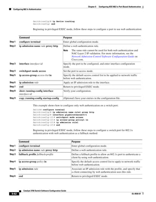
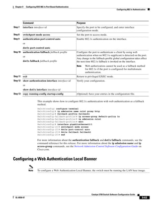
![9-64
Catalyst 3750 Switch Software Configuration Guide
OL-8550-07
Chapter 9 Configuring IEEE 802.1x Port-Based Authentication
Configuring 802.1x Authentication
Beginning in privileged EXEC mode, follow these steps to configure a local banner on a switch that has
web authentication configured.
This example shows how to configure a local banner with the custom message My Switch:
Switch(config) configure terminal
Switch(config)# aaa new-model
Switch(config)# aaa ip auth-proxy auth-proxy-banner C My Switch C
Switch(config) end
For more information about the ip auth-proxy auth-proxy-banner command, see the “Authentication
Proxy Commands” section of the Cisco IOS Security Command Reference on Cisco.com.
Disabling 802.1x Authentication on the Port
You can disable 802.1x authentication on the port by using the no dot1x pae interface configuration
command.
Beginning in privileged EXEC mode, follow these steps to disable 802.1x authentication on the port.
This procedure is optional.
To configure the port as an 802.1x port access entity (PAE) authenticator, which enables 802.1x on the
port but does not allow clients connected to the port to be authorized, use the dot1x pae authenticator
interface configuration command.
This example shows how to disable 802.1x authentication on the port:
Switch(config)# interface gigabitethernet0/1
Switch(config-if)# no dot1x pae authenticator
Command Purpose
Step 1 configure terminal Enter global configuration mode.
Step 2 ip admission auth-proxy-banner http
[banner-text | file-path]
Enable the local banner.
(Optional) Create a custom banner by entering C banner-text C, where
C is a delimiting character or file-path indicates a file (for example, a logo
or text file) that appears in the banner.
Step 3 end Return to privileged EXEC mode.
Command Purpose
Step 1 configure terminal Enter global configuration mode.
Step 2 interface interface-id Specify the port to be configured, and enter interface configuration mode.
Step 3 no dot1x pae Disable 802.1x authentication on the port.
Step 4 end Return to privileged EXEC mode.
Step 5 show authentication interface-id
or
show dot1x interface interface-id
Verify your entries.
Step 6 copy running-config startup-config (Optional) Save your entries in the configuration file.](https://image.slidesharecdn.com/2960scg-150701081942-lva1-app6891/85/Cisco-2960-Switch-Configuration-266-320.jpg)
![9-65
Catalyst 3750 Switch Software Configuration Guide
OL-8550-07
Chapter 9 Configuring IEEE 802.1x Port-Based Authentication
Displaying 802.1x Statistics and Status
Resetting the 802.1x Authentication Configuration to the Default Values
Beginning in privileged EXEC mode, follow these steps to reset the 802.1x authentication configuration
to the default values. This procedure is optional.
Displaying 802.1x Statistics and Status
To display 802.1x statistics for all ports, use the show dot1x all statistics privileged EXEC command.
To display 802.1x statistics for a specific port, use the show dot1x statistics interface interface-id
privileged EXEC command.
To display the 802.1x administrative and operational status for the switch, use the show dot1x all
[details | statistics | summary] privileged EXEC command. To display the 802.1x administrative and
operational status for a specific port, use the show dot1x interface interface-id privileged EXEC
command.
For detailed information about the fields in these displays, see the command reference for this release.
Command Purpose
Step 1 configure terminal Enter global configuration mode.
Step 2 interface interface-id Enter interface configuration mode, and specify the port to be configured.
Step 3 dot1x default Reset the 802.1x parameters to the default values.
Step 4 end Return to privileged EXEC mode.
Step 5 show authentication interface
interface-id
or
show dot1x interface interface-id
Verify your entries.
Step 6 copy running-config startup-config (Optional) Save your entries in the configuration file.](https://image.slidesharecdn.com/2960scg-150701081942-lva1-app6891/85/Cisco-2960-Switch-Configuration-267-320.jpg)

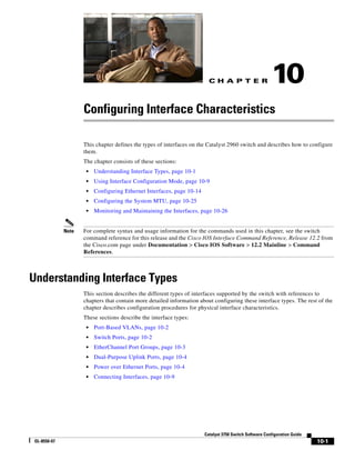
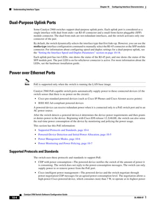
![10-8
Catalyst 3750 Switch Software Configuration Guide
OL-8550-07
Chapter 10 Configuring Interface Characteristics
Understanding Interface Types
Use the first or second method in the previous list to manually configure the cutoff-power value by
entering the power inline consumption default wattage or the power inline [auto | static max]
max-wattage command. If you are not manually configuring the cutoff-power value, the switch
automatically determines the value by using CDP power negotiation or the device IEEE classification,
which is the third method in the list. If the switch cannot determine the value by using one of these
methods, it uses the default value of 15.4 W, which is the fourth method in the list.
Power Consumption Values
You can configure the initial power allocation and the maximum power allocation on a port. However,
these values are only the configured values that determine when the switch should turn on or turn off
power on the PoE port. The maximum power allocation is not the same as the actual power consumption
of the powered device. The actual cutoff power value that the switch uses for power policing is not equal
to the configured power value.
When power policing is enabled, the switch polices the power usage at the switch port, which is greater
than the power consumption of the device. When you manually set the maximum power allocation, you
must consider the power loss over the cable from the switch port to the powered device. The cutoff power
is the sum of the rated power consumption of the powered device and the worst-case power loss over the
cable.
The actual amount of power consumed by a powered device on a PoE port is the cutoff-power value plus
a calibration factor of 500 mW (0.5 W). The actual cutoff value is approximate and varies from the
configured value by a percentage of the configured value. For example, if the configured cutoff power is
12 W, the actual cutoff-value is 11.4 W, which is 0.05% less than the configured value.
We recommend that you enable power policing when PoE is enabled on your switch. For example, if
policing is disabled and you set the cutoff-power value by using the power inline auto max 6300
interface configuration command, the configured maximum power allocation on the PoE port is 6.3 W
(6300 mW). The switch provides power to the connected devices on the port if the device needs up to
6.3 W. If the CDP-power negotiated value or the IEEE classification value exceeds the configured cutoff
value, the switch does not provide power to the connected device. After the switch turns on power to the
PoE port, the switch does not police the real-time power consumption of the device, and the device can
consume more power than the maximum allocated amount, which could adversely affect the switch and
the devices connected to the other PoE ports.
Because the switch supports internal power supplies and the Cisco Redundant Power System 2300 (also
referred to as the RPS 2300), the total amount of power available for the powered devices varies
depending on the power supply configuration.
• If a power supply is removed and replaced by a new power supply with less power and the switch
does not have enough power for the powered devices, the switch denies power to the PoE ports that
are in auto mode in descending order of the port numbers. If the switch still does not have enough
power, it denies power to the PoE ports in static mode in descending order of the port numbers.
• If the new power supply supports more power than the previous one and the switch now has more
power available, the switch grants power to the PoE ports in static mode in ascending order of the
port numbers. If it still has power available, the switch then grants power to the PoE ports in auto
mode in ascending order of the port numbers.](https://image.slidesharecdn.com/2960scg-150701081942-lva1-app6891/85/Cisco-2960-Switch-Configuration-276-320.jpg)
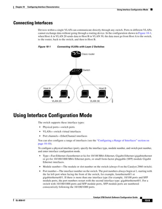
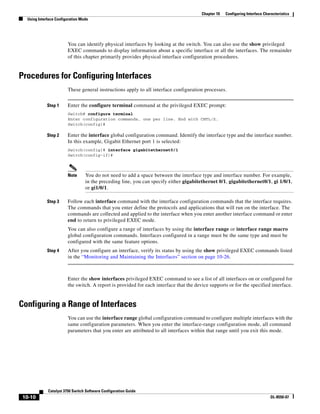
![10-11
Catalyst 3750 Switch Software Configuration Guide
OL-8550-07
Chapter 10 Configuring Interface Characteristics
Using Interface Configuration Mode
Beginning in privileged EXEC mode, follow these steps to configure a range of interfaces with the
same parameters:
When using the interface range global configuration command, note these guidelines:
• Valid entries for port-range:
– vlan vlan-ID, where the VLAN ID is 1 to 4094
Note Although the command-line interface shows options to set multiple VLANs, these
options are not supported.
– fastethernet stack member/module/{first port} - {last port}, where the module is always 0
– gigabitethernet module/{first port} - {last port}, where the module is always 0
– port-channel port-channel-number - port-channel-number, where the port-channel-number
is 1 to 6
Note When you use the interface range command with port channels, the first and last
port-channel number must be active port channels.
• You must add a space between the first interface number and the hyphen when using the
interface range command. For example, the command interface range gigabitethernet0/1 - 4 is a
valid range; the command interface range gigabitethernet0/1-4 is not a valid range.
• The interface range command only works with VLAN interfaces that have been configured with
the interface vlan command. The show running-config privileged EXEC command displays the
configured VLAN interfaces. VLAN interfaces not displayed by the show running-config
command cannot be used with the interface range command.
Command Purpose
Step 1 configure terminal Enter global configuration mode.
Step 2 interface range {port-range | macro
macro_name}
Specify the range of interfaces (VLANs or physical ports) to be
configured, and enter interface-range configuration mode.
• You can use the interface range command to configure up to five
port ranges or a previously defined macro.
• The macro variable is explained in the “Configuring and Using
Interface Range Macros” section on page 10-12.
• In a comma-separated port-range, you must enter the interface
type for each entry and enter spaces before and after the comma.
• In a hyphen-separated port-range, you do not need to re-enter the
interface type, but you must enter a space before the hyphen.
Step 3 Use the normal configuration commands to apply the configuration
parameters to all interfaces in the range. Each command is executed
as it is entered.
Step 4 end Return to privileged EXEC mode.
Step 5 show interfaces [interface-id] Verify the configuration of the interfaces in the range.
Step 6 copy running-config startup-config (Optional) Save your entries in the configuration file.](https://image.slidesharecdn.com/2960scg-150701081942-lva1-app6891/85/Cisco-2960-Switch-Configuration-279-320.jpg)
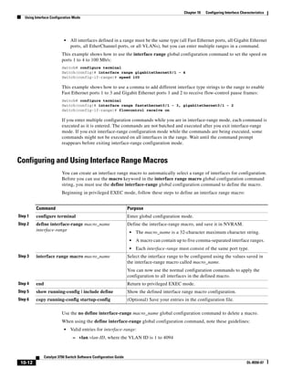
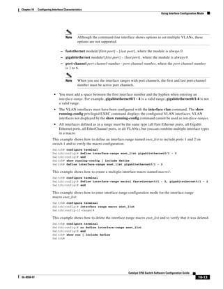
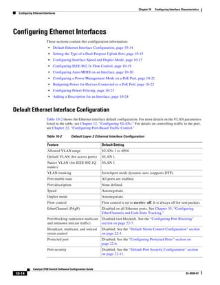
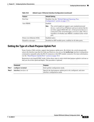
![10-18
Catalyst 3750 Switch Software Configuration Guide
OL-8550-07
Chapter 10 Configuring Interface Characteristics
Configuring Ethernet Interfaces
Setting the Interface Speed and Duplex Parameters
Beginning in privileged EXEC mode, follow these steps to set the speed and duplex mode for a physical
interface:
Use the no speed and no duplex interface configuration commands to return the interface to the default
speed and duplex settings (autonegotiate). To return all interface settings to the defaults, use the default
interface interface-id interface configuration command.
This example shows how to set the interface speed to 10 Mb/s and the duplex mode to half on a
10/100 Mb/s port:
Switch# configure terminal
Switch(config)# interface fasttethernet0/3
Switch(config-if)# speed 10
Switch(config-if)# duplex half
This example shows how to set the interface speed to 100 Mb/s on a 10/100/1000 Mb/s port:
Switch# configure terminal
Switch(config)# interface gigabitethernet0/2
Switch(config-if)# speed 100
Command Purpose
Step 1 configure terminal Enter global configuration mode.
Step 2 interface interface-id Specify the physical interface to be configured, and enter interface
configuration mode.
Step 3 speed {10 | 100 | 1000 | auto [10 | 100 |
1000] | nonegotiate}
Enter the appropriate speed parameter for the interface:
• Enter 10, 100, or 1000 to set a specific speed for the interface.
The 1000 keyword is available only for 10/100/1000 Mb/s ports.
• Enter auto to enable the interface to autonegotiate speed with the
connected device. If you use the 10, 100, or the 1000 keywords
with the auto keyword, the port autonegotiates only at the
specified speeds.
• The nonegotiate keyword is available only for SFP module ports.
SFP module ports operate only at 1000 Mb/s but can be
configured to not negotiate if connected to a device that does not
support autonegotiation.
For more information about speed settings, see the “Speed and Duplex
Configuration Guidelines” section on page 10-17.
Step 4 duplex {auto | full | half} Enter the duplex parameter for the interface.
Enable half-duplex mode (for interfaces operating only at 10 or
100 Mb/s). You cannot configure half-duplex mode for interfaces
operating at 1000 Mb/s.
For more information about duplex settings, see the “Speed and
Duplex Configuration Guidelines” section on page 10-17.
Step 5 end Return to privileged EXEC mode.
Step 6 show interfaces interface-id Display the interface speed and duplex mode configuration.
Step 7 copy running-config startup-config (Optional) Save your entries in the configuration file.](https://image.slidesharecdn.com/2960scg-150701081942-lva1-app6891/85/Cisco-2960-Switch-Configuration-286-320.jpg)
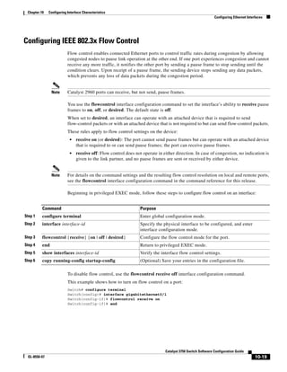
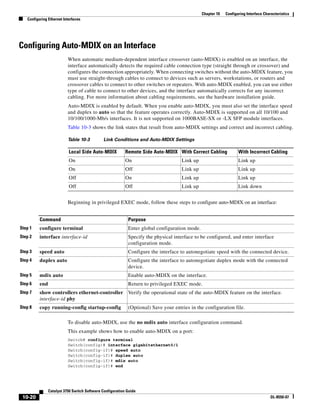
![10-21
Catalyst 3750 Switch Software Configuration Guide
OL-8550-07
Chapter 10 Configuring Interface Characteristics
Configuring Ethernet Interfaces
Configuring a Power Management Mode on a PoE Port
Note PoE commands are supported only when the switch is running the LAN base image.
For most situations, the default configuration (auto mode) works well, providing plug-and-play
operation. No further configuration is required. However, use the following procedure to give a PoE port
higher priority, to make it data only, or to specify a maximum wattage to disallow high-power powered
devices on a port.
Note When you make PoE configuration changes, the port being configured drops power. Depending on the
new configuration, the state of the other PoE ports, and the state of the power budget, the port might not
be powered up again. For example, port 1 is in the auto and on state, and you configure it for static mode.
The switch removes power from port 1, detects the powered device, and repowers the port. If port 1 is
in the auto and on state and you configure it with a maximum wattage of 10 W, the switch removes power
from the port and then redetects the powered device. The switch repowers the port only if the powered
device is a Class 1, Class 2, or a Cisco-only powered device.
Beginning in privileged EXEC mode, follow these steps to configure a power management mode on a
PoE-capable port:
Command Purpose
Step 1 configure terminal Enter global configuration mode.
Step 2 interface interface-id Specify the physical port to be configured, and enter interface
configuration mode.
Step 3 power inline {auto [max max-wattage] |
never | static [max max-wattage]}
Configure the PoE mode on the port. The keywords have these meanings:
• auto—Enable powered-device detection. If enough power is
available, automatically allocate power to the PoE port after device
detection. This is the default setting.
• (Optional) max max-wattage—Limit the power allowed on the port.
The range is 4000 to 15400 milliwatts. If no value is specified, the
maximum is allowed (15400 milliwatts).
• never—Disable device detection, and disable power to the port.
Note If a port has a Cisco powered device connected to it, do not use
the power inline never command to configure the port. A false
link-up can occur, placing the port into an error-disabled state.
• static—Enable powered-device detection. Pre-allocate (reserve)
power for a port before the switch discovers the powered device. The
switch reserves power for this port even when no device is connected
and guarantees that power will be provided upon device detection.
The switch allocates power to a port configured in static mode before it
allocates power to a port configured in auto mode.
Step 4 end Return to privileged EXEC mode.
Step 5 show power inline [interface-id] Display PoE status for a switch or for the specified interface.
Step 6 copy running-config startup-config (Optional) Save your entries in the configuration file.](https://image.slidesharecdn.com/2960scg-150701081942-lva1-app6891/85/Cisco-2960-Switch-Configuration-289-320.jpg)
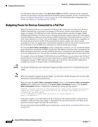
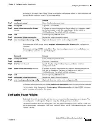
![10-24
Catalyst 3750 Switch Software Configuration Guide
OL-8550-07
Chapter 10 Configuring Interface Characteristics
Configuring Ethernet Interfaces
Beginning in privileged EXEC mode, follow these steps to enable policing of the real-time power
consumption of a powered device connected to a PoE port:
To disable policing of the real-time power consumption, use the no power inline police interface
configuration command. To disable error recovery for PoE error-disabled cause, use the no errdisable
recovery cause inline-power global configuration command.
For information about the output from the show power inline police privileged EXEC command, see
the command reference for this release.
Adding a Description for an Interface
You can add a description about an interface to help you remember its function. The description appears
in the output of these privileged EXEC commands: show configuration, show running-config, and
show interfaces.
Command Purpose
Step 1 configure terminal Enter global configuration mode.
Step 2 interface interface-id Specify the physical port to be configured, and enter interface
configuration mode.
Step 3 power inline police [action log] If the real-time power consumption exceeds the maximum power
allocation on the port, configure the switch to take one of these actions:
• Shut down the PoE port, turn off power to it, and put it in the
error-dsabled state—Enter the power inline police command.
Note You can enable error detection for the PoE error-disabled cause
by using the errdisable detect cause inline-power global
configuration command. You can also enable the timer to recover
from the PoE error-disabled state by using the errdisable
recovery cause inline-power interval interval global
configuration command.
• Generate a syslog message while still providing power to the
port—Enter the power inline police action log command.
If you do not enter the action log keywords, the default action shuts down
the port and puts the port in the error-disabled state.
Step 4 exit Return to global configuration mode.
Step 5 errdisable detect cause inline-power
and
errdisable recovery cause inline-power
and
errdisable recovery interval interval
(Optional) Enable error recovery from the PoE error-disabled state, and
configure the PoE recover mechanism variables.
For interval interval, specify the time in seconds to recover from the
error-disabled state. The range is 30 to 86400.
By default, the recovery interval is 300 seconds.
Step 6 exit Return to privileged EXEC mode.
Step 7 show power inline police
show errdisable recovery
Display the power monitoring status, and verify the error recovery
settings.
Step 8 copy running-config startup-config (Optional) Save your entries in the configuration file.](https://image.slidesharecdn.com/2960scg-150701081942-lva1-app6891/85/Cisco-2960-Switch-Configuration-292-320.jpg)
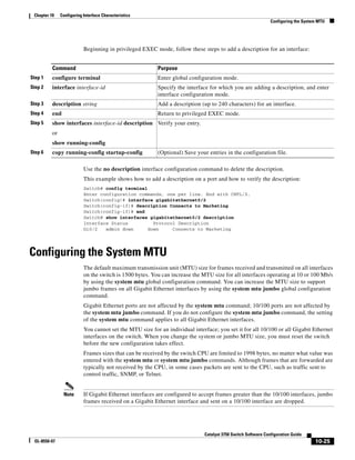
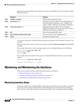
![10-27
Catalyst 3750 Switch Software Configuration Guide
OL-8550-07
Chapter 10 Configuring Interface Characteristics
Monitoring and Maintaining the Interfaces
commands by using the show ? command at the privileged EXEC prompt.) These commands are fully
described in the Cisco IOS Interface Command Reference, Release 12.2 from the Cisco.com page under
Documentation > Cisco IOS Software > 12.2 Mainline > Command References.
Clearing and Resetting Interfaces and Counters
Table 10-5 lists the privileged EXEC mode clear commands that you can use to clear counters and reset
interfaces.
Table 10-4 Show Commands for Interfaces
Command Purpose
show interfaces [interface-id] (Optional) Display the status and configuration of all interfaces or a
specific interface.
show interfaces interface-id status [err-disabled] (Optional) Display interface status or a list of interfaces in an
error-disabled state.
show interfaces [interface-id] switchport (Optional) Display administrative and operational status of switching
ports.
show interfaces [interface-id] description (Optional) Display the description configured on an interface or all
interfaces and the interface status.
show ip interface [interface-id] (Optional) Display the usability status of all interfaces configured for
IP routing or the specified interface.
show interface [interface-id] stats (Optional) Display the input and output packets by the switching path
for the interface.
show interfaces transceiver properties (Optional) Display speed and duplex settings on the interface.
show interfaces [interface-id] [{transceiver
properties | detail}] module number]
Display physical and operational status about an SFP module.
show running-config interface [interface-id] Display the running configuration in RAM for the interface.
show version Display the hardware configuration, software version, the names and
sources of configuration files, and the boot images.
show controllers ethernet-controller interface-id
phy
Display the operational state of the auto-MDIX feature on the
interface.
show power inline [interface-id] Display PoE status for a switch or for an interface.
show power inline police Display the power policing data.
Table 10-5 Clear Commands for Interfaces
Command Purpose
clear counters [interface-id] Clear interface counters.
clear interface interface-id Reset the hardware logic on an interface.
clear line [number | console 0 | vty number] Reset the hardware logic on an asynchronous serial line.](https://image.slidesharecdn.com/2960scg-150701081942-lva1-app6891/85/Cisco-2960-Switch-Configuration-295-320.jpg)
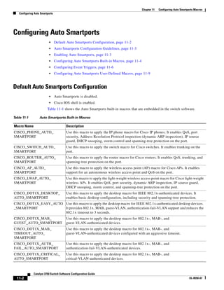
![11-3
Catalyst 3750 Switch Software Configuration Guide
OL-8550-07
Chapter 11 Configuring Auto Smartports Macros
Configuring Auto Smartports
Auto Smartports Configuration Guidelines
• The built-in macros cannot be deleted or changed. However, you can override a built-in macro by
creating a user-defined macro with the same name. To restore the original built-in macro, delete the
user-defined macro.
• To avoid system conflicts when Auto Smartports macros are applied, remove all port configuration
except for 802.1x authentication.
• If the macro conflicts with the original configuration, some macro commands might not be applied,
or some antimacro commands might not be removed. (The antimacro is the portion of the applied
macro that removes it at link down.)
For example, if 802.1x authentication is enabled, you cannot remove switchport-mode access
configuration. Remove the 802.1x authentication before removing the switchport mode
configuration.
• A port should not be a member of an EtherChannel when applying Auto Smartports macros.
• The built-in macro default data VLAN is VLAN 1. The default voice VLAN is VLAN 2. You should
modify the built-in macro default values if your switch uses different VLANs. To view all built-in
macro default values, use the show shell functions privileged EXEC command.
• For 802.1x authentication or MAB, configure the RADIUS server to support the Cisco
attribute-value (av) pair auto-smart-port=event trigger to detect non-Cisco devices.
• For stationary devices that do not support CDP, MAB, or 802.1x authentication, such as network
printers, we recommend that you disable Auto Smartports on the port.
• If authentication is enabled on a port, the switch ignores CDP unless the cdp-fallback keyword is
in the macro auto global processing global configuration command.
• The order of CLI commands within the macro and the corresponding antimacro can be different.
Enabling Auto Smartports
To configure the switch to automatically apply Auto Smartports macros on all ports, use the macro auto
global processing global configuration command. To disable Auto Smartports macros on a specific port,
use the no auto global processing in the interface mode.
Beginning in privileged EXEC mode, follow these steps.
To return to the default setting, use the no macro auto global processing global configuration
command.
Command Purpose
Step 1 configure terminal Enter global configuration mode.
Step 2 macro auto global processing
[cdp-fallback]
Globally enable Auto Smartports on the switch.
(Optional) Use the cdp-fallback keyword to enable the switch to use
CDP capability information when a port is 802.1x-enabled and the
RADIUS server does not send an event trigger.
Step 3 end Return to privileged EXEC mode.
Step 4 show running-config Verify that Auto Smartports is enabled.
Step 5 copy running-config startup-config (Optional) Save your entries in the configuration file.](https://image.slidesharecdn.com/2960scg-150701081942-lva1-app6891/85/Cisco-2960-Switch-Configuration-299-320.jpg)
![11-5
Catalyst 3750 Switch Software Configuration Guide
OL-8550-07
Chapter 11 Configuring Auto Smartports Macros
Configuring Auto Smartports
Step 2 macro auto execute event trigger
builtin built-in macro name
[parameter=value] [parameter=value]
Define mapping from an event trigger to a built-in macro.
Specify an event trigger:
• CISCO_PHONE_EVENT
• CISCO_SWITCH_EVENT
• CISCO_ROUTER_EVENT
• CISCO_WIRELESS_AP_EVENT
• CISCO_WIRELESS_LIGHTWEIGHT_AP_EVENT
• WORD—Apply a user-defined event trigger.
Specify a builtin built-in macro name:
• CISCO_PHONE_AUTO_SMARTPORT
(Optional) Specify the parameter values: $ACCESS_VLAN=(1) and
$VOICE_VLAN=(2).
• CISCO_SWITCH_AUTO_SMARTPORT
(Optional) Specify the parameter values: $NATIVE_VLAN=(1).
• CISCO_ROUTER_AUTO_SMARTPORT
(Optional) Specify the parameter values: $NATIVE_VLAN=(1).
• CISCO_AP_AUTO_SMARTPORT
(Optional) Specify the parameter values: $NATIVE_VLAN=(1).
• CISCO_LWAP_AUTO_SMARTPORT
(Optional) Specify the parameter values: $ACCESS_VLAN=(1).
• CISCO_DOT1X_DESKTOP_AUTO_SMARTPORT
(Optional) Specify the parameter values: $ACCESS_VLAN=(1).
• CISCO_DOT1X_EASY_AUTO_SMARTPORT
(Optional) Specify the parameter values: $ACCESS_VLAN=(1).
• CISCO_DOT1X_MAB_GUEST_AUTO_SMARTPORT
(Optional) Specify the parameter values: $ACCESS_VLAN=(1).
• CISCO_DOT1X_MAB_TIMEOUT_AUTO_SMARTPORT
(Optional) Specify the parameter values: $ACCESS_VLAN=(1).
• CISCO_DOT1X_AUTH_FAIL_AUTO_SMARTPORT
(Optional) Specify the parameter values: $ACCESS_VLAN=(1).
• CISCO_DOT1X_CRITICAL_AUTO_SMARTPORT
(Optional) Specify the parameter values: $CRITICAL_VLAN=(1).
(Optional) parameter=value—Replace default values that begin with $.
Enter new values in the form of name value pair separated by a space:
[<name1>=<value1> <name2>=<value2>...]. Default values are shown in
parenthesis.
Step 3 end Return to privileged EXEC mode.
Step 4 show running-config Verify your entries.
Step 5 copy running-config startup-config (Optional) Save your entries in the configuration file.
Command Purpose](https://image.slidesharecdn.com/2960scg-150701081942-lva1-app6891/85/Cisco-2960-Switch-Configuration-301-320.jpg)
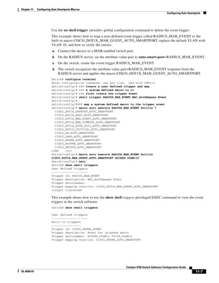
![11-8
Catalyst 3750 Switch Software Configuration Guide
OL-8550-07
Chapter 11 Configuring Auto Smartports Macros
Configuring Auto Smartports
Trigger Id: CISCO_ROUTER_EVENT
Trigger description: Event for router macro
Trigger environment: NATIVE_VLAN=1
Trigger mapping function: CISCO_ROUTER_AUTO_SMARTPORT
Trigger Id: CISCO_SWITCH_EVENT
Trigger description: Event for switch macro
Trigger environment: NATIVE_VLAN=1
Trigger mapping function: CISCO_SWITCH_AUTO_SMARTPORT
Trigger Id: CISCO_WIRELESS_AP_EVENT
Trigger description: Event for Wireless Access Point macro
Trigger environment: NATIVE_VLAN=1
Trigger mapping function: CISCO_AP_AUTO_SMARTPORT
Trigger Id: CISCO_WIRELESS_LIGHTWEIGHT_AP_EVENT
Trigger description: Event for Wireless Lightweight Access Point macro
Trigger environment: NATIVE_VLAN=1
Trigger mapping function: CISCO_LWAP_AUTO_SMARTPORT
This example shows how to use the show shell functions privileged EXEC command to view the built-in
macros in the switch software:
Switch# show shell functions
#User defined functions:
#Built-in functions:
function CISCO_AP_AUTO_SMARTPORT () {
if [[ $LINKUP -eq YES ]]; then
conf t
interface $INTERFACE
macro description $TRIGGER
switchport trunk encapsulation dot1q
switchport trunk native vlan $NATIVE_VLAN
switchport trunk allowed vlan ALL
switchport mode trunk
switchport nonegotiate
auto qos voip trust
mls qos trust cos
exit
end
fi
if [[ $LINKUP -eq NO ]]; then
conf t
interface $INTERFACE
no macro description
no switchport nonegotiate
no switchport trunk native vlan $NATIVE_VLAN
no switchport trunk allowed vlan ALL
no auto qos voip trust
no mls qos trust cos
if [[ $AUTH_ENABLED -eq NO ]]; then
no switchport mode
no switchport trunk encapsulation
fi
exit
end
fi
}](https://image.slidesharecdn.com/2960scg-150701081942-lva1-app6891/85/Cisco-2960-Switch-Configuration-304-320.jpg)
![11-9
Catalyst 3750 Switch Software Configuration Guide
OL-8550-07
Chapter 11 Configuring Auto Smartports Macros
Configuring Auto Smartports
function CISCO_SWITCH_AUTO_SMARTPORT () {
if [[ $LINKUP -eq YES ]]; then
conf t
interface $INTERFACE
macro description $TRIGGER
auto qos voip trust
switchport trunk encapsulation dot1q
switchport trunk native vlan $NATIVE_VLAN
switchport trunk allowed vlan ALL
switchport mode trunk
exit
end
else
conf t
interface $INTERFACE
no macro description
no auto qos voip trust
no switchport mode trunk
no switchport trunk encapsulation dot1q
no switchport trunk native vlan $NATIVE_VLAN
no switchport trunk allowed vlan ALL
exit
end
fi
}
<output truncated>
Configuring Auto Smartports User-Defined Macros
The Cisco IOS shell provides basic scripting capabilities for configuring the user-defined Auto
Smartports macros. These macros can contain multiple lines and can include any CLI command. You
can also define variable substitution, conditionals, functions, and triggers within the macro.
Beginning in privileged EXEC mode, follow these steps to map a user-defined event trigger to a
user-defined macro.
Command Purpose
Step 1 configure terminal Enter global configuration mode.
Step 2 macro auto execute event trigger
[parameter=value] { function
contents }
Specify a user-defined macro that maps to an event trigger.
{ function contents } Specify a user-defined macro to associate with the
trigger. Enter the macro contents within braces. Begin the IOS shell
commands with the left brace and end the command grouping with the right
brace.
(Optional) parameter=value—Replace default values that begin with $, enter
new values in the form of name value pair separated by a space:
[<name1>=<value1> <name2>=<value2>...].
Step 3 end Return to privileged EXEC mode.
Step 4 show running-config Verify your entries.
Step 5 copy running-config startup-config (Optional) Save your entries in the configuration file.](https://image.slidesharecdn.com/2960scg-150701081942-lva1-app6891/85/Cisco-2960-Switch-Configuration-305-320.jpg)
![11-10
Catalyst 3750 Switch Software Configuration Guide
OL-8550-07
Chapter 11 Configuring Auto Smartports Macros
Configuring Auto Smartports
This example shows how to map a user-defined event trigger called Cisco Digital Media Player (DMP)
to a user-defined macro.
a. Connect the DMP to an 802.1x- or MAB-enabled switch port.
b. On the RADIUS server, set the attribute-value pair to auto-smart-port =CISCO_DMP_EVENT.
c. On the switch, create the event trigger CISCO_DMP_EVENT, and enter the user-defined macro
commands shown below.
d. The switch recognizes the attribute-value pair=CISCO_DMP_EVENT response from the RADIUS
server and applies the macro associated with this event trigger.
Switch(config)# shell trigger CISCO_DMP_EVENT Cisco DMP player
Switch(config)# macro auto execute CISCO_DMP_EVENT {
if [[ $LINKUP -eq YES ]]; then
conf t
interface $INTERFACE
macro description $TRIGGER
switchport access vlan 1
switchport mode access
switchport port-security
switchport port-security maximum 1
switchport port-security violation restrict
switchport port-security aging time 2
switchport port-security aging type inactivity
spanning-tree portfast
spanning-tree bpduguard enable
exit
fi
if [[ $LINKUP -eq NO ]]; then
conf t
interface $INTERFACE
no macro description $TRIGGER
no switchport access vlan 1
if [[ $AUTH_ENABLED -eq NO ]]; then
no switchport mode access
fi
no switchport port-security
no switchport port-security maximum 1
no switchport port-security violation restrict
no switchport port-security aging time 2
no switchport port-security aging type inactivity
no spanning-tree portfast
no spanning-tree bpduguard enable
exit
fi
}
Switch(config)# end
Table 11-2 Supported Cisco IOS Shell Keywords
Command Description
{ Begin the command grouping.
} End the command grouping.
[[ Use as a conditional construct.
]] Use as a conditional construct.
else Use as a conditional construct.
-eq Use as a conditional construct.](https://image.slidesharecdn.com/2960scg-150701081942-lva1-app6891/85/Cisco-2960-Switch-Configuration-306-320.jpg)
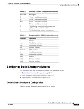
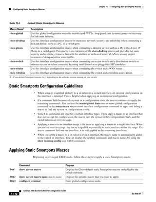
![11-13
Catalyst 3750 Switch Software Configuration Guide
OL-8550-07
Chapter 11 Configuring Auto Smartports Macros
Configuring Static Smartports Macros
You can only delete a global macro-applied configuration on a switch by entering the no version of each
command in the macro. You can delete a macro-applied configuration on a port by entering the default
interface interface-id interface configuration command.
This example shows how to display the cisco-desktop macro, to apply the macro and to set the access
VLAN ID to 25 on an interface:
Switch# show parser macro cisco-desktop
--------------------------------------------------------------
Macro name : cisco-desktop
Step 4 macro global {apply | trace}
macro-name [parameter {value}]
[parameter {value}] [parameter
{value}]
Apply each individual command defined in the macro to the switch by
entering macro global apply macro-name. Specify macro global trace
macro-name to apply and to debug a macro to find any syntax or
configuration errors.
Append the macro with the required values by using the parameter
value keywords. Keywords that begin with $ require a unique parameter
value.
You can use the macro global apply macro-name ? command to display
a list of any required values for the macro. If you apply a macro without
entering the keyword values, the commands are invalid and are not
applied.
(Optional) Specify unique parameter values that are specific to the
switch. You can enter up to three keyword-value pairs. Parameter
keyword matching is case sensitive. The corresponding value replaces
all matching occurrences of the keyword.
Step 5 interface interface-id (Optional) Enter interface configuration mode, and specify the interface
on which to apply the macro.
Step 6 default interface interface-id (Optional) Clear all configuration from the specified interface.
Step 7 macro {apply | trace} macro-name
[parameter {value}] [parameter
{value}] [parameter {value}]
Apply each individual command defined in the macro to the port by
entering macro global apply macro-name. Specify macro global trace
macro-name to apply and to debug a macro to find any syntax or
configuration errors.
Append the macro with the required values by using the parameter
value keywords. Keywords that begin with $ require a unique parameter
value.
You can use the macro global apply macro-name ? command to display
a list of any required values for the macro. If you apply a macro without
entering the keyword values, the commands are invalid and are not
applied.
(Optional) Specify unique parameter values that are specific to the
switch. You can enter up to three keyword-value pairs. Parameter
keyword matching is case sensitive. The corresponding value replaces
all matching occurrences of the keyword.
Step 8 end Return to privileged EXEC mode.
Step 9 show running-config interface
interface-id
Verify that the macro is applied to an interface.
Step 10 copy running-config startup-config (Optional) Save your entries in the configuration file.
Command Purpose](https://image.slidesharecdn.com/2960scg-150701081942-lva1-app6891/85/Cisco-2960-Switch-Configuration-309-320.jpg)
![11-14
Catalyst 3750 Switch Software Configuration Guide
OL-8550-07
Chapter 11 Configuring Auto Smartports Macros
Displaying Auto Smartports and Static Smartports Macros
Macro type : default
# Basic interface - Enable data VLAN only
# Recommended value for access vlan (AVID) should not be 1
switchport access vlan $AVID
switchport mode access
# Enable port security limiting port to a single
# MAC address -- that of desktop
switchport port-security
switchport port-security maximum 1
# Ensure port-security age is greater than one minute
# and use inactivity timer
switchport port-security violation restrict
switchport port-security aging time 2
switchport port-security aging type inactivity
# Configure port as an edge network port
spanning-tree portfast
spanning-tree bpduguard enable
--------------------------------------------------------------
Switch#
Switch# configure terminal
Switch(config)# interface gigabitethernet0/4
Switch(config-if)# macro apply cisco-desktop $AVID 25
Displaying Auto Smartports and Static Smartports Macros
To display the Auto Smartports and static Smartports macros, use one or more of the privileged EXEC
commands in Table 11-5.
Table 11-5 Commands for Displaying Auto Smartports and Static Smartports Macros
Command Purpose
show parser macro Displays all static Smartports macros.
show parser macro name macro-name Displays a specific static Smartports macro.
show parser macro brief Displays the static Smartports macro names.
show parser macro description [interface
interface-id]
Displays the static Smartports macro description for all interfaces or
for a specified interface.
show shell Displays information about Auto Smartports event triggers and
macros.](https://image.slidesharecdn.com/2960scg-150701081942-lva1-app6891/85/Cisco-2960-Switch-Configuration-310-320.jpg)
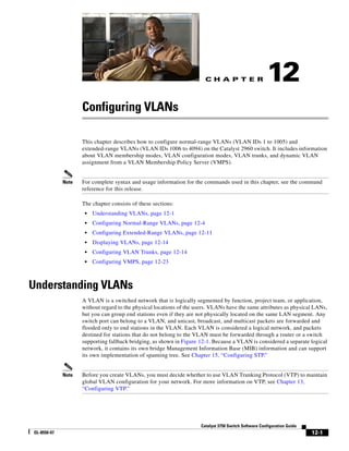
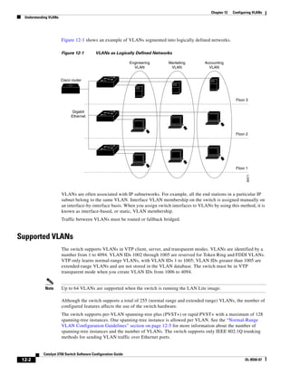
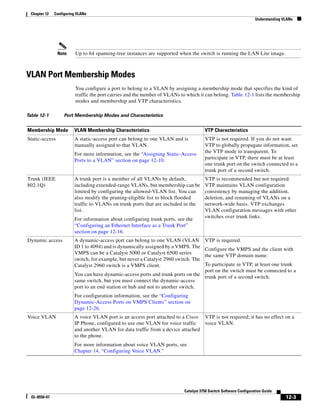
![12-4
Catalyst 3750 Switch Software Configuration Guide
OL-8550-07
Chapter 12 Configuring VLANs
Configuring Normal-Range VLANs
For more detailed definitions of access and trunk modes and their functions, see Table 12-4 on
page 12-15.
When a port belongs to a VLAN, the switch learns and manages the addresses associated with the port
on a per-VLAN basis. For more information, see the “Managing the MAC Address Table” section on
page 6-19.
Configuring Normal-Range VLANs
Normal-range VLANs are VLANs with VLAN IDs 1 to 1005. If the switch is in VTP server or
VTP transparent mode, you can add, modify or remove configurations for VLANs 2 to 1001 in the
VLAN database. (VLAN IDs 1 and 1002 to 1005 are automatically created and cannot be removed.)
Note When the switch is in VTP transparent mode, you can also create extended-range VLANs (VLANs with
IDs from 1006 to 4094), but these VLANs are not saved in the VLAN database. See the “Configuring
Extended-Range VLANs” section on page 12-11.
Configurations for VLAN IDs 1 to 1005 are written to the file vlan.dat (VLAN database), and you can
display them by entering the show vlan privileged EXEC command. The vlan.dat file is stored in flash
memory.
Caution You can cause inconsistency in the VLAN database if you attempt to manually delete the vlan.dat file.
If you want to modify the VLAN configuration, use the commands described in these sections and in the
command reference for this release. To change the VTP configuration, see Chapter 13, “Configuring
VTP.”
You use the interface configuration mode to define the port membership mode and to add and remove
ports from VLANs. The results of these commands are written to the running-configuration file, and you
can display the file by entering the show running-config privileged EXEC command.
You can set these parameters when you create a new normal-range VLAN or modify an existing VLAN
in the VLAN database:
• VLAN ID
• VLAN name
• VLAN type (Ethernet, Fiber Distributed Data Interface [FDDI], FDDI network entity title [NET],
TrBRF, or TrCRF, Token Ring, Token Ring-Net)
• VLAN state (active or suspended)
• Maximum transmission unit (MTU) for the VLAN
• Security Association Identifier (SAID)
• Bridge identification number for TrBRF VLANs
• Ring number for FDDI and TrCRF VLANs
• Parent VLAN number for TrCRF VLANs
• Spanning Tree Protocol (STP) type for TrCRF VLANs
• VLAN number to use when translating from one VLAN type to another](https://image.slidesharecdn.com/2960scg-150701081942-lva1-app6891/85/Cisco-2960-Switch-Configuration-314-320.jpg)
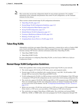
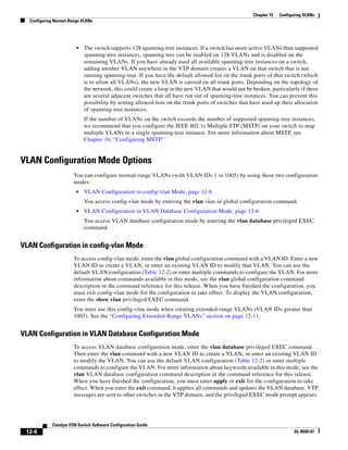
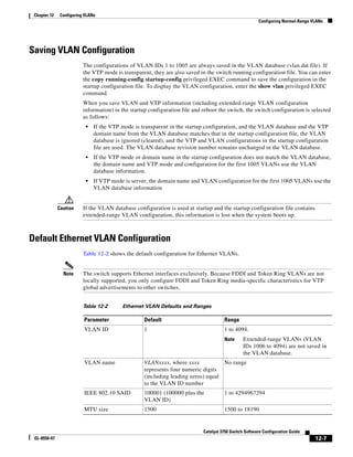
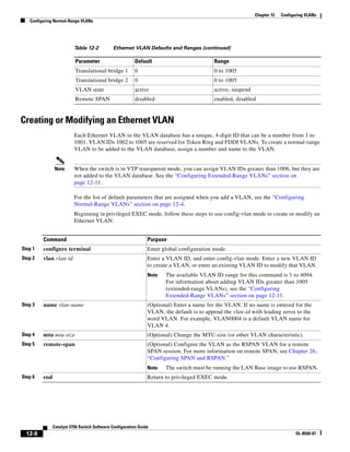
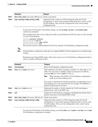
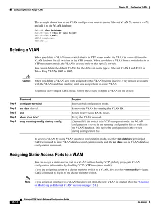
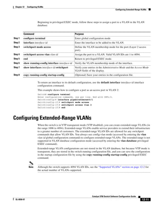
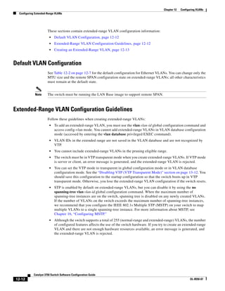
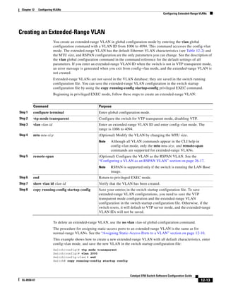
![12-14
Catalyst 3750 Switch Software Configuration Guide
OL-8550-07
Chapter 12 Configuring VLANs
Displaying VLANs
Displaying VLANs
Use the show vlan privileged EXEC command to display a list of all VLANs on the switch, including
extended-range VLANs. The display includes VLAN status, ports, and configuration information. To
view normal-range VLANs in the VLAN database (1 to 1005), use the show VLAN database
configuration command (accessed by entering the vlan database privileged EXEC command).
Table 12-3 lists the commands for monitoring VLANs.
For more details about the show command options and explanations of output fields, see the command
reference for this release.
Configuring VLAN Trunks
These sections contain this conceptual information:
• Trunking Overview, page 12-14
• Default Layer 2 Ethernet Interface VLAN Configuration, page 12-16
• Configuring an Ethernet Interface as a Trunk Port, page 12-16
• Configuring Trunk Ports for Load Sharing, page 12-20
Trunking Overview
A trunk is a point-to-point link between one or more Ethernet switch interfaces and another networking device
such as a router or a switch. Ethernet trunks carry the traffic of multiple VLANs over a single link, and you
can extend the VLANs across an entire network. The switch supports IEEE 802.1Q encapsulation.
You can configure a trunk on a single Ethernet interface or on an EtherChannel bundle. For more
information about EtherChannel, see Chapter 35, “Configuring EtherChannels and Link-State
Tracking.”
Ethernet trunk interfaces support different trunking modes (see Table 12-4). You can set an interface as
trunking or nontrunking or to negotiate trunking with the neighboring interface. To autonegotiate
trunking, the interfaces must be in the same VTP domain.
Trunk negotiation is managed by the Dynamic Trunking Protocol (DTP), which is a Point-to-Point
Protocol. However, some internetworking devices might forward DTP frames improperly, which could
cause misconfigurations.
Table 12-3 VLAN Monitoring Commands
Command Command Mode Purpose
show VLAN database configuration Display status of VLANs in the VLAN database.
show current [vlan-id] VLAN database configuration Display status of all or the specified VLAN in the VLAN
database.
show interfaces [vlan
vlan-id]
Privileged EXEC Display characteristics for all interfaces or for the specified
VLAN configured on the switch.
show vlan [id vlan-id] Privileged EXEC Display parameters for all VLANs or the specified VLAN on
the switch.](https://image.slidesharecdn.com/2960scg-150701081942-lva1-app6891/85/Cisco-2960-Switch-Configuration-324-320.jpg)
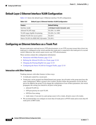
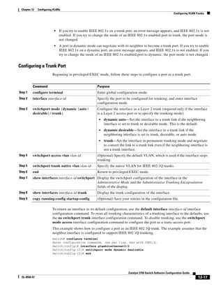
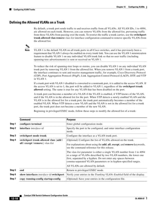
![12-19
Catalyst 3750 Switch Software Configuration Guide
OL-8550-07
Chapter 12 Configuring VLANs
Configuring VLAN Trunks
To return to the default allowed VLAN list of all VLANs, use the no switchport trunk allowed vlan
interface configuration command.
This example shows how to remove VLAN 2 from the allowed VLAN list on a port:
Switch(config)# interface gigabitethernet0/1
Switch(config-if)# switchport trunk allowed vlan remove 2
Switch(config-if)# end
Changing the Pruning-Eligible List
The pruning-eligible list applies only to trunk ports. Each trunk port has its own eligibility list. VTP
pruning must be enabled for this procedure to take effect. The “Enabling VTP Pruning” section on
page 13-14 describes how to enable VTP pruning.
Beginning in privileged EXEC mode, follow these steps to remove VLANs from the pruning-eligible list
on a trunk port:
To return to the default pruning-eligible list of all VLANs, use the no switchport trunk pruning vlan
interface configuration command.
Configuring the Native VLAN for Untagged Traffic
A trunk port configured with IEEE 802.1Q tagging can receive both tagged and untagged traffic. By
default, the switch forwards untagged traffic in the native VLAN configured for the port. The native
VLAN is VLAN 1 by default.
Note The native VLAN can be assigned any VLAN ID.
Command Purpose
Step 1 configure terminal Enter global configuration mode.
Step 2 interface interface-id Select the trunk port for which VLANs should be pruned, and enter
interface configuration mode.
Step 3 switchport trunk pruning vlan {add |
except | none | remove} vlan-list
[,vlan[,vlan[,,,]]
Configure the list of VLANs allowed to be pruned from the trunk. (See
the “VTP Pruning” section on page 13-4).
For explanations about using the add, except, none, and remove
keywords, see the command reference for this release.
Separate nonconsecutive VLAN IDs with a comma and no spaces; use a
hyphen to designate a range of IDs. Valid IDs are 2 to 1001.
Extended-range VLANs (VLAN IDs 1006 to 4094) cannot be pruned.
VLANs that are pruning-ineligible receive flooded traffic.
The default list of VLANs allowed to be pruned contains VLANs 2 to
1001.
Step 4 end Return to privileged EXEC mode.
Step 5 show interfaces interface-id switchport Verify your entries in the Pruning VLANs Enabled field of the display.
Step 6 copy running-config startup-config (Optional) Save your entries in the configuration file.](https://image.slidesharecdn.com/2960scg-150701081942-lva1-app6891/85/Cisco-2960-Switch-Configuration-329-320.jpg)
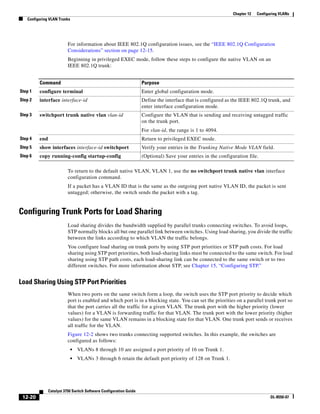
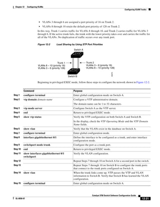
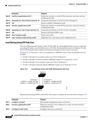
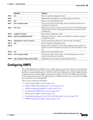
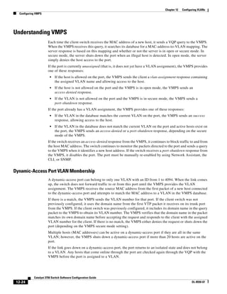
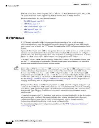
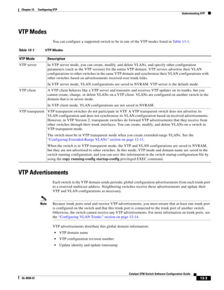
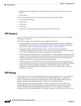
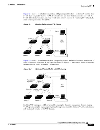
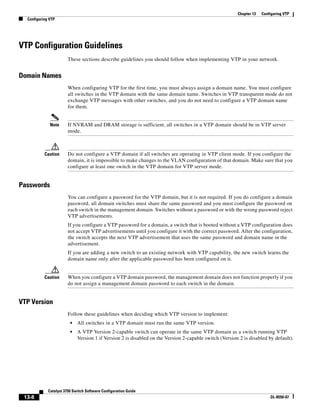
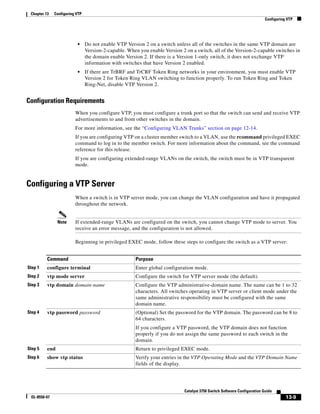
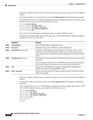
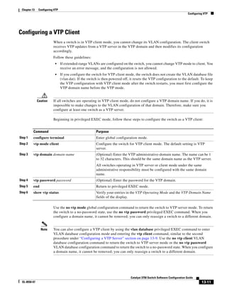
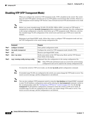
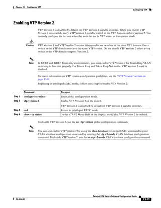
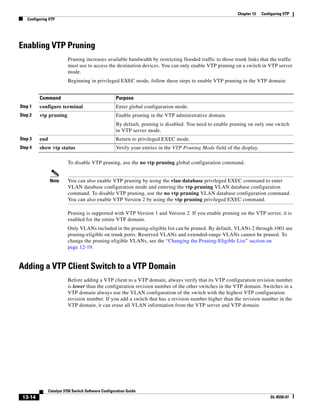
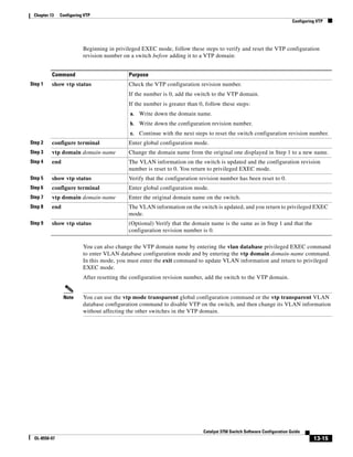
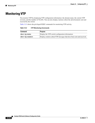
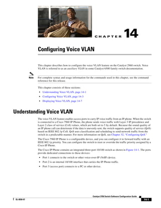
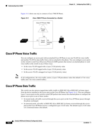
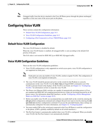
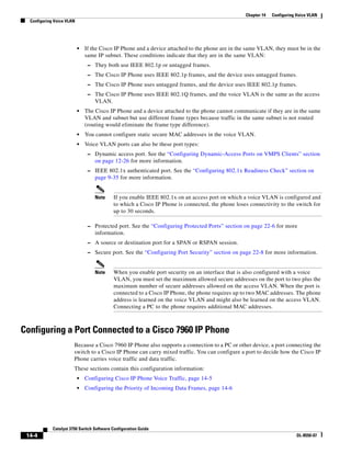
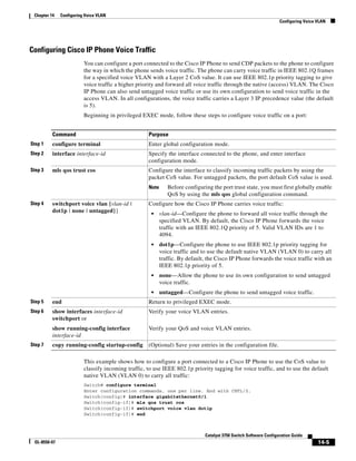


![15-2
Catalyst 3750 Switch Software Configuration Guide
OL-8550-07
Chapter 15 Configuring STP
Understanding Spanning-Tree Features
• Spanning-Tree Interoperability and Backward Compatibility, page 15-10
• STP and IEEE 802.1Q Trunks, page 15-10
For configuration information, see the “Configuring Spanning-Tree Features” section on page 15-10.
For information about optional spanning-tree features, see Chapter 17, “Configuring Optional
Spanning-Tree Features.”
STP Overview
STP is a Layer 2 link management protocol that provides path redundancy while preventing loops in the
network. For a Layer 2 Ethernet network to function properly, only one active path can exist between
any two stations. Multiple active paths among end stations cause loops in the network. If a loop exists
in the network, end stations might receive duplicate messages. Switches might also learn end-station
MAC addresses on multiple Layer 2 interfaces. These conditions result in an unstable network.
Spanning-tree operation is transparent to end stations, which cannot detect whether they are connected
to a single LAN segment or a switched LAN of multiple segments.
The STP uses a spanning-tree algorithm to select one switch of a redundantly connected network as the
root of the spanning tree. The algorithm calculates the best loop-free path through a switched Layer 2
network by assigning a role to each port based on the role of the port in the active topology:
• Root—A forwarding port elected for the spanning-tree topology
• Designated—A forwarding port elected for every switched LAN segment
• Alternate—A blocked port providing an alternate path to the root bridge in the spanning tree
• Backup—A blocked port in a loopback configuration
The switch that has all of its ports as the designated role or as the backup role is the root switch. The
switch that has at least one of its ports in the designated role is called the designated switch.
Spanning tree forces redundant data paths into a standby (blocked) state. If a network segment in the
spanning tree fails and a redundant path exists, the spanning-tree algorithm recalculates the
spanning-tree topology and activates the standby path. Switches send and receive spanning-tree frames,
called bridge protocol data units (BPDUs), at regular intervals. The switches do not forward these frames
but use them to construct a loop-free path. BPDUs contain information about the sending switch and its
ports, including switch and MAC addresses, switch priority, port priority, and path cost. Spanning tree
uses this information to elect the root switch and root port for the switched network and the root port and
designated port for each switched segment.
When two ports on a switch are part of a loop, the spanning-tree port priority and path cost settings
control which port is put in the forwarding state and which is put in the blocking state. The spanning-tree
port priority value represents the location of a port in the network topology and how well it is located to
pass traffic. The path cost value represents the media speed.
Note The default is for the switch to send keepalive messages (to ensure the connection is up) only on
interfaces that do not have small form-factor pluggable (SFP) modules. You can use the [no] keepalive
interface configuration command to change the default for an interface.](https://image.slidesharecdn.com/2960scg-150701081942-lva1-app6891/85/Cisco-2960-Switch-Configuration-366-320.jpg)
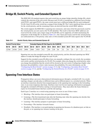
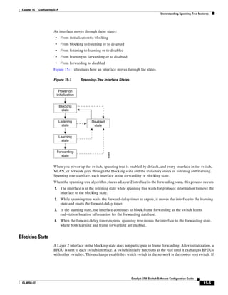
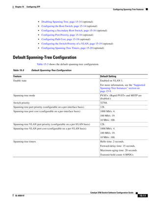
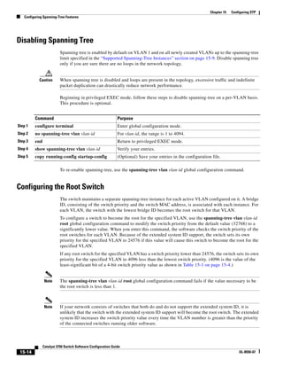
![15-15
Catalyst 3750 Switch Software Configuration Guide
OL-8550-07
Chapter 15 Configuring STP
Configuring Spanning-Tree Features
Note The root switch for each spanning-tree instance should be a backbone or distribution switch. Do not
configure an access switch as the spanning-tree primary root.
Use the diameter keyword to specify the Layer 2 network diameter (that is, the maximum number of
switch hops between any two end stations in the Layer 2 network). When you specify the network
diameter, the switch automatically sets an optimal hello time, forward-delay time, and maximum-age
time for a network of that diameter, which can significantly reduce the convergence time. You can use
the hello keyword to override the automatically calculated hello time.
Note After configuring the switch as the root switch, we recommend that you avoid manually configuring the
hello time, forward-delay time, and maximum-age time through the spanning-tree vlan vlan-id
hello-time, spanning-tree vlan vlan-id forward-time, and the spanning-tree vlan vlan-id max-age
global configuration commands.
Beginning in privileged EXEC mode, follow these steps to configure a switch to become the root for the
specified VLAN. This procedure is optional.
To return to the default setting, use the no spanning-tree vlan vlan-id root global configuration
command.
Command Purpose
Step 1 configure terminal Enter global configuration mode.
Step 2 spanning-tree vlan vlan-id root primary
[diameter net-diameter [hello-time seconds]]
Configure a switch to become the root for the specified VLAN.
• For vlan-id, you can specify a single VLAN identified by
VLAN ID number, a range of VLANs separated by a
hyphen, or a series of VLANs separated by a comma. The
range is 1 to 4094.
• (Optional) For diameter net-diameter, specify the
maximum number of switches between any two end
stations. The range is 2 to 7.
• (Optional) For hello-time seconds, specify the interval in
seconds between the generation of configuration messages
by the root switch. The range is 1 to 10; the default is 2.
Step 3 end Return to privileged EXEC mode.
Step 4 show spanning-tree detail Verify your entries.
Step 5 copy running-config startup-config (Optional) Save your entries in the configuration file.](https://image.slidesharecdn.com/2960scg-150701081942-lva1-app6891/85/Cisco-2960-Switch-Configuration-379-320.jpg)
![15-16
Catalyst 3750 Switch Software Configuration Guide
OL-8550-07
Chapter 15 Configuring STP
Configuring Spanning-Tree Features
Configuring a Secondary Root Switch
When you configure a switch as the secondary root, the switch priority is modified from the default value
(32768) to 28672. The switch is then likely to become the root switch for the specified VLAN if the
primary root switch fails. This is assuming that the other network switches use the default switch priority
of 32768 and therefore are unlikely to become the root switch.
You can execute this command on more than one switch to configure multiple backup root switches. Use
the same network diameter and hello-time values that you used when you configured the primary root
switch with the spanning-tree vlan vlan-id root primary global configuration command.
Beginning in privileged EXEC mode, follow these steps to configure a switch to become the secondary
root for the specified VLAN. This procedure is optional.
To return to the default setting, use the no spanning-tree vlan vlan-id root global configuration
command.
Configuring Port Priority
If a loop occurs, spanning tree uses the port priority when selecting an interface to put into the
forwarding state. You can assign higher priority values (lower numerical values) to interfaces that you
want selected first and lower priority values (higher numerical values) that you want selected last. If all
interfaces have the same priority value, spanning tree puts the interface with the lowest interface number
in the forwarding state and blocks the other interfaces.
Command Purpose
Step 1 configure terminal Enter global configuration mode.
Step 2 spanning-tree vlan vlan-id root secondary
[diameter net-diameter [hello-time
seconds]]
Configure a switch to become the secondary root for the specified
VLAN.
• For vlan-id, you can specify a single VLAN identified by VLAN
ID number, a range of VLANs separated by a hyphen, or a series
of VLANs separated by a comma. The range is 1 to 4094.
• (Optional) For diameter net-diameter, specify the maximum
number of switches between any two end stations. The range is
2 to 7.
• (Optional) For hello-time seconds, specify the interval in
seconds between the generation of configuration messages by
the root switch. The range is 1 to 10; the default is 2.
Use the same network diameter and hello-time values that you used
when configuring the primary root switch. See the “Configuring the
Root Switch” section on page 15-14.
Step 3 end Return to privileged EXEC mode.
Step 4 show spanning-tree detail Verify your entries.
Step 5 copy running-config startup-config (Optional) Save your entries in the configuration file.](https://image.slidesharecdn.com/2960scg-150701081942-lva1-app6891/85/Cisco-2960-Switch-Configuration-380-320.jpg)
![15-17
Catalyst 3750 Switch Software Configuration Guide
OL-8550-07
Chapter 15 Configuring STP
Configuring Spanning-Tree Features
Beginning in privileged EXEC mode, follow these steps to configure the port priority of an interface.
This procedure is optional.
Note The show spanning-tree interface interface-id privileged EXEC command displays information only
if the port is in a link-up operative state. Otherwise, you can use the show running-config interface
privileged EXEC command to confirm the configuration.
To return to the default setting, use the no spanning-tree [vlan vlan-id] port-priority interface
configuration command. For information on how to configure load sharing on trunk ports by using
spanning-tree port priorities, see the “Configuring Trunk Ports for Load Sharing” section on page 12-20.
Command Purpose
Step 1 configure terminal Enter global configuration mode.
Step 2 interface interface-id Specify an interface to configure, and enter interface
configuration mode.
Valid interfaces include physical ports and port-channel
logical interfaces (port-channel port-channel-number).
Step 3 spanning-tree port-priority priority Configure the port priority for an interface.
For priority, the range is 0 to 240, in increments of 16; the
default is 128. Valid values are 0, 16, 32, 48, 64, 80, 96,
112, 128, 144, 160, 176, 192, 208, 224, and 240. All other
values are rejected. The lower the number, the higher the
priority.
Step 4 spanning-tree vlan vlan-id port-priority priority Configure the port priority for a VLAN.
• For vlan-id, you can specify a single VLAN identified
by VLAN ID number, a range of VLANs separated by
a hyphen, or a series of VLANs separated by a comma.
The range is 1 to 4094.
• For priority, the range is 0 to 240, in increments of 16;
the default is 128. Valid values are 0, 16, 32, 48, 64,
80, 96, 112, 128, 144, 160, 176, 192, 208, 224, and
240. All other values are rejected. The lower the
number, the higher the priority.
Step 5 end Return to privileged EXEC mode.
Step 6 show spanning-tree interface interface-id
or
show spanning-tree vlan vlan-id
Verify your entries.
Step 7 copy running-config startup-config (Optional) Save your entries in the configuration file.](https://image.slidesharecdn.com/2960scg-150701081942-lva1-app6891/85/Cisco-2960-Switch-Configuration-381-320.jpg)
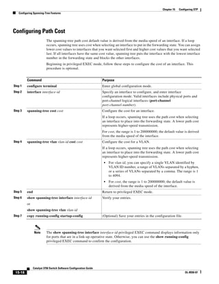
![15-19
Catalyst 3750 Switch Software Configuration Guide
OL-8550-07
Chapter 15 Configuring STP
Configuring Spanning-Tree Features
To return to the default setting, use the no spanning-tree [vlan vlan-id] cost interface configuration
command. For information on how to configure load sharing on trunk ports by using spanning-tree path
costs, see the “Configuring Trunk Ports for Load Sharing” section on page 12-20.
Configuring the Switch Priority of a VLAN
You can configure the switch priority and make it more likely that the switch will be chosen as the
root switch.
Note Exercise care when using this command. For most situations, we recommend that you use the
spanning-tree vlan vlan-id root primary and the spanning-tree vlan vlan-id root secondary global
configuration commands to modify the switch priority.
Beginning in privileged EXEC mode, follow these steps to configure the switch priority of a VLAN.
This procedure is optional.
To return to the default setting, use the no spanning-tree vlan vlan-id priority global configuration
command.
Command Purpose
Step 1 configure terminal Enter global configuration mode.
Step 2 spanning-tree vlan vlan-id priority priority Configure the switch priority of a VLAN.
• For vlan-id, you can specify a single VLAN identified by
VLAN ID number, a range of VLANs separated by a
hyphen, or a series of VLANs separated by a comma. The
range is 1 to 4094.
• For priority, the range is 0 to 61440 in increments of
4096; the default is 32768. The lower the number, the
more likely the switch will be chosen as the root switch.
Valid priority values are 4096, 8192, 12288, 16384,
20480, 24576, 28672, 32768, 36864, 40960, 45056,
49152, 53248, 57344, and 61440. All other values are
rejected.
Step 3 end Return to privileged EXEC mode.
Step 4 show spanning-tree vlan vlan-id Verify your entries.
Step 5 copy running-config startup-config (Optional) Save your entries in the configuration file.](https://image.slidesharecdn.com/2960scg-150701081942-lva1-app6891/85/Cisco-2960-Switch-Configuration-383-320.jpg)
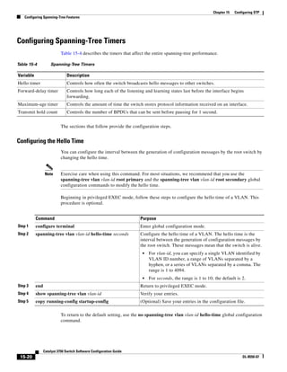
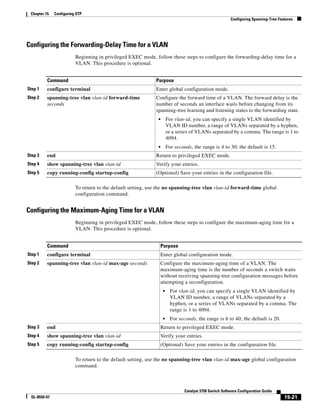
![15-22
Catalyst 3750 Switch Software Configuration Guide
OL-8550-07
Chapter 15 Configuring STP
Displaying the Spanning-Tree Status
Configuring the Transmit Hold-Count
You can configure the BPDU burst size by changing the transmit hold count value.
Note Changing this parameter to a higher value can have a significant impact on CPU utilization, especially
in Rapid-PVST mode. Lowering this value can slow down convergence in certain scenarios. We
recommend that you maintain the default setting.
Beginning in privileged EXEC mode, follow these steps to configure the transmit hold-count. This
procedure is optional.
To return to the default setting, use the no spanning-tree transmit hold-count value global
configuration command.
Displaying the Spanning-Tree Status
To display the spanning-tree status, use one or more of the privileged EXEC commands in Table 15-5:
You can clear spanning-tree counters by using the clear spanning-tree [interface interface-id]
privileged EXEC command.
For information about other keywords for the show spanning-tree privileged EXEC command, see the
command reference for this release.
Command Purpose
Step 1 configure terminal Enter global configuration mode.
Step 2 spanning-tree transmit hold-count value Configure the number of BPDUs that can be sent before pausing
for 1 second.
For value, the range is 1 to 20; the default is 6.
Step 3 end Return to privileged EXEC mode.
Step 4 show spanning-tree detail Verify your entries.
Step 5 copy running-config startup-config (Optional) Save your entries in the configuration file.
Table 15-5 Commands for Displaying Spanning-Tree Status
Command Purpose
show spanning-tree active Displays spanning-tree information on active interfaces only.
show spanning-tree detail Displays a detailed summary of interface information.
show spanning-tree interface interface-id Displays spanning-tree information for the specified interface.
show spanning-tree summary [totals] Displays a summary of interface states or displays the total lines of the STP
state section.](https://image.slidesharecdn.com/2960scg-150701081942-lva1-app6891/85/Cisco-2960-Switch-Configuration-386-320.jpg)
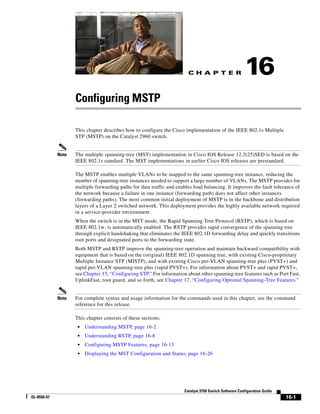
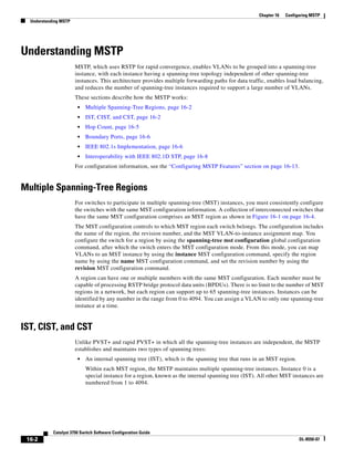
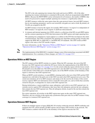
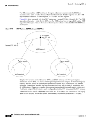
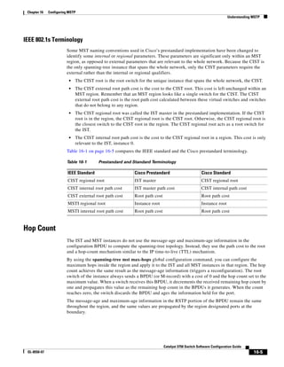
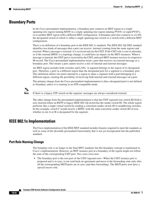
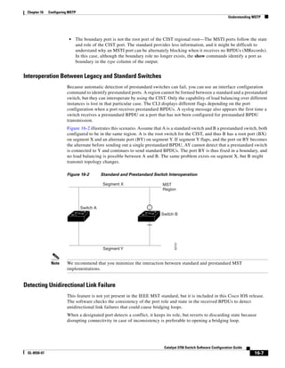
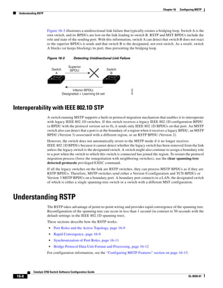
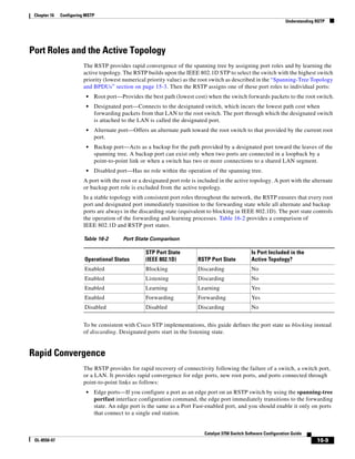

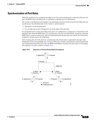
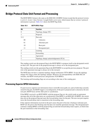
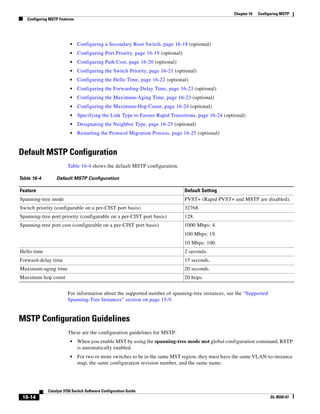
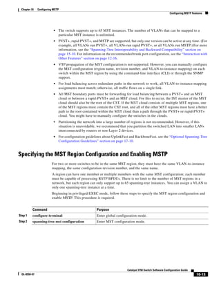
![16-16
Catalyst 3750 Switch Software Configuration Guide
OL-8550-07
Chapter 16 Configuring MSTP
Configuring MSTP Features
To return to the default MST region configuration, use the no spanning-tree mst configuration global
configuration command. To return to the default VLAN-to-instance map, use the no instance
instance-id [vlan vlan-range] MST configuration command. To return to the default name, use the no
name MST configuration command. To return to the default revision number, use the no revision MST
configuration command. To re-enable PVST+, use the no spanning-tree mode or the spanning-tree
mode pvst global configuration command.
This example shows how to enter MST configuration mode, map VLANs 10 to 20 to MST instance 1,
name the region region1, set the configuration revision to 1, display the pending configuration, apply
the changes, and return to global configuration mode:
Switch(config)# spanning-tree mst configuration
Switch(config-mst)# instance 1 vlan 10-20
Switch(config-mst)# name region1
Switch(config-mst)# revision 1
Switch(config-mst)# show pending
Pending MST configuration
Name [region1]
Revision 1
Instance Vlans Mapped
-------- ---------------------
Step 3 instance instance-id vlan vlan-range Map VLANs to an MST instance.
• For instance-id, the range is 0 to 4094.
• For vlan vlan-range, the range is 1 to 4094.
When you map VLANs to an MST instance, the mapping is
incremental, and the VLANs specified in the command are added to
or removed from the VLANs that were previously mapped.
To specify a VLAN range, use a hyphen; for example, instance 1 vlan
1-63 maps VLANs 1 through 63 to MST instance 1.
To specify a VLAN series, use a comma; for example, instance 1 vlan
10, 20, 30 maps VLANs 10, 20, and 30 to MST instance 1.
Step 4 name name Specify the configuration name. The name string has a maximum length
of 32 characters and is case sensitive.
Step 5 revision version Specify the configuration revision number. The range is 0 to 65535.
Step 6 show pending Verify your configuration by displaying the pending configuration.
Step 7 exit Apply all changes, and return to global configuration mode.
Step 8 spanning-tree mode mst Enable MSTP. RSTP is also enabled.
Caution Changing spanning-tree modes can disrupt traffic because all
spanning-tree instances are stopped for the previous mode and
restarted in the new mode.
You cannot run both MSTP and PVST+ or both MSTP and rapid PVST+
at the same time.
Step 9 end Return to privileged EXEC mode.
Step 10 show running-config Verify your entries.
Step 11 copy running-config startup-config (Optional) Save your entries in the configuration file.
Command Purpose](https://image.slidesharecdn.com/2960scg-150701081942-lva1-app6891/85/Cisco-2960-Switch-Configuration-402-320.jpg)
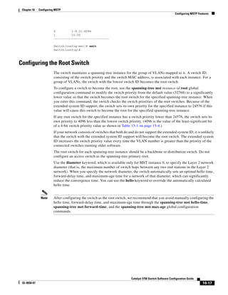
![16-18
Catalyst 3750 Switch Software Configuration Guide
OL-8550-07
Chapter 16 Configuring MSTP
Configuring MSTP Features
Beginning in privileged EXEC mode, follow these steps to configure a switch as the root switch. This
procedure is optional.
To return the switch to its default setting, use the no spanning-tree mst instance-id root global
configuration command.
Configuring a Secondary Root Switch
When you configure a switch with the extended system ID support as the secondary root, the switch
priority is modified from the default value (32768) to 28672. The switch is then likely to become the
root switch for the specified instance if the primary root switch fails. This is assuming that the other
network switches use the default switch priority of 32768 and therefore are unlikely to become the root
switch.
You can execute this command on more than one switch to configure multiple backup root switches. Use
the same network diameter and hello-time values that you used when you configured the primary root
switch with the spanning-tree mst instance-id root primary global configuration command.
Command Purpose
Step 1 configure terminal Enter global configuration mode.
Step 2 spanning-tree mst instance-id root primary
[diameter net-diameter [hello-time seconds]]
Configure a switch as the root switch.
• For instance-id, you can specify a single instance, a range
of instances separated by a hyphen, or a series of instances
separated by a comma. The range is 0 to 4094.
• (Optional) For diameter net-diameter, specify the
maximum number of switches between any two end
stations. The range is 2 to 7. This keyword is available
only for MST instance 0.
• (Optional) For hello-time seconds, specify the interval in
seconds between the generation of configuration messages
by the root switch. The range is 1 to 10 seconds; the
default is 2 seconds.
Step 3 end Return to privileged EXEC mode.
Step 4 show spanning-tree mst instance-id Verify your entries.
Step 5 copy running-config startup-config (Optional) Save your entries in the configuration file.](https://image.slidesharecdn.com/2960scg-150701081942-lva1-app6891/85/Cisco-2960-Switch-Configuration-404-320.jpg)
![16-19
Catalyst 3750 Switch Software Configuration Guide
OL-8550-07
Chapter 16 Configuring MSTP
Configuring MSTP Features
Beginning in privileged EXEC mode, follow these steps to configure a switch as the secondary root
switch. This procedure is optional.
To return the switch to its default setting, use the no spanning-tree mst instance-id root global
configuration command.
Configuring Port Priority
If a loop occurs, the MSTP uses the port priority when selecting an interface to put into the forwarding
state. You can assign higher priority values (lower numerical values) to interfaces that you want selected
first and lower priority values (higher numerical values) that you want selected last. If all interfaces have
the same priority value, the MSTP puts the interface with the lowest interface number in the forwarding
state and blocks the other interfaces.
Beginning in privileged EXEC mode, follow these steps to configure the MSTP port priority of an
interface. This procedure is optional.
Command Purpose
Step 1 configure terminal Enter global configuration mode.
Step 2 spanning-tree mst instance-id root
secondary [diameter net-diameter
[hello-time seconds]]
Configure a switch as the secondary root switch.
• For instance-id, you can specify a single instance, a range of
instances separated by a hyphen, or a series of instances
separated by a comma. The range is 0 to 4094.
• (Optional) For diameter net-diameter, specify the maximum
number of switches between any two end stations. The range is 2
to 7. This keyword is available only for MST instance 0.
• (Optional) For hello-time seconds, specify the interval in
seconds between the generation of configuration messages by
the root switch. The range is 1 to 10 seconds; the default
is 2 seconds.
Use the same network diameter and hello-time values that you used
when configuring the primary root switch. See the “Configuring the
Root Switch” section on page 16-17.
Step 3 end Return to privileged EXEC mode.
Step 4 show spanning-tree mst instance-id Verify your entries.
Step 5 copy running-config startup-config (Optional) Save your entries in the configuration file.
Command Purpose
Step 1 configure terminal Enter global configuration mode.
Step 2 interface interface-id Specify an interface to configure, and enter interface
configuration mode.
Valid interfaces include physical ports and port-channel
logical interfaces. The port-channel range is 1 to 6.](https://image.slidesharecdn.com/2960scg-150701081942-lva1-app6891/85/Cisco-2960-Switch-Configuration-405-320.jpg)
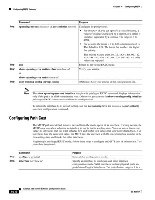
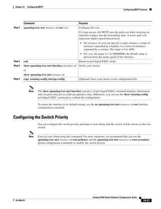
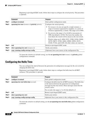
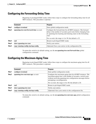
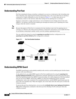
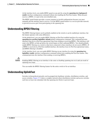
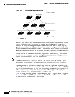
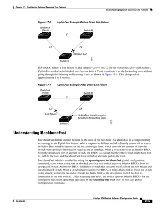
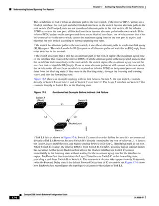
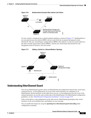
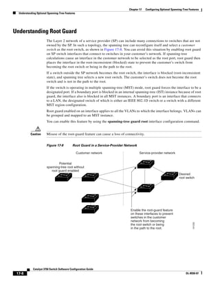
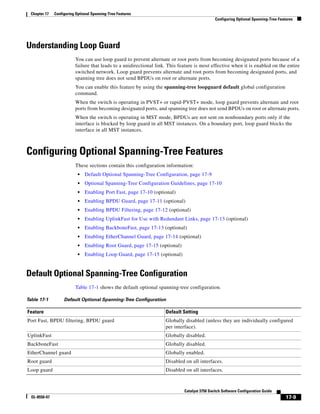
![17-10
Catalyst 3750 Switch Software Configuration Guide
OL-8550-07
Chapter 17 Configuring Optional Spanning-Tree Features
Configuring Optional Spanning-Tree Features
Optional Spanning-Tree Configuration Guidelines
You can configure PortFast, BPDU guard, BPDU filtering, EtherChannel guard, root guard, or loop
guard if your switch is running PVST+, rapid PVST+, or MSTP.
You can configure the UplinkFast or the BackboneFast feature for rapid PVST+ or for the MSTP, but the
feature remains disabled (inactive) until you change the spanning-tree mode to PVST+.
Enabling Port Fast
An interface with the Port Fast feature enabled is moved directly to the spanning-tree forwarding state
without waiting for the standard forward-time delay.
Caution Use Port Fast only when connecting a single end station to an access or trunk port. Enabling this feature
on an interface connected to a switch or hub could prevent spanning tree from detecting and disabling
loops in your network, which could cause broadcast storms and address-learning problems.
If you enable the voice VLAN feature, the Port Fast feature is automatically enabled. When you disable
voice VLAN, the Port Fast feature is not automatically disabled. For more information, see Chapter 14,
“Configuring Voice VLAN.”
You can enable this feature if your switch is running PVST+, rapid PVST+, or MSTP.
Beginning in privileged EXEC mode, follow these steps to enable Port Fast. This procedure is optional.
Command Purpose
Step 1 configure terminal Enter global configuration mode.
Step 2 interface interface-id Specify an interface to configure, and enter interface
configuration mode.
Step 3 spanning-tree portfast [trunk] Enable Port Fast on an access port connected to a single
workstation or server. By specifying the trunk keyword, you can
enable Port Fast on a trunk port.
Note To enable Port Fast on trunk ports, you must use the
spanning-tree portfast trunk interface configuration
command. The spanning-tree portfast command will
not work on trunk ports.
Caution Make sure that there are no loops in the network
between the trunk port and the workstation or server
before you enable Port Fast on a trunk port.
By default, Port Fast is disabled on all interfaces.
Step 4 end Return to privileged EXEC mode.
Step 5 show spanning-tree interface interface-id
portfast
Verify your entries.
Step 6 copy running-config startup-config (Optional) Save your entries in the configuration file.](https://image.slidesharecdn.com/2960scg-150701081942-lva1-app6891/85/Cisco-2960-Switch-Configuration-422-320.jpg)
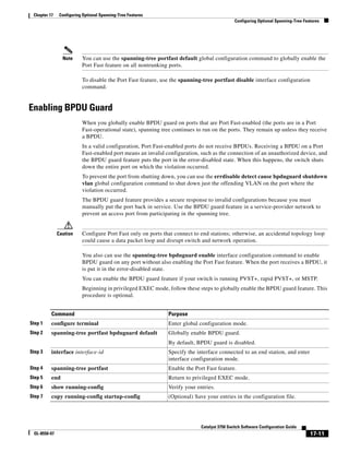
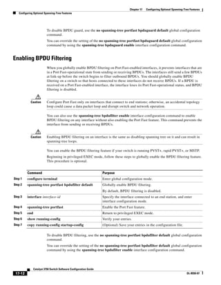
![17-13
Catalyst 3750 Switch Software Configuration Guide
OL-8550-07
Chapter 17 Configuring Optional Spanning-Tree Features
Configuring Optional Spanning-Tree Features
Enabling UplinkFast for Use with Redundant Links
UplinkFast cannot be enabled on VLANs that have been configured with a switch priority. To enable
UplinkFast on a VLAN with switch priority configured, first restore the switch priority on the VLAN to
the default value by using the no spanning-tree vlan vlan-id priority global configuration command.
Note When you enable UplinkFast, it affects all VLANs on the switch. You cannot configure UplinkFast on
an individual VLAN.
You can configure the UplinkFast feature for rapid PVST+ or for the MSTP, but the feature remains
disabled (inactive) until you change the spanning-tree mode to PVST+.
Beginning in privileged EXEC mode, follow these steps to enable UplinkFast. This procedure is
optional.
When UplinkFast is enabled, the switch priority of all VLANs is set to 49152. If you change the path
cost to a value less than 3000 and you enable UplinkFast or UplinkFast is already enabled, the path cost
of all interfaces and VLAN trunks is increased by 3000 (if you change the path cost to 3000 or above,
the path cost is not altered). The changes to the switch priority and the path cost reduce the chance that
a switch will become the root switch.
When UplinkFast is disabled, the switch priorities of all VLANs and path costs of all interfaces are set
to default values if you did not modify them from their defaults.
To return the update packet rate to the default setting, use the no spanning-tree uplinkfast
max-update-rate global configuration command. To disable UplinkFast, use the no spanning-tree
uplinkfast command.
Enabling BackboneFast
You can enable BackboneFast to detect indirect link failures and to start the spanning-tree
reconfiguration sooner.
Note If you use BackboneFast, you must enable it on all switches in the network. BackboneFast is not
supported on Token Ring VLANs. This feature is supported for use with third-party switches.
Command Purpose
Step 1 configure terminal Enter global configuration mode.
Step 2 spanning-tree uplinkfast [max-update-rate
pkts-per-second]
Enable UplinkFast.
(Optional) For pkts-per-second, the range is 0 to 32000 packets per
second; the default is 150.
If you set the rate to 0, station-learning frames are not generated,
and the spanning-tree topology converges more slowly after a loss
of connectivity.
Step 3 end Return to privileged EXEC mode.
Step 4 show spanning-tree summary Verify your entries.
Step 5 copy running-config startup-config (Optional) Save your entries in the configuration file.](https://image.slidesharecdn.com/2960scg-150701081942-lva1-app6891/85/Cisco-2960-Switch-Configuration-425-320.jpg)
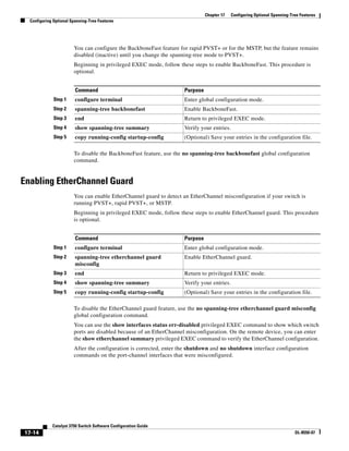
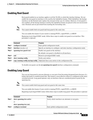
![17-16
Catalyst 3750 Switch Software Configuration Guide
OL-8550-07
Chapter 17 Configuring Optional Spanning-Tree Features
Displaying the Spanning-Tree Status
To globally disable loop guard, use the no spanning-tree loopguard default global configuration
command. You can override the setting of the no spanning-tree loopguard default global configuration
command by using the spanning-tree guard loop interface configuration command.
Displaying the Spanning-Tree Status
To display the spanning-tree status, use one or more of the privileged EXEC commands in Table 17-2:
You can clear spanning-tree counters by using the clear spanning-tree [interface interface-id]
privileged EXEC command.
For information about other keywords for the show spanning-tree privileged EXEC command, see the
command reference for this release.
Step 3 spanning-tree loopguard default Enable loop guard.
By default, loop guard is disabled.
Step 4 end Return to privileged EXEC mode.
Step 5 show running-config Verify your entries.
Step 6 copy running-config startup-config (Optional) Save your entries in the configuration file.
Command Purpose
Table 17-2 Commands for Displaying the Spanning-Tree Status
Command Purpose
show spanning-tree active Displays spanning-tree information on active interfaces only.
show spanning-tree detail Displays a detailed summary of interface information.
show spanning-tree interface interface-id Displays spanning-tree information for the specified interface.
show spanning-tree mst interface interface-id Displays MST information for the specified interface.
show spanning-tree summary [totals] Displays a summary of interface states or displays the total lines of the
spanning-tree state section.](https://image.slidesharecdn.com/2960scg-150701081942-lva1-app6891/85/Cisco-2960-Switch-Configuration-428-320.jpg)
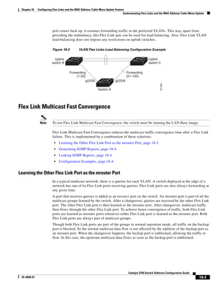
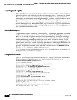
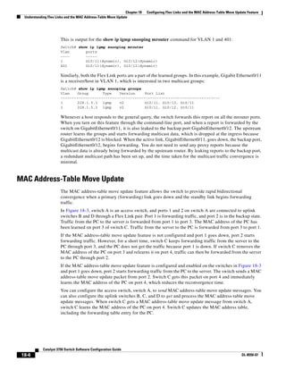
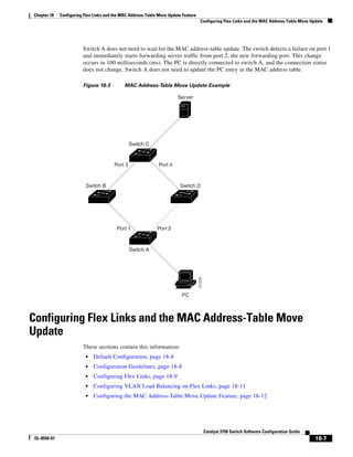
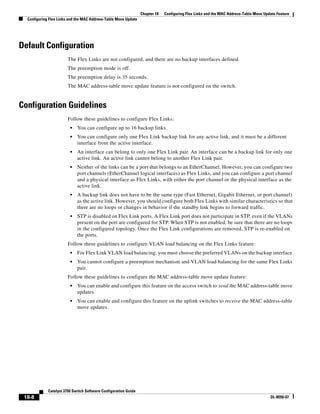
![18-9
Catalyst 3750 Switch Software Configuration Guide
OL-8550-07
Chapter 18 Configuring Flex Links and the MAC Address-Table Move Update Feature
Configuring Flex Links and the MAC Address-Table Move Update
Configuring Flex Links
Beginning in privileged EXEC mode, follow these steps to configure a pair of Flex Links:
To disable a Flex Link backup interface, use the no switchport backup interface interface-id interface
configuration command.
This example shows how to configure an interface with a backup interface and to verify the
configuration:
Switch# configure terminal
Switch(conf)# interface gigabitethernet0/1
Switch(conf-if)# switchport backup interface gigabitethernet0/2
Switch(conf-if)# end
Switch# show interfaces switchport backup
Switch Backup Interface Pairs:
Active Interface Backup Interface State
------------------------------------------------------------------------
GigabitEthernet0/1 GigabitEthernet0/3 Active Standby/Backup Up
Vlans Preferred on Active Interface: 1-3,5-4094
Vlans Preferred on Backup Interface: 4
Beginning in privileged EXEC mode, follow these steps to configure a preemption scheme for a pair of
Flex Links:
Command Purpose
Step 1 configure terminal Enter global configuration mode.
Step 2 interface interface-id Specify the interface, and enter interface configuration
mode. The interface can be a physical Layer 2 interface or
a port channel (logical interface). The port-channel range
is 1 to 6.
Step 3 switchport backup interface interface-id Configure a physical Layer 2 interface (or port channel)
as part of a Flex Link pair with the interface. When one
link is forwarding traffic, the other interface is in standby
mode.
Step 4 end Return to privileged EXEC mode.
Step 5 show interfaces [interface-id] switchport backup Verify the configuration.
Step 6 copy running-config startup config (Optional) Save your entries in the switch startup
configuration file.
Command Purpose
Step 1 configure terminal Enter global configuration mode.
Step 2 interface interface-id Specify the interface, and enter interface configuration
mode. The interface can be a physical Layer 2 interface or
a port channel (logical interface). The port-channel range
is 1 to 6.](https://image.slidesharecdn.com/2960scg-150701081942-lva1-app6891/85/Cisco-2960-Switch-Configuration-437-320.jpg)
![18-10
Catalyst 3750 Switch Software Configuration Guide
OL-8550-07
Chapter 18 Configuring Flex Links and the MAC Address-Table Move Update Feature
Configuring Flex Links and the MAC Address-Table Move Update
To remove a preemption scheme, use the no switchport backup interface interface-id preemption
mode interface configuration command. To reset the delay time to the default, use the no switchport
backup interface interface-id preemption delay interface configuration command.
This example shows how to configure the preemption mode as forced for a backup interface pair and to
verify the configuration:
Switch# configure terminal
Switch(conf)# interface gigabitethernet0/1
Switch(conf-if)#switchport backup interface gigabitethernet0/2 preemption mode forced
Switch(conf-if)#switchport backup interface gigabitethernet0/2 preemption delay 50
Switch(conf-if)# end
Switch# show interfaces switchport backup detail
Active Interface Backup Interface State
------------------------------------------------------------------------
GigabitEthernet0/21 GigabitEthernet0/2 Active Up/Backup Standby
Interface Pair : Gi0/1, Gi0/2
Preemption Mode : forced
Preemption Delay : 50 seconds
Bandwidth : 100000 Kbit (Gi0/1), 100000 Kbit (Gi0/2)
Mac Address Move Update Vlan : auto
Step 3 switchport backup interface interface-id Configure a physical Layer 2 interface (or port channel)
as part of a Flex Links pair with the interface. When one
link is forwarding traffic, the other interface is in standby
mode.
Step 4 switchport backup interface interface-id preemption
mode [forced | bandwidth | off]
Configure a preemption mechanism and delay for a Flex
Link interface pair. You can configure the preemption as:
• Forced—the active interface always preempts the
backup.
• Bandwidth—the interface with the higher bandwidth
always acts as the active interface.
• Off—no preemption happens from active to backup.
Step 5 switchport backup interface interface-id preemption
delay delay-time
Configure the time delay until a port preempts another
port.
Note Setting a delay time only works with forced and
bandwidth modes.
Step 6 end Return to privileged EXEC mode.
Step 7 show interfaces [interface-id] switchport backup Verify the configuration.
Step 8 copy running-config startup config (Optional) Save your entries in the switch startup
configuration file.
Command Purpose](https://image.slidesharecdn.com/2960scg-150701081942-lva1-app6891/85/Cisco-2960-Switch-Configuration-438-320.jpg)
![18-11
Catalyst 3750 Switch Software Configuration Guide
OL-8550-07
Chapter 18 Configuring Flex Links and the MAC Address-Table Move Update Feature
Configuring Flex Links and the MAC Address-Table Move Update
Configuring VLAN Load Balancing on Flex Links
Beginning in privileged EXEC mode, follow these steps to configure VLAN load balancing on Flex
Links:
To disable the VLAN load balancing feature, use the no switchport backup interface interface-id
prefer vlan vlan-range interface configuration command.
In the following example, VLANs 1 to 50, 60, and 100 to 120 are configured on the switch:
Switch(config)#interface gigabitethernet 0/6
Switch(config-if)#switchport backup interface gigabitethernet 0/8 prefer vlan 60,100-120
When both interfaces are up, Gi0/8 forwards traffic for VLANs 60 and 100 to 120, and Gi0/6 forwards
traffic for VLANs 1 to 50.
Switch#show interfaces switchport backup
Switch Backup Interface Pairs:
Active Interface Backup Interface State
------------------------------------------------------------------------
GigabitEthernet0/6 GigabitEthernet0/8 Active Up/Backup Up
Vlans Preferred on Active Interface: 1-50
Vlans Preferred on Backup Interface: 60, 100-120
When a Flex Link interface goes down (LINK_DOWN), VLANs preferred on this interface are moved
to the peer interface of the Flex Link pair. In this example, if interface Gi0/6 goes down, Gi0/8 carries
all VLANs of the Flex Link pair.
Switch#show interfaces switchport backup
Switch Backup Interface Pairs:
Active Interface Backup Interface State
------------------------------------------------------------------------
GigabitEthernet0/6 GigabitEthernet0/8 Active Down/Backup Up
Vlans Preferred on Active Interface: 1-50
Vlans Preferred on Backup Interface: 60, 100-120
Command Purpose
Step 1 configure terminal Enter global configuration mode.
Step 2 interface interface-id Specify the interface, and enter interface configuration
mode. The interface can be a physical Layer 2 interface or
a port channel (logical interface). The port-channel range
is 1 to 6.
Step 3 switchport backup interface interface-id prefer vlan
vlan-range
Configure a physical Layer 2 interface (or port channel)
as part of a Flex Links pair with the interface, and specify
the VLANs carried on the interface. The VLAN ID range
is 1 to 4094.
Step 4 end Return to privileged EXEC mode.
Step 5 show interfaces [interface-id] switchport backup Verify the configuration.
Step 6 copy running-config startup config (Optional) Save your entries in the switch startup
configuration file.](https://image.slidesharecdn.com/2960scg-150701081942-lva1-app6891/85/Cisco-2960-Switch-Configuration-439-320.jpg)
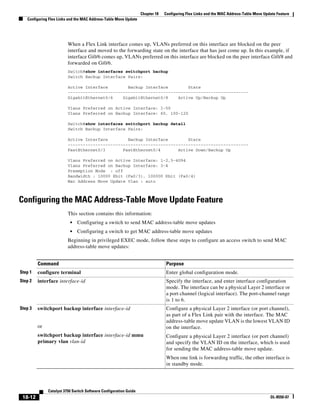
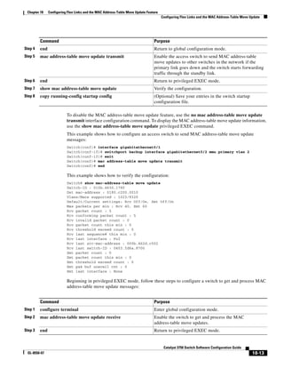
![18-14
Catalyst 3750 Switch Software Configuration Guide
OL-8550-07
Chapter 18 Configuring Flex Links and the MAC Address-Table Move Update Feature
Monitoring Flex Links and the MAC Address-Table Move Update
To disable the MAC address-table move update feature, use the no mac address-table move update
receive configuration command. To display the MAC address-table move update information, use the
show mac address-table move update privileged EXEC command.
This example shows how to configure a switch to get and process MAC address-table move update
messages:
Switch# configure terminal
Switch(conf)# mac address-table move update receive
Switch(conf)# end
Monitoring Flex Links and the MAC Address-Table
Move Update
Table 18-1 shows the privileged EXEC commands for monitoring the Flex Links configuration and the
MAC address-table move update information.
Step 4 show mac address-table move update Verify the configuration.
Step 5 copy running-config startup config (Optional) Save your entries in the switch startup
configuration file.
Command Purpose
Table 18-1 Flex Links and MAC Address-Table Move Update Monitoring Commands
Command Purpose
show interfaces [interface-id] switchport
backup
Displays the Flex Link backup interface configured for an interface or all the
configured Flex Links and the state of each active and backup interface (up
or standby mode). When VLAN load balancing is enabled, the output
displays the preferred VLANS on Active and Backup interfaces.
show mac address-table move update Displays the MAC address-table move update information on the switch.](https://image.slidesharecdn.com/2960scg-150701081942-lva1-app6891/85/Cisco-2960-Switch-Configuration-442-320.jpg)
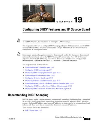
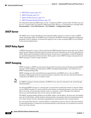
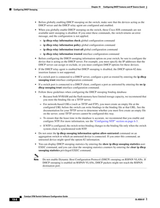
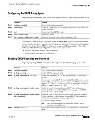
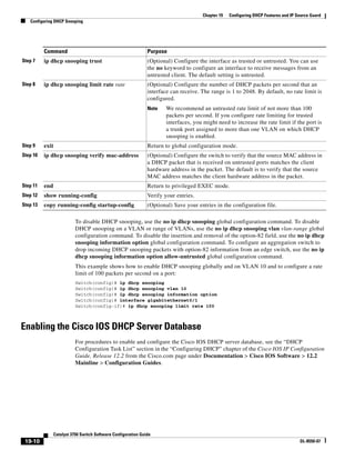
![19-11
Catalyst 3750 Switch Software Configuration Guide
OL-8550-07
Chapter 19 Configuring DHCP Features and IP Source Guard
Configuring DHCP Snooping
Enabling the DHCP Snooping Binding Database Agent
Beginning in privileged EXEC mode, follow these steps to enable and configure the DHCP snooping
binding database agent on the switch:
To stop using the database agent and binding files, use the no ip dhcp snooping database global
configuration command. To reset the timeout or delay values, use the ip dhcp snooping database
timeout seconds or the ip dhcp snooping database write-delay seconds global configuration
command.
To clear the statistics of the DHCP snooping binding database agent, use the clear ip dhcp snooping
database statistics privileged EXEC command. To renew the database, use the renew ip dhcp
snooping database privileged EXEC command.
To delete binding entries from the DHCP snooping binding database, use the no ip dhcp snooping
binding mac-address vlan vlan-id ip-address interface interface-id privileged EXEC command. Enter
this command for each entry that you want to delete.
Command Purpose
Step 1 configure terminal Enter global configuration mode.
Step 2 ip dhcp snooping database
{flash:/filename |
ftp://user:password@host/filename |
http://[[username:password]@]{hostna
me | host-ip}[/directory]
/image-name.tar |
rcp://user@host/filename}|
tftp://host/filename
Specify the URL for the database agent or the binding file by using one
of these forms:
• flash:/filename
• ftp://user:password@host/filename
• http://[[username:password]@]{hostname | host-ip}[/directory]
/image-name.tar
• rcp://user@host/filename
• tftp://host/filename
Step 3 ip dhcp snooping database timeout
seconds
Specify (in seconds) how long to wait for the database transfer process to
finish before stopping the process.
The default is 300 seconds. The range is 0 to 86400. Use 0 to define an
infinite duration, which means to continue trying the transfer
indefinitely.
Step 4 ip dhcp snooping database write-delay
seconds
Specify the duration for which the transfer should be delayed after the
binding database changes. The range is from 15 to 86400 seconds. The
default is 300 seconds (5 minutes).
Step 5 end Return to privileged EXEC mode.
Step 6 ip dhcp snooping binding mac-address
vlan vlan-id ip-address interface
interface-id expiry seconds
(Optional) Add binding entries to the DHCP snooping binding database.
The vlan-id range is from 1 to 4904. The seconds range is from 1 to
4294967295.
Enter this command for each entry that you add.
Note Use this command when you are testing or debugging the switch.
Step 7 show ip dhcp snooping database
[detail]
Display the status and statistics of the DHCP snooping binding database
agent.
Step 8 copy running-config startup-config (Optional) Save your entries in the configuration file.](https://image.slidesharecdn.com/2960scg-150701081942-lva1-app6891/85/Cisco-2960-Switch-Configuration-453-320.jpg)
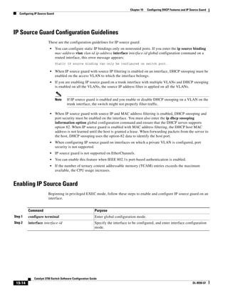
![19-15
Catalyst 3750 Switch Software Configuration Guide
OL-8550-07
Chapter 19 Configuring DHCP Features and IP Source Guard
Configuring IP Source Guard
To disable IP source guard with source IP address filtering, use the no ip verify source interface
configuration command.
To delete a static IP source binding entry, use the no ip source global configuration command.
This example shows how to enable IP source guard with source IP and MAC filtering on VLANs 10
and 11:
Switch# configure terminal
Enter configuration commands, one per line. End with CNTL/Z.
Switch(config)# interface gigabitethernet0/1
Switch(config-if)# ip verify source port-security
Switch(config-if)# exit
Switch(config)# ip source binding 0100.0022.0010 vlan 10 10.0.0.2 interface
gigabitethernet0/1
Switch(config)# ip source binding 0100.0230.0002 vlan 11 10.0.0.4 interface
gigabitethernet0/1
Switch(config)# end
Step 3 ip verify source
or
ip verify source port-security
Enable IP source guard with source IP address filtering.
Enable IP source guard with source IP and MAC address filtering.
Note When you enable both IP Source Guard and Port Security by
using the ip verify source port-security interface configuration
command, there are two caveats:
• The DHCP server must support option 82, or the client is not
assigned an IP address.
• The MAC address in the DHCP packet is not learned as a secure
address. The MAC address of the DHCP client is learned as a
secure address only when the switch receives non-DHCP data
traffic.
Step 4 exit Return to global configuration mode.
Step 5 ip source binding mac-address vlan
vlan-id ip-address inteface interface-id
Add a static IP source binding.
Enter this command for each static binding.
Step 6 end Return to privileged EXEC mode.
Step 7 show ip verify source [interface
interface-id]
Display the IP source guard configuration for all interfaces or for a
specific interface.
Step 8 show ip source binding [ip-address]
[mac-address] [dhcp-snooping | static]
[inteface interface-id] [vlan vlan-id]
Display the IP source bindings on the switch, on a specific VLAN, or on
a specific interface.
Step 9 copy running-config startup-config (Optional) Save your entries in the configuration file.
Command Purpose](https://image.slidesharecdn.com/2960scg-150701081942-lva1-app6891/85/Cisco-2960-Switch-Configuration-457-320.jpg)

![19-18
Catalyst 3750 Switch Software Configuration Guide
OL-8550-07
Chapter 19 Configuring DHCP Features and IP Source Guard
Configuring DHCP Server Port-Based Address Allocation
To disable DHCP port-based address allocation, use the no ip dhcp use subscriber-id client-id global
configuration command. To disable the automatic generation of a subscriber identifier, use the no ip
dhcp subscriber-id interface-name global configuration command. To disable the subscriber identifier
on an interface, use the no ip dhcp server use subscriber-id client-id interface configuration command.
To remove an IP address reservation from a DHCP pool, use the no address ip-address client-id string
DHCP pool configuration command.
In this example, a subscriber identifier is automatically generated, and the DHCP server ignores any
client identifier fields in the DHCP messages and uses the subscriber identifier instead. The subscriber
identifier is based on the short name of the interface and the client preassigned IP address 10.1.1.7.
switch# show running config
Building configuration...
Current configuration : 4899 bytes
!
version 12.2
!
hostname switch
!
no aaa new-model
clock timezone EST 0
ip subnet-zero
ip dhcp relay information policy removal pad
no ip dhcp use vrf connected
ip dhcp use subscriber-id client-id
ip dhcp subscriber-id interface-name
ip dhcp excluded-address 10.1.1.1 10.1.1.3
!
ip dhcp pool dhcppool
network 10.1.1.0 255.255.255.0
address 10.1.1.7 client-id “Et1/0” ascii
<output truncated>
This example shows that the preassigned address was correctly reserved in the DHCP pool:
switch# show ip dhcp pool dhcppool
Pool dhcp pool:
Utilization mark (high/low) : 100 / 0
Command Purpose
Step 1 configure terminal Enter global configuration mode.
Step 2 ip dhcp pool poolname Enter DHCP pool configuration mode, and define the
name for the DHCP pool. The pool name can be a
symbolic string (such as Engineering) or an integer
(such as 0).
Step 3 network network-number [mask | /prefix-length] Specify the subnet network number and mask of the
DHCP address pool.
Step 4 address ip-address client-id string [ascii] Reserve an IP address for a DHCP client identified by
the interface name.
string—can be an ASCII value or a hexadecimal
value.
Step 5 end Return to privileged EXEC mode.
Step 6 show ip dhcp pool Verify DHCP pool configuration.
Step 7 copy running-config startup-config (Optional) Save your entries in the configuration file.](https://image.slidesharecdn.com/2960scg-150701081942-lva1-app6891/85/Cisco-2960-Switch-Configuration-460-320.jpg)