Downloaded 506 times
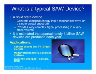

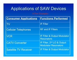


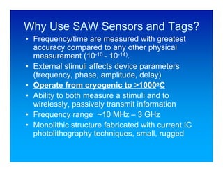
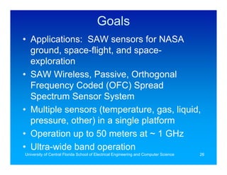
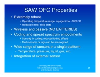
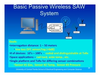
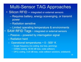


The document discusses Surface Acoustic Wave (SAW) wireless passive RF sensor systems developed at the University of Central Florida, highlighting over 25 years of research in communication devices, new piezoelectric materials, and sensors. It outlines the unique capabilities and applications of SAW technology in various fields, including military and consumer electronics, emphasizing the development of wireless, passive sensors capable of high accuracy and significant operational ranges. Key features include robustness, low power requirements, and the ability to measure various environmental variables, making them suitable for diverse applications like NASA and space exploration.


![Story Lab - Sensor Journalism [23-04-2015, Liège]](https://cdn.slidesharecdn.com/ss_thumbnails/storylab-2015-04-23-150423042135-conversion-gate01-thumbnail.jpg?width=640&height=640&fit=bounds)