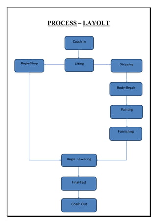
CONTENTS
1. Introduction
2. Process Layout
3. Shops :
i. Lifting Shop
ii. Stripping Shop
iii. Body Repair Shop
iv. Shell Component Shop
v. Carpentry Shop
vi. Paint Shop
vii. Furnishing Shop
viii. ETL Shop
ix. Wheel Shop
x. Bogie Shop
xi. Air Brake Shop
4. Ancillary Shops
i. Mill Wright Shop
ii. Shell Component Shop
iii. Electrical Repair Shop
iv. Laboratory
5. Achievements.
INTRODUCTION
Indian Railways is a means by which 12.5 million people travels every day. In this overall
chaos planned maintenance and repair of the coaches is essentially important in order to
avoid any accident.In 1947 first Integral Coach Factory was established with the help of
Switzerland.
In the year 1989 Coach Rehabilitation WorkShop (CRWS) Bhopal was established.The basic
work here at CRWS is rebuilding the coach in their mid life.The life cycle of a coach is
generally about 25 years but due to corrosion of various parts the coach has to be condemned
in between, to avoid such things concept of MLR (Mid- Life Rehabilitation) was introduced
at CRWS.
salient MLR features
It has been estimated by Work Study that rehabilitation work content is nearly 4 times that of
normal POH. Normal POH does not include major corrosion repairs and takes about 2500
man-hours. Mid-life rehabilitation includes heavy corrosion repair and complete refurbishing
which takes about 10000 man hours (all items of POH are, in any case, covered). At present
this Workshop is capable of undertaking any type of ICF coach and BEML coach with ICF
Bogies.
The underlying principle of MLR is to give 'As New' condition to the coach at its mid life i.e.
when it is 12-15 years of age. Unlike in POH, the coach is completely stripped, heavy
corroded areas attended to, Fibre Glass Tissue re-laid/re-painted, necessary modifications
carried out and new furnishing is provided. It can be seen that while corrosion repair is
minimal attended to, during POH, in MLR it is completely attended to.
Main work here is the Corrosion Repair.
Causes of Corrosion in Indian Railway Coaches:
1. Water seepage through the flooring to the top of trough floor.
2. Leakage of water through lavatory flooring.
3. Missing of corrode chute and drain pipe.
4. Defective water pipe fittings.
5. Absence of surface preparation during replacement of commode and drain pipes.
6. Habits of flushing the flooring with the water jet for cleaning.
7. The condition of air trapped in between trough floor and flooring due to climate changes.
8. Striking of flying ballast when the train is running.
9. Design of window seal leaves the gap between the side panel to allow the rain water flow
through the panel and to drain out at the bottom.
10. Blockage of drain water by accumulated dust on top of trough floor.
Services Offered :
a) MLR of BG coaches (ICF, RCF & BEML with ICF Bogies) in the age group of 12-15
years.
b) MLR of AC Coaches.
c) MLR of Rajdhani Express Coaches.
d) MLR of end on generation coaches.
e) ART coaches under RSP programme.
f) IOH of Bogie/coaches.
BG coaches which are 12-15 years old are undertaken for complete corrosion repair &
refurbishing with retro-fitment of bogie mounted airbrake taking an average cycle time of 35
days.
PROCESS – LAYOUT
Bogie-Shop
Furnishing
Bogie- Lowering
Stripping
Painting
Body-Repair
Final-Test
Coach Out
Lifting
Coach In
PROCESS LAYOUT:
LIFTING:
First of all the coach is brought in the Lifting Shop where it is dismantled i.e. Boggie and
Shell are separated. The boggie which is separated is dismantled here and the bolster
assembly , LSS (lower spring sheet) shock absorber , transom, cross members and headstock
are removed.
Two cranes of capacity 25tonne/7.5 tonne are used. These operate in parallel. 25 tonne is
used for shell lifting and 7.5 tonne is used for boggie lifting. From thereon boggie is sent to
the Boggie Shop and Shell is taken to the Stripping Section via Dummy boggies.
STRIPPING :
To identify area of corrosion we strip out various parts such as berth, seat, wash basin, and
lower side panel is separated by using plasma cutter. Then it is moved to body reapair shop.
BODY REPAIR SHOP:
Intensive corrosion repair is done by replacing various parts such as welding new side panel
in the shell .this is done after checking for the thickness of the sheet if it is less than the
permissible value then it is replaced.
PAINTING :
Red oxide primer is used for anti corrosion coating. It is generally applied 12 hours before
puttying is done. After that various parts of coach are painted manually by hand or spray
paint.
FURNISHING :
Here the plywood flooring is done after that windows shutter are installed the roof ceiling is
done. Later on furnishing of berths and various other passenger amenities are installed along
with the lavatory fitting.
BOGGIE LOWERING :
Here the shell and the boggie are engaged using cranes. The shell is lowered on to the
finished boggie from boggie shop.
FINAL TEST:
The assembled coach is tested for tolerances and if found fit is dispatched from here and it
can be used as a passenger car then.
LIFTING SHOP
In the Lifting Shop the coach which is to be rehabilitated is brought first.
Then the dismantling of the coach is done by lifting cranes. The bogie and Shell
parts are separated using the two parallel operated cranes each of capacity 25
tonne/ 7.5 tonnes. When the shell is lifted the two cranes with 25 tonne capacity
are operated. And when the bogie has to be lifted the crane with 7.5 tonne
capacity is used. This is because the weight of the shell of a passenger car is
about 40- 50 tonnes and bogie’s weight is quite lower about 15 tonnes.
After lifting shell it is put over Dummy bogie and then centre pivot pin and side
bearers are also attended here then the shell is sent to the Stripping Shop.
And the bogie is sent to the Bogie Shop.
STRIPPING SHOP
Here the main motto is to identify the various corroded parts of the shell. To identify them
stripping of various components such as berths, wash basin, lavatory fittings, window
shutters, side panels, flooring, electrical auxiliary equipment etc. are removed manually by
hand operated tools or by weld cutters.
Out side view of stripped shell.
Inside view of shell after stripping.
BODY REPAIR SHOP
The stripped shell is brought to this shop. Here corroded parts are removed using Plasma
cutters and new parts from Shell components shop are welded in their respective places. The
side panels of lavatory portion are completely changed for each coach. As it is most prone to
moisture and eventually corrosion.
The sheets which are less than 5 mm thick are removed and replaced by new ones. The 2 mm
thick sheets are completely replaced.
Tub floors, sole bar, headstock, cross barrel, floor stepper are all supplied from shell
components shop and are fitted in the coach at their respective places.
The types of welding used are :
1. Gas welding (oxy acetylene)
2. TIG welding
3. Consumable electrode welding.
SHELL COMPONENTS SHOP
In the Shell components section ready-made sheets of thickness varying from 2 mm to 15
mm are used to obtain various shaped components of the coach.
The various operations done on the sheets are :
1. Gas Cutting
2. Shearing
3. Die Pressing
4. Punching
5. Blanking
6. Bending .
The components produced are
Head stock, head stock beam ( 8mm and 10 mm thickness), A.C. Window module,
Floor stiffner , channel for sliding door, sole bar , sole bar stiffner,
Lower side wall part, angle for tub frame, floor bearer, tub floor etc.
CARPENTRY SHOP
All the inner components of the coach such as window shutters, seat berths, water tank,pipe
fittings, letter box, walkie talkie stand, glass window, glass mirror etc. are repaired in the
carpentry section.
The following is brief of what happens in carpentry section:
Water tanks: 4 Aluminium metal made are used in a single coach.
TIG welding is used to weld it.
Capacity :4 X 455 litres.
Watertank testing: to find out any leakage . Testing pressure used is 0.35 kg/cm2.
Piping:
Galvanized steel pipes are used.
Pipes are bent to required shape using bending machines manually. It is hydraulic bending
machine.
Threading machines are used to create external threads on pipes.
Specification: single motor portable threading machine.
Single start threading.
Maximum 50 mm length, 14-18 TPI (threads per inch)
4 threading HSS tools are used thus it’s a multi point cutter.
In addition to threading cutting can also be performed on these machines.
Berth:
18 berth are used in a coach. It is 6 feet long, made up of recron bedding, covered with rexin
cloth and is stitched using nylon threads. These all materials used are non-combustible in
nature in order to avoid burning accident.
For sleeper coach: Blue coloured rexin is used.
For AC coach: Red coloured rexin is used.
The berth seat is made up of compreg ply and iron strip, which are fastened by using
hydraulic hand drill and screwing. Compreg ply is both water proof and fire proof and is used
in making accessories such as letter box, walkie talkie stand etc.
Specifications: drill bore= 3.8mm
Screw used= 0.75 inch/ 8.2mm.
For single seat: 15 inch ply and iron strip are used 3 holes are drilled.
For long seat: 72/70/75 inch strip is used.
For turnover seat 3 tire: 32 inch long
21 inch width
19 mm nud.
8/38 mm self tappingPK (parker &kolan) screw, 3.8mm bore drill.
Some more things in carpentry are:
Rubber is used as a safety measure.
Smoke glass used in AC to avoid seethrough.
Toughened glass in Sleeper coach that do not break easily.
4 emergency windows in a GS coach etc.
PAINT SHOP
The coach from the body repair shop is sent to the Paint shop where it is painted manually by
hand or by using spray painting machine.
The coach may also be sent from furnishing shop to paint shop for complete paint job.
The outside of the shell is painted by a Red oxide paint coat which prevents corrosion.
This layer of the red oxide is applied 12-15hours before the putty is done. After putty is over
all the cracks and welded spots are smoothed and then painted.
Oil paint is used here.
FURNISHING SHOP
In the furnishing shop all the items from carpentry are furnished into the coach.
Following is a brief list of items that are furnished here:
I. Plywood flooring :- 12 mm Compreg plywood ( drilling + screwing)
II. PVC flooring :- PVC sheet is put over plywood using water based adhesive.
III. Partition panelling :- LP sheet (Laminated plastic sheet) +moulding (SS)
IV. Window shutter :- Aluminium+ FRP (fibre reinforced plastic)
V. Roof ceiling: limpet sheet, NFTC sheet( Natural Fibre Thermoset Composite) + roof
ventilators, seat brackets etc.
VI. Berth fitting, chain fitting.
VII. Passenger amenities
a. Coat hook
b. Snacks table
c. Bottle holder
d. Magazine bag
e. Wash basin
f. Mirror and mirror shelf
g. Aluminium checker plate
h. Doorways
VIII. Lavatory fittings
a. Lavatory door
b. Commode
c. Water tank arch etc.
ETL SHOP
Types of power systems which are used here are:
1. Pre cooling system : when the train is in standing position for long hours.
2. Battery system : It is operated when the train stops at platform of a station for small
interval of time.
3. Alternator system : It is used in running condition for speeds in between 500 to 2500
rpm. 25 KW alternator is used in AC Coach And 4.5 KW alternator is used for
Sleeper coach.
AC Coach Refrigeration Capacity : 7.7 TR.
Battery Section:
In a single coach 18 batteries of 6V , 120Amp-hr are used.
Expected life of each being 3 – 5 years.
Acid batteries are used so a standard solution of H2SO4 and H2O of known Normality is
prepared.
Charging is done for three days then is discharged for 2 days then again charged for three
days , thus testing the battery capability in case of long standing of train.
WHEEL SHOP
The basic work here is the assembly of wheel, axle, roller bearing, pulleys and casing of the
bearing.
The wheels are obtained from older coaches or the new ones from WRF Banglore and SAIL
Durgapur.
Details of Wheels, Axles and Wheel Sets
Durgapur Steel Plant
Item
Weight per
piece, kg
Wheel tread
dia, mm
Axle
load, t
16.25T AC Coaching
Wheel Set
1092 915 16.25
16.25T BG Coach
Wheel
384 920
16.25T Loose Axle 378 16.25
Diesel Loco Wheel 528 1097
Loco Wheel
�S�Shaped
528 1097
MG Loco Wheel 421 970 16.25
All the above items are as per the relevant drawings.
Specification for condemnation of wheel :
Lower limit 836 mm diameter.
Upper limit 915 mm.
Flange = 29 mm.
Specification of Axle:
Barrel diameter 152mm
Wheel seat 168- 175 mm .
The following machines are used here in wheel shop:
a. ATL
b. AGL
c. Vertical Turret Lathe
d. Wheel Press Machine
e. Radial Drilling Machine
f. CNC Surface Wheel lathe
g. Magna Flux testing Machine
h. UT machine
a. AXLE TURNING LATHE :
The axle that is brought to the wheel shop are slightly oversized so to bring them to
require shape and dimensions they are turned over the lathe machine either manually
operated or CNC.
Load = 30KW
Running cost= Rs.150 /hour
b. AXLE GRINDING LATHE:
The axle is brought to precise dimensions and close tolerances by using this machine.
It has a grinding wheel which has large number of abrasive particles which makes it a
multi-point cutting tool. It removes very little material from the axle.
Diamond dresser is used for dressing of wheel in case of loading of wheel and glazing.
Load = 30KW
Running cost= Rs.150 /hour
c. VERTICAL TURRET LATHE (VERTICAL BORING MACHINE) :
The operations here are performed on the wheel disk. The central bore is made 0.20 –
0.24 mm shorter than the axle wheel seat to create interference fit.
Blue coloured chips are obtained to due high temperature operation.
Facing and chamfering are also performed here.
d. WHEEL PRESS MACHINE:
This machine is used to press the wheel disks into the axle by using pressure is to be
in the range of 71tonnes – 108 tonnes.
Distance between wheel disk =1597 – 1598 mm.
Pressure for 16 T ICF =71 – 108 tonne.
Pressure for 13 T ICF= 69 – 90 tonne.
e. RADIAL DRILLING MACHINE:
Three holes are drilled in the axle , then tapping is done with the help of the tapping
tool.
The lubricant used in this operation is Hydrosol 68 , which is a mixture of cutting oil
+ water.
After this opration the axle is turned and then ground.
f. MAGNAFLUX TESTING MACHINE:
This machine is used to detect any crack within 2 mm depth of the axel. Magna flux
test is a non-destructive type of test.
PROCEDURE:
1. Axel is kept in the magna fluc machine.
2. Current is passed through the axle (4500 – 5000 amperes).
3. Magnetic ink is applied over the axle simultaneously. After the paint is dried
cover the machine with curtain and scrutinize using the ultra violet light.
4. If any defect is found mark it with red colour.
5. If defect is found it is removed by turning and grinding operation. Then it is again
tested if found okay is is sent to the UT machine.
g. ULTRA SONIC TESTING FLAW DETECTOR:
This is also a non destructive type of test which is performed on the axle manually by
the use of UT equipment.
It is based on piezo electric effect. There is a sonic sound waves generator and
receiver.
If there is any crack along the longitudinal axis the pattern obtained on the screen
deviates from the standard pattern, the test is done from other side of the axle to get
the exact location of the crack. If any defect is found in the axle it is condemned.
ROLLER BEARING SECTION:
Roller bearings are very important part of a bogie. The processes performed on bearings are:
i. The disengaged roller bearings are first cleaned in the CLEANING PLANT with
the help of grease and kerosene.
ii. Whilst cleaning the bearing they are rotated to clean every part properly.
iii. After this the bearing is cleaned with petrol and inspected for any defect.
iv. If passed it is first Induction heated upto 120 degree centigrade and fitted on the axle
then cooled to 22 degree centigrade to get it tightened.
The bearing used here is double roll roller bearing, manufactured by SKF , NBC,
Jounal diameter – 130.068 – 130.043 mm ROLLER BEARINGUSED IN RAIL WHEELAXLE
The bearing life is 21 years.
Defects in roller bearings are :
1. Ring exhibit blue/purple colour.
2. Outer race crack.
3. Cage crack
4. Induction heat effect
5. Inner race crack
6. Excessive fretting corrosion
7. Roller crack and dent.
The following tests are performed on the bearings :
1. PHYSICAL INSPECTION
2. ROLLER BEARING COLOUR TEST:
PROCEDURE:
a. Oil, grease is cleaned from the RB using cleaner.
b. RB is dipped in flourscent colour for 15 min.
c. RB is taken out in a tray to remove the colour with the help of cleaner.
d. Developer powder is spread over the RB with the help of puffler bulb.
e. UV bulb is used to scrutinize.
f. If any defect is found it is illuminated in UV light and is coloured red and kept
aside.
3. UT (ULTRASONIC TEST).
BOGIE SHOP
The bogie separated from its coach in the lifting shop is sent to the bogie shop. This bogie is
dismantled into its various components such as guide , guide springs, bolster assembly, LSS,
guide bush etc. here we check for squareness of the bogie frame, alignment of guides, and
guide replacement.
For this purpose 3 gauges are used:
1. 3612mm in length
2. 570 mm in length
3. 2159 mm in length..
The various measurements of the bogie frame are given below in the diagram :
The 13 T bogie can be condemned if :
 If the bogie frame is not square.
 The flange thicknes of the bogie side frame both top and bottom is less than 10.5 mm.
 Transom thickness is less than 6.5 mm.
 Longitudinal thickness of the bogie is less than 6 mm.
 If Body headstock thickness is less than 6mm then it can be replaced.
 Cracked body frame can be repaired.
The springs which are separated from bogie are tested on
a. Magnetic crack detector.
b. Spring shot blasting / peening machine.
c. Load test.
Bogie shopview.
AIR BRAKE SHOP
For application of brakes in railway coaches and wagons with vacuum brake
systemw e fir s t w it hd r a w a ir fr o m t he t r a in s ys t e m( c r e a t e va c uum)
a nd t he n a llo w t he atmospheric air to reach below the piston in vacuum
cylinder lifting the piston upwardswhich in turn apply brakes.But in air
brake system it is the reverse case.In air brakesystem we first charge the
train system with compressed air to certain predeterminedlevel of air pressure
through two pipes named feed pipes and brake pipes.The feed and brake pipes
are charged to a pressure of 6.0 and 5.0 kg/cm^2 respectively.When brakesare to
be applied the air pressure in brake pipe is reduced by the driver which actuates
thedistributor valve fitted under every wagon or coach on the train .The
distributor valvesupplies the compressed air from auxiliary reservoir to one side of the
piston in the brake-cylinder pushing out the piston rod and applying the brakes.The guard and
the passengerscan also apply the brakes in case of an emergency.
PRINCIPLE OF OPERATION :
a.Charging the brake system.
Brake pipe throughout the length of train is charged with compressed air at 5 Kg/cm2
Feed pipe throughout the length of train is charged with compressed air at 6 Kg/cm2
Control reservoir is charged to 5 Kg/cm2
Auxiliary reservoir is charged to 5 Kg/cm2
b. Brake application stage.
For brake application the brake pipe pressure is dropped by venting air from
thedriver’s brake vale. Subsequently the following action take place.
The control reservoir is disconnected from the brake pipe.
The distributor valve connects the auxiliary reservoir to the brake piston is
pushedoutwards for application of brakes.
The auxiliary reservoir is however continuously charged from feed pipe at
6Kg/cm2Description Reduction inB.P. Pressure
Minimum Brake Application 0.5 to 0.8 Kg/cm2
Service Brake Application 1.0 to 1.0 Kg/cm2Full Service Brake Application Brake pipe is fu
lly exhausted and its pressurereduces to almost zero.
c. Brake release stage.
Brakes are released by recharging brake pipes to 5 Kg/cm2 pressure through
thedriver’s brake valve.
The distributor valve isolates the brake cylinder from the auxiliary reservoirs.
The brake cylinder pressure is vented to atmosphere through DV and the Brake-
cylinder piston moves inwards.
ANCILLARY SHOPS
 Millwright & Transport shop: Attention to all machinery and plant, lifting
equipments, traversers and transport vehicle is being given by Millwright shop.
 Electrical Repair shop: All repairs from electrical side to machines, plant and
equipments is being given by electrical shop.
 Shell Component shop: Components required for fitment in the coach shell are being
manufactured from raw material (mainly corrosion resistance steel). It is a feeder shop
for the body repair shop.
 Laboratory: All tests including the Ultrasonic and Magnaflux testing of axles,
springs, block hangers & bolster suspension hangers and die-penetrant testing of roller
bearings are undertaken.
ACHIEVEMENTS
Objective
2007
-08
2008
-09
2009
-10
2010
-11
2011
-12
2012
-13
(Up
to
May-
12)
MLR
Outturn
(As per MLR
Prg.)
No. of Coaches 520 540 561 571 577 87
Average per month 43.33 45.00 46.75 47.58 48.08 43.50
Avg. MLR cost per coach (Non AC)
(Rs. In Lacs)
19.3
6
22.7
6
27.1
0
26.6
6
27.1
5
40.2
8
(Up
to
Apr-
12)
Avg. Repair
Cycle
Time
Non-AC :
38.1
4
35.5
4
35.7
4
36.8
4
34.5
6
37.8
5
AC :
51.1
4
52.3
2
46.7
0
46.2
6
48.4
5
45.2
0
EnrouteDetachment 0 0 0 0 0 0
100 days sick marking 7 3 5 5 4 0
Electrical
Energy
Consumptio
n
Total
energyconsumption(i
n 1000 KWH)
3263 3529 3568 3527 3517
326
(Up
to
Apr-
12)
Average
energyconsumptionp
er coach (in 1000
KWH)
6.28 6.73 6.88 6.44 6.57 9.06

railway_plant_layout

  • 1.
    CONTENTS 1. Introduction 2. ProcessLayout 3. Shops : i. Lifting Shop ii. Stripping Shop iii. Body Repair Shop iv. Shell Component Shop v. Carpentry Shop vi. Paint Shop vii. Furnishing Shop viii. ETL Shop ix. Wheel Shop x. Bogie Shop xi. Air Brake Shop 4. Ancillary Shops i. Mill Wright Shop ii. Shell Component Shop iii. Electrical Repair Shop iv. Laboratory 5. Achievements.
  • 2.
    INTRODUCTION Indian Railways isa means by which 12.5 million people travels every day. In this overall chaos planned maintenance and repair of the coaches is essentially important in order to avoid any accident.In 1947 first Integral Coach Factory was established with the help of Switzerland. In the year 1989 Coach Rehabilitation WorkShop (CRWS) Bhopal was established.The basic work here at CRWS is rebuilding the coach in their mid life.The life cycle of a coach is generally about 25 years but due to corrosion of various parts the coach has to be condemned in between, to avoid such things concept of MLR (Mid- Life Rehabilitation) was introduced at CRWS. salient MLR features It has been estimated by Work Study that rehabilitation work content is nearly 4 times that of normal POH. Normal POH does not include major corrosion repairs and takes about 2500 man-hours. Mid-life rehabilitation includes heavy corrosion repair and complete refurbishing which takes about 10000 man hours (all items of POH are, in any case, covered). At present this Workshop is capable of undertaking any type of ICF coach and BEML coach with ICF Bogies. The underlying principle of MLR is to give 'As New' condition to the coach at its mid life i.e. when it is 12-15 years of age. Unlike in POH, the coach is completely stripped, heavy corroded areas attended to, Fibre Glass Tissue re-laid/re-painted, necessary modifications carried out and new furnishing is provided. It can be seen that while corrosion repair is minimal attended to, during POH, in MLR it is completely attended to. Main work here is the Corrosion Repair. Causes of Corrosion in Indian Railway Coaches: 1. Water seepage through the flooring to the top of trough floor. 2. Leakage of water through lavatory flooring. 3. Missing of corrode chute and drain pipe. 4. Defective water pipe fittings. 5. Absence of surface preparation during replacement of commode and drain pipes. 6. Habits of flushing the flooring with the water jet for cleaning. 7. The condition of air trapped in between trough floor and flooring due to climate changes. 8. Striking of flying ballast when the train is running. 9. Design of window seal leaves the gap between the side panel to allow the rain water flow through the panel and to drain out at the bottom.
  • 3.
    10. Blockage ofdrain water by accumulated dust on top of trough floor. Services Offered : a) MLR of BG coaches (ICF, RCF & BEML with ICF Bogies) in the age group of 12-15 years. b) MLR of AC Coaches. c) MLR of Rajdhani Express Coaches. d) MLR of end on generation coaches. e) ART coaches under RSP programme. f) IOH of Bogie/coaches. BG coaches which are 12-15 years old are undertaken for complete corrosion repair & refurbishing with retro-fitment of bogie mounted airbrake taking an average cycle time of 35 days.
  • 4.
    PROCESS – LAYOUT Bogie-Shop Furnishing Bogie-Lowering Stripping Painting Body-Repair Final-Test Coach Out Lifting Coach In
  • 5.
    PROCESS LAYOUT: LIFTING: First ofall the coach is brought in the Lifting Shop where it is dismantled i.e. Boggie and Shell are separated. The boggie which is separated is dismantled here and the bolster assembly , LSS (lower spring sheet) shock absorber , transom, cross members and headstock are removed. Two cranes of capacity 25tonne/7.5 tonne are used. These operate in parallel. 25 tonne is used for shell lifting and 7.5 tonne is used for boggie lifting. From thereon boggie is sent to the Boggie Shop and Shell is taken to the Stripping Section via Dummy boggies. STRIPPING : To identify area of corrosion we strip out various parts such as berth, seat, wash basin, and lower side panel is separated by using plasma cutter. Then it is moved to body reapair shop. BODY REPAIR SHOP: Intensive corrosion repair is done by replacing various parts such as welding new side panel in the shell .this is done after checking for the thickness of the sheet if it is less than the permissible value then it is replaced. PAINTING : Red oxide primer is used for anti corrosion coating. It is generally applied 12 hours before puttying is done. After that various parts of coach are painted manually by hand or spray paint. FURNISHING : Here the plywood flooring is done after that windows shutter are installed the roof ceiling is done. Later on furnishing of berths and various other passenger amenities are installed along with the lavatory fitting. BOGGIE LOWERING : Here the shell and the boggie are engaged using cranes. The shell is lowered on to the finished boggie from boggie shop. FINAL TEST: The assembled coach is tested for tolerances and if found fit is dispatched from here and it can be used as a passenger car then.
  • 6.
    LIFTING SHOP In theLifting Shop the coach which is to be rehabilitated is brought first. Then the dismantling of the coach is done by lifting cranes. The bogie and Shell parts are separated using the two parallel operated cranes each of capacity 25 tonne/ 7.5 tonnes. When the shell is lifted the two cranes with 25 tonne capacity are operated. And when the bogie has to be lifted the crane with 7.5 tonne capacity is used. This is because the weight of the shell of a passenger car is about 40- 50 tonnes and bogie’s weight is quite lower about 15 tonnes. After lifting shell it is put over Dummy bogie and then centre pivot pin and side bearers are also attended here then the shell is sent to the Stripping Shop. And the bogie is sent to the Bogie Shop.
  • 7.
    STRIPPING SHOP Here themain motto is to identify the various corroded parts of the shell. To identify them stripping of various components such as berths, wash basin, lavatory fittings, window shutters, side panels, flooring, electrical auxiliary equipment etc. are removed manually by hand operated tools or by weld cutters. Out side view of stripped shell. Inside view of shell after stripping.
  • 8.
    BODY REPAIR SHOP Thestripped shell is brought to this shop. Here corroded parts are removed using Plasma cutters and new parts from Shell components shop are welded in their respective places. The side panels of lavatory portion are completely changed for each coach. As it is most prone to moisture and eventually corrosion. The sheets which are less than 5 mm thick are removed and replaced by new ones. The 2 mm thick sheets are completely replaced. Tub floors, sole bar, headstock, cross barrel, floor stepper are all supplied from shell components shop and are fitted in the coach at their respective places. The types of welding used are : 1. Gas welding (oxy acetylene) 2. TIG welding 3. Consumable electrode welding.
  • 9.
    SHELL COMPONENTS SHOP Inthe Shell components section ready-made sheets of thickness varying from 2 mm to 15 mm are used to obtain various shaped components of the coach. The various operations done on the sheets are : 1. Gas Cutting 2. Shearing 3. Die Pressing 4. Punching 5. Blanking 6. Bending . The components produced are Head stock, head stock beam ( 8mm and 10 mm thickness), A.C. Window module, Floor stiffner , channel for sliding door, sole bar , sole bar stiffner, Lower side wall part, angle for tub frame, floor bearer, tub floor etc.
  • 10.
    CARPENTRY SHOP All theinner components of the coach such as window shutters, seat berths, water tank,pipe fittings, letter box, walkie talkie stand, glass window, glass mirror etc. are repaired in the carpentry section. The following is brief of what happens in carpentry section: Water tanks: 4 Aluminium metal made are used in a single coach. TIG welding is used to weld it. Capacity :4 X 455 litres. Watertank testing: to find out any leakage . Testing pressure used is 0.35 kg/cm2. Piping: Galvanized steel pipes are used. Pipes are bent to required shape using bending machines manually. It is hydraulic bending machine. Threading machines are used to create external threads on pipes. Specification: single motor portable threading machine. Single start threading. Maximum 50 mm length, 14-18 TPI (threads per inch) 4 threading HSS tools are used thus it’s a multi point cutter. In addition to threading cutting can also be performed on these machines. Berth: 18 berth are used in a coach. It is 6 feet long, made up of recron bedding, covered with rexin cloth and is stitched using nylon threads. These all materials used are non-combustible in nature in order to avoid burning accident. For sleeper coach: Blue coloured rexin is used. For AC coach: Red coloured rexin is used. The berth seat is made up of compreg ply and iron strip, which are fastened by using hydraulic hand drill and screwing. Compreg ply is both water proof and fire proof and is used in making accessories such as letter box, walkie talkie stand etc.
  • 11.
    Specifications: drill bore=3.8mm Screw used= 0.75 inch/ 8.2mm. For single seat: 15 inch ply and iron strip are used 3 holes are drilled. For long seat: 72/70/75 inch strip is used. For turnover seat 3 tire: 32 inch long 21 inch width 19 mm nud. 8/38 mm self tappingPK (parker &kolan) screw, 3.8mm bore drill. Some more things in carpentry are: Rubber is used as a safety measure. Smoke glass used in AC to avoid seethrough. Toughened glass in Sleeper coach that do not break easily. 4 emergency windows in a GS coach etc.
  • 12.
    PAINT SHOP The coachfrom the body repair shop is sent to the Paint shop where it is painted manually by hand or by using spray painting machine. The coach may also be sent from furnishing shop to paint shop for complete paint job. The outside of the shell is painted by a Red oxide paint coat which prevents corrosion. This layer of the red oxide is applied 12-15hours before the putty is done. After putty is over all the cracks and welded spots are smoothed and then painted. Oil paint is used here.
  • 13.
    FURNISHING SHOP In thefurnishing shop all the items from carpentry are furnished into the coach. Following is a brief list of items that are furnished here: I. Plywood flooring :- 12 mm Compreg plywood ( drilling + screwing) II. PVC flooring :- PVC sheet is put over plywood using water based adhesive. III. Partition panelling :- LP sheet (Laminated plastic sheet) +moulding (SS) IV. Window shutter :- Aluminium+ FRP (fibre reinforced plastic) V. Roof ceiling: limpet sheet, NFTC sheet( Natural Fibre Thermoset Composite) + roof ventilators, seat brackets etc. VI. Berth fitting, chain fitting. VII. Passenger amenities a. Coat hook b. Snacks table c. Bottle holder d. Magazine bag e. Wash basin f. Mirror and mirror shelf g. Aluminium checker plate h. Doorways VIII. Lavatory fittings a. Lavatory door b. Commode c. Water tank arch etc.
  • 14.
    ETL SHOP Types ofpower systems which are used here are: 1. Pre cooling system : when the train is in standing position for long hours. 2. Battery system : It is operated when the train stops at platform of a station for small interval of time. 3. Alternator system : It is used in running condition for speeds in between 500 to 2500 rpm. 25 KW alternator is used in AC Coach And 4.5 KW alternator is used for Sleeper coach. AC Coach Refrigeration Capacity : 7.7 TR. Battery Section: In a single coach 18 batteries of 6V , 120Amp-hr are used. Expected life of each being 3 – 5 years. Acid batteries are used so a standard solution of H2SO4 and H2O of known Normality is prepared. Charging is done for three days then is discharged for 2 days then again charged for three days , thus testing the battery capability in case of long standing of train.
  • 15.
    WHEEL SHOP The basicwork here is the assembly of wheel, axle, roller bearing, pulleys and casing of the bearing. The wheels are obtained from older coaches or the new ones from WRF Banglore and SAIL Durgapur. Details of Wheels, Axles and Wheel Sets Durgapur Steel Plant Item Weight per piece, kg Wheel tread dia, mm Axle load, t 16.25T AC Coaching Wheel Set 1092 915 16.25 16.25T BG Coach Wheel 384 920 16.25T Loose Axle 378 16.25 Diesel Loco Wheel 528 1097 Loco Wheel �S�Shaped 528 1097 MG Loco Wheel 421 970 16.25 All the above items are as per the relevant drawings. Specification for condemnation of wheel : Lower limit 836 mm diameter. Upper limit 915 mm. Flange = 29 mm. Specification of Axle: Barrel diameter 152mm Wheel seat 168- 175 mm .
  • 16.
    The following machinesare used here in wheel shop: a. ATL b. AGL c. Vertical Turret Lathe d. Wheel Press Machine e. Radial Drilling Machine f. CNC Surface Wheel lathe g. Magna Flux testing Machine h. UT machine a. AXLE TURNING LATHE : The axle that is brought to the wheel shop are slightly oversized so to bring them to require shape and dimensions they are turned over the lathe machine either manually operated or CNC. Load = 30KW Running cost= Rs.150 /hour b. AXLE GRINDING LATHE: The axle is brought to precise dimensions and close tolerances by using this machine. It has a grinding wheel which has large number of abrasive particles which makes it a multi-point cutting tool. It removes very little material from the axle. Diamond dresser is used for dressing of wheel in case of loading of wheel and glazing. Load = 30KW Running cost= Rs.150 /hour c. VERTICAL TURRET LATHE (VERTICAL BORING MACHINE) : The operations here are performed on the wheel disk. The central bore is made 0.20 – 0.24 mm shorter than the axle wheel seat to create interference fit. Blue coloured chips are obtained to due high temperature operation. Facing and chamfering are also performed here.
  • 17.
    d. WHEEL PRESSMACHINE: This machine is used to press the wheel disks into the axle by using pressure is to be in the range of 71tonnes – 108 tonnes. Distance between wheel disk =1597 – 1598 mm. Pressure for 16 T ICF =71 – 108 tonne. Pressure for 13 T ICF= 69 – 90 tonne. e. RADIAL DRILLING MACHINE: Three holes are drilled in the axle , then tapping is done with the help of the tapping tool. The lubricant used in this operation is Hydrosol 68 , which is a mixture of cutting oil + water. After this opration the axle is turned and then ground. f. MAGNAFLUX TESTING MACHINE: This machine is used to detect any crack within 2 mm depth of the axel. Magna flux test is a non-destructive type of test. PROCEDURE: 1. Axel is kept in the magna fluc machine. 2. Current is passed through the axle (4500 – 5000 amperes). 3. Magnetic ink is applied over the axle simultaneously. After the paint is dried cover the machine with curtain and scrutinize using the ultra violet light. 4. If any defect is found mark it with red colour. 5. If defect is found it is removed by turning and grinding operation. Then it is again tested if found okay is is sent to the UT machine. g. ULTRA SONIC TESTING FLAW DETECTOR: This is also a non destructive type of test which is performed on the axle manually by the use of UT equipment. It is based on piezo electric effect. There is a sonic sound waves generator and receiver. If there is any crack along the longitudinal axis the pattern obtained on the screen deviates from the standard pattern, the test is done from other side of the axle to get the exact location of the crack. If any defect is found in the axle it is condemned.
  • 18.
    ROLLER BEARING SECTION: Rollerbearings are very important part of a bogie. The processes performed on bearings are: i. The disengaged roller bearings are first cleaned in the CLEANING PLANT with the help of grease and kerosene. ii. Whilst cleaning the bearing they are rotated to clean every part properly. iii. After this the bearing is cleaned with petrol and inspected for any defect. iv. If passed it is first Induction heated upto 120 degree centigrade and fitted on the axle then cooled to 22 degree centigrade to get it tightened. The bearing used here is double roll roller bearing, manufactured by SKF , NBC, Jounal diameter – 130.068 – 130.043 mm ROLLER BEARINGUSED IN RAIL WHEELAXLE The bearing life is 21 years.
  • 19.
    Defects in rollerbearings are : 1. Ring exhibit blue/purple colour. 2. Outer race crack. 3. Cage crack 4. Induction heat effect 5. Inner race crack 6. Excessive fretting corrosion 7. Roller crack and dent. The following tests are performed on the bearings : 1. PHYSICAL INSPECTION 2. ROLLER BEARING COLOUR TEST: PROCEDURE: a. Oil, grease is cleaned from the RB using cleaner. b. RB is dipped in flourscent colour for 15 min. c. RB is taken out in a tray to remove the colour with the help of cleaner. d. Developer powder is spread over the RB with the help of puffler bulb. e. UV bulb is used to scrutinize. f. If any defect is found it is illuminated in UV light and is coloured red and kept aside. 3. UT (ULTRASONIC TEST).
  • 20.
    BOGIE SHOP The bogieseparated from its coach in the lifting shop is sent to the bogie shop. This bogie is dismantled into its various components such as guide , guide springs, bolster assembly, LSS, guide bush etc. here we check for squareness of the bogie frame, alignment of guides, and guide replacement. For this purpose 3 gauges are used: 1. 3612mm in length 2. 570 mm in length 3. 2159 mm in length.. The various measurements of the bogie frame are given below in the diagram :
  • 21.
    The 13 Tbogie can be condemned if :  If the bogie frame is not square.  The flange thicknes of the bogie side frame both top and bottom is less than 10.5 mm.  Transom thickness is less than 6.5 mm.  Longitudinal thickness of the bogie is less than 6 mm.  If Body headstock thickness is less than 6mm then it can be replaced.  Cracked body frame can be repaired. The springs which are separated from bogie are tested on a. Magnetic crack detector. b. Spring shot blasting / peening machine. c. Load test. Bogie shopview.
  • 22.
    AIR BRAKE SHOP Forapplication of brakes in railway coaches and wagons with vacuum brake systemw e fir s t w it hd r a w a ir fr o m t he t r a in s ys t e m( c r e a t e va c uum) a nd t he n a llo w t he atmospheric air to reach below the piston in vacuum cylinder lifting the piston upwardswhich in turn apply brakes.But in air brake system it is the reverse case.In air brakesystem we first charge the train system with compressed air to certain predeterminedlevel of air pressure through two pipes named feed pipes and brake pipes.The feed and brake pipes are charged to a pressure of 6.0 and 5.0 kg/cm^2 respectively.When brakesare to be applied the air pressure in brake pipe is reduced by the driver which actuates thedistributor valve fitted under every wagon or coach on the train .The distributor valvesupplies the compressed air from auxiliary reservoir to one side of the piston in the brake-cylinder pushing out the piston rod and applying the brakes.The guard and the passengerscan also apply the brakes in case of an emergency. PRINCIPLE OF OPERATION : a.Charging the brake system. Brake pipe throughout the length of train is charged with compressed air at 5 Kg/cm2 Feed pipe throughout the length of train is charged with compressed air at 6 Kg/cm2 Control reservoir is charged to 5 Kg/cm2 Auxiliary reservoir is charged to 5 Kg/cm2 b. Brake application stage. For brake application the brake pipe pressure is dropped by venting air from thedriver’s brake vale. Subsequently the following action take place. The control reservoir is disconnected from the brake pipe. The distributor valve connects the auxiliary reservoir to the brake piston is pushedoutwards for application of brakes. The auxiliary reservoir is however continuously charged from feed pipe at 6Kg/cm2Description Reduction inB.P. Pressure Minimum Brake Application 0.5 to 0.8 Kg/cm2 Service Brake Application 1.0 to 1.0 Kg/cm2Full Service Brake Application Brake pipe is fu lly exhausted and its pressurereduces to almost zero. c. Brake release stage. Brakes are released by recharging brake pipes to 5 Kg/cm2 pressure through thedriver’s brake valve. The distributor valve isolates the brake cylinder from the auxiliary reservoirs. The brake cylinder pressure is vented to atmosphere through DV and the Brake- cylinder piston moves inwards.
  • 25.
    ANCILLARY SHOPS  Millwright& Transport shop: Attention to all machinery and plant, lifting equipments, traversers and transport vehicle is being given by Millwright shop.  Electrical Repair shop: All repairs from electrical side to machines, plant and equipments is being given by electrical shop.  Shell Component shop: Components required for fitment in the coach shell are being manufactured from raw material (mainly corrosion resistance steel). It is a feeder shop for the body repair shop.  Laboratory: All tests including the Ultrasonic and Magnaflux testing of axles, springs, block hangers & bolster suspension hangers and die-penetrant testing of roller bearings are undertaken.
  • 26.
    ACHIEVEMENTS Objective 2007 -08 2008 -09 2009 -10 2010 -11 2011 -12 2012 -13 (Up to May- 12) MLR Outturn (As per MLR Prg.) No.of Coaches 520 540 561 571 577 87 Average per month 43.33 45.00 46.75 47.58 48.08 43.50 Avg. MLR cost per coach (Non AC) (Rs. In Lacs) 19.3 6 22.7 6 27.1 0 26.6 6 27.1 5 40.2 8 (Up to Apr- 12) Avg. Repair Cycle Time Non-AC : 38.1 4 35.5 4 35.7 4 36.8 4 34.5 6 37.8 5 AC : 51.1 4 52.3 2 46.7 0 46.2 6 48.4 5 45.2 0 EnrouteDetachment 0 0 0 0 0 0 100 days sick marking 7 3 5 5 4 0 Electrical Energy Consumptio n Total energyconsumption(i n 1000 KWH) 3263 3529 3568 3527 3517 326 (Up to Apr- 12) Average energyconsumptionp er coach (in 1000 KWH) 6.28 6.73 6.88 6.44 6.57 9.06