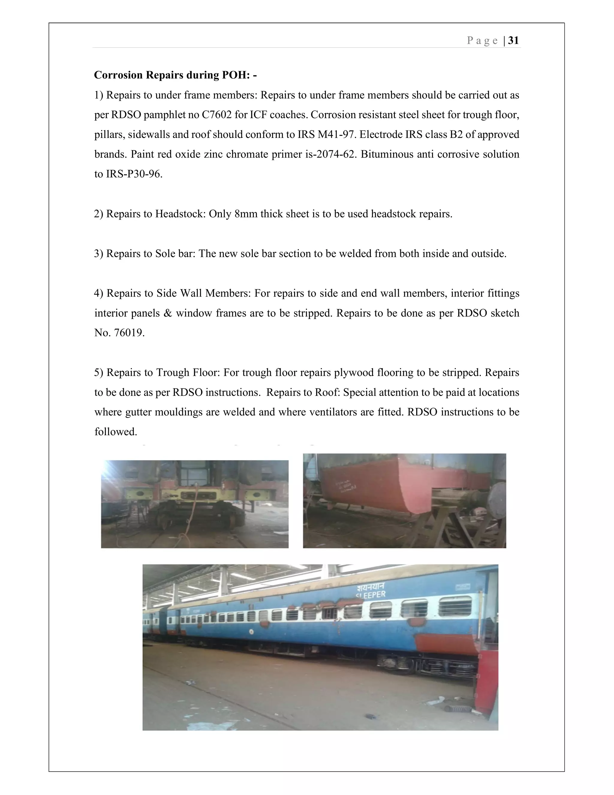
SUMMER TRAINING REPORT
FIFTEEN DAYS INDUSTRIAL TRAINING
AT
WESTERN RAILWAY CARRIAGE REPAIR
LOWER PAREL WORKSHOP
(A Unit of INDIAN RAILWAY)
COLLEGE NAME
WALCHAND INSTITUTE OF TECHNOLOGY, SOLAPUR
SUBMITTED BY: SUBMITTED TO:
CHIRAG JAIN BTC
P a g e | 2
ACKNOWLEDGEMENT
We would like to thank the entire Workshop, Lower parel. Who has provided us this
sessional training. We are thankful to the BTC (Basic Training Centre), who organized our
training schedule and also for their benevolent guidance and kind cooperation throughout our
training along with completing this project report and provided us the various knowledge about
their workshop.
We also thanks to the workers of their respective stations, who were always ready to
clarify our doubts and helped us to increase our knowledge by illustrating us to the finer points.
We wish to express our deep gratitude to all the concerned persons, whose eagerness
and co-ordination have given us the success to complete our training in the organization.
We hope that our report will reflect our technical knowledge and innovativeness, which we
gained at Western Railway Carriage Repair Workshop Lower parel.
P a g e | 3
DECLARATION
This report is based on the summer training we have undergone in the premises of Western
Railway Carriage Repair Workshop Lower parel (WRCRW) A unit of INDIAN RAILWAY
from 8rd
June 2019 to 22th
June 2019. We obtained the knowledge of Carriage Repair through
various workshops arranged to us by the Railway administration. The experience of the training
was good and we learned lots of things. We were successfully able to complete the training.
PLACE:- Lower Parel
DATE:-
P a g e | 4
PREFACE
Industrial Training is meant to expose the students of engineering of the actual Industrial
Processes about which they have mean studying in detail from their semesters. They have spent
the last two years in gaining theoretical knowledge of various manufacturing and assembly
processes.
The fifteen days training has exposed us to the actual application of the various studied. The
training period has been very interesting wherein we got to know how the final product comes
to the market. Each product undergoes a number of qualities control test to bring in uniformity
and quality.
Each field requires skilfully handling and training at given at each step which will help us in
the long run.
P a g e | 5
SHOP SCHEDULE
Shop Particular Date
BUF 1 Lifting, lowering and maintenance of ICF Bogie 8-06-19
FIAT (LHB) Lifting, lowering and maintenance of FIAT Bogie of LHB
coaches
10 & 11-6-19
FTG II Maintenance of suspension springs & Shock absorber
12 & 13-6-19FTG 1 Maintenance of Bogie components
INSP II Inspection of Bogie and bogie components
AB (DV) Maintenance of Air brake system & DV
14 & 15-6-19
AB (NTL) Single car testing
WHS Maintenance of wheels & axle
17 & 18-6-19
RB Maintenance of Roller Bearing and CTRB
INSP III Inspection od wheel, axle & bearing
CR III Corrosion repair of coach body, Head stock and sole bar
repair fitting section
19-6-19
ACC Furnishing of AC coaches 20-6-19
PAINT Painting of Rly coaches
21-6-19
TRIM Upholstery processing & PVC laying practice
INSP I & V Pre & Final inspection of coaches
22-6-19
BUF II Final inspection of bogie
ISO ISO 9001;14000;18000
BTC Report submission and relieving
P a g e | 6
ORGANIZATION INTRODUCTION
Carriage Repair Workshop based at Lower Parel in the city of Mumbai, India is a premier
Broad-gauge coaching workshop of Western Railway, India. The workshop undertakes the
periodic overhauling of passenger main line coaches. It also manufactures wheel sets for the
workshop as well as various Locomotives in Mumbai.
The workshop is spread over an area of around 14 Hectares in the heart of the city of Mumbai.
The workshop was originally a Locomotive repair workshop during the British period and came
up between the year 1870-76. The workshop was set up by the erstwhile BB&CI (Bombay
Baroda and Central India Railway).
 MAIN ACTIVITY:
The workshop undertakes the periodic overhauling of two main types of coaches. The first
category of the coach is known as the ICF design coaches. The second category of the coach
is the LHB design coaches.
In a year, 1500 coaches are POHed at Lower Parel Workshop. They include the General Class
coaches, Sleeper class, Three tier, Two tier and the First-class Air-Conditioned coaches. It also
undertakes the POH of Milk Tankers of the NDDB (National Dairy Development Board). The
average outturn of the coaches has increased from 1,463 in the year 1990 to 1,530 in the year
2008. Out of 1,530 coaches, 330 coaches are air-conditioned coaches. The air-conditioned
coach outturn has increased from 192 in the year 1990 to 330 in the year 2008. The average
POH cycle for the coach is 25 days.
It also manufactures wheel sets for the workshop divisions as well as the EMU workshop at
Mahalaxmi. The average supply of wheel sets is 12000-wheel sets per year out of which 120-
wheel sets are sent to the divisions and another 120-wheel sets to EMU workshop.
P a g e | 7
(BUF 1) LIFTING LOWERING AND MAINTENANCE OF ICF BOGIE
 In order to increase the life of bogie and for proper functioning of bogie, regular
maintenance of bogie should be done.
 The following are the steps involved in bogie maintenance:
1. Coach Lifting.
2. Bogie cleaning.
3. Bogie dismantling.
4. Component cleaning.
5. Attention to components.
6. Repair of component.
7. Bogie assembly.
8. Load testing and adjustment.
9. Lowering of coach.
10. Final adjustment.
 In washing plant, first the oil from the side bearer oil bath is removed.
 Bogie is washed with high pressure hot water jet to remove all dust, mud, scales, grease
without damaging the base primer coating. After washing and drying, bogies are rolled to
dismantling line.
P a g e | 8
 Make sure that the vent screws are opened. Lift the bogie frame along with the bolster using
overhead crane till the eight axle guides disengage from the lower spring seats.
 Lower the bogie frame and the bolster on to the shop floor.
 Remove and collect the axle box guide components and helical springs and send to
washing plant for thorough cleaning.
 Wheel sets must be first cleaned thoroughly in the washing plant and then sent to the wheel
shop.
 Remove vertical shock absorbers and send to the maintenance section.
 Dismantle bolster suspension hangers by using a jack. Lift the bolster off the bolster springs
and remove the bolster springs.
 Send the bogie frame, bolsters and lower spring beam to washing plant for thorough
cleaning.
 Transport the cleaned and dried bogie frame, bolster to inspection and repair stands.
 Place the wearing plate and wearing piece in side bearer oil bath. Fill the oil bath with 2
liters of oil.
 Apply graphite grease on centre pivot pin and lower the coach body on side bearer pieces.
Care should be exercised to make sure that the side bearers are resting properly.
 Defects in bogie assembly:
 Bolster for twist, crack, corrosion etc.
 Rubber sealing cap of centre pivot, if torn or damaged.
 Bolster suspension straps if bent or damaged.
 Check verticality of pivot.
 Clearance between bolster and bogie frame is 57 mm.
 Spring having cracks, dents should be rejected.
 Inspection of brake beams is important for corrosion, cracks.
 Wheel shifted on axle.
 Heat cracks on wheel.
 Rectifications of bogie assembly defects:
 Check the bogie thoroughly for any possible cracks.
 Check the axle guides and other welding joints of the bogie frame.
 Axle guide alignment should be checked with the help of gauges.
 Bronze wearing piece for side bearer, should not worn put more than 1.5 mm in thickness.
 When the spring is to be replaced it should be ensured that the variation in the height of the
spring with respect of other springs forming either primary or secondary suspensions
already on the bogie should not be more than 6 mm.
 Safety precautions:
 Whenever a coach is examined at maintenance depot, it should be ensured that prescribed
number of various components are fitted at specified location.
 All fasteners like bolts, nuts etc. used in under frame equipments should be checked.
P a g e | 9
Lifting, Lowering and Maintenance of FIAT Bogie of LHB
Coaches
Linke Hofmann Busch (LHB) coaches are the passenger coaches of Indian railways that have
been developed by Linke-Hofmann-Busch of Germany (renamed Alstom LHB Gmbh in 1998
after the takeover by Alstom) and mostly produced by Rail coach factory in Kapurthala,
India. They have been used since 2000 on the broad gauge (1676mm) network of Indian
railways. Initially, 24 air-conditioned coaches were imported from Germany for use in the
Shatabdi Expresses, after which the rail coach factory started manufacturing after technology
transfer.
The coaches are designed for an operating speed up to 160 km/h and could go up to 200
km/h. However, they have been tested up to 180 km/h.
First LHB coach was manufactured in RCF (Railway Coach Factory), Kapurthala.
Coach Manufacturing Factories are:
1. Rail Coach Factory (RCF), Kapurthala, Punjab
2. Morden Coach Factory (MCF), Raebareli, Uttar Pradesh
3. Integral Coach Factory (ICF), Perambur, Chennai
The LHB coach whose maintenance is to be done as per required for example: -
 SS1: 18 months/ 6 lakh kilometres
 SS2: 3 years/ 12 lakh kilometres
 SS1.2: 4 years 6 months/ 18 lakh kilometres
 SS3: 6 years/ 24 lakh kilometres
Get lifted in night shift and all the parts were sent to their respective maintenance department.
First of all, the pre-inspection of coach has been done and then the report of inspection
prepared. After the report preparation all the maintenance procedure were carried out.
If the coach came for its SS3 maintenance all the parts of coach and bogie from smallest part
to the largest part first checked if they are usable, they are being used and if not, they get
replaced.
Main parts of LHB (FIAT) Bogie are as follows: -
1. Primary suspension
2. Secondary suspension
3. Brake assembly
4. Bolster assembly
5. Coupling assembly
Primary suspension:
1. Bogie frame
2. Rubber disks
3. Centring disk
4. Internal spring
5. External spring
P a g e | 10
6. Bump stop
7. Shim
8. Centring disk
9. Control Arm Lower Part
10. Plate
11. Block
12. Rubber joint
13. Control Arm Upper Part
14. Damper
Secondary suspension:
1. Bolster beam
2. Anti- roll bar
3. Internal spring
4. External spring
5. Centring disk
6. Bogie frame
7. Vertical damper
8. Lateral damper
9. Safety cables
10. Traction rod
11. Yaw damper
Brake assembly consist of:
 Brake calliper
 Brake disc
 Brake cylinder
P a g e | 11
Coupling assembly:
LHB coaches comes with CBC coupling i.e. Centre Buffer Coupling which is much safer and
effective then screw coupling draft gear, shank, supporting device, rear and front plate, knuckle
thrower, knuckle pivot pin, knuckle supporting pin, etc.
Shock absorbance system: -
 Yaw damper : 04
 Primary damper : 08
 Lateral damper : 02
 Vertical damper : 04
P a g e | 12
FITTING-I
Today we were allotted the FTG 1 workshop. We firstly visited the SSE of the workshop and
ask him about the details of the workshop. We were provided with a guide and firstly we
observed the gas cutting operation being done on metal sheet. The gas cutting machine contains
acetylene gas with a feed pipe to control the amount of gas released through the pipe. We
observed the making of different components using gas welding. After this we observed the
plate bending process. The sheets were placed at the bottom and were given the shape according
to the desired requirement. The different components of coach and bogie were refurbished and
made in this workshop.
P a g e | 13
FTG II: Maintenance of suspension springs & Shock absorber
On 12 June, we have allotted in FTG II shop where maintenance of Suspension and Shock
absorber are checked by dissembling the whole body up to washer.
Suspension are used in ICF and Shock absorber used in LHB.
ICF Bogie having two types suspension, primary and secondary
Primary Suspension: -
 Dashpot arrangement which is a cylinder and piston like arrangement.
 Lower spring seat act as a cylinder which contain viscous oil.
 Axle guide act as a piston which having a guide cap at bottom with perforations.
 Oil enter through the perforations of the axle guide and release slowly which damp
the oscillations during running of the train.
Secondary suspension: -
 The secondary suspension arrangement of the ICF bogies is through bolster springs.
The bogie bolster is not bolted or welded anywhere to the bogie frame. It is attached
to the bogie frame through the anchor link.
 Weight of the coach is transferred through side bearers on the bogie bolsters. The
ends of the bogie bolsters rest on the bolster helical springs placed over the lower
spring beam suspended from the bogie frame.
Shock Absorber in LHB There are 4 types damper we have seen in the shop. They are as
follows: -
1. Primary Vertical Dampers
2. Secondary Vertical Damper
3. Secondary Lateral Damper
4. Yaw Damper
P a g e | 14
During Maintenance they check following things: -
 Deformations Damage
 cracks
 and oil leaks
 Aging
 Visually, Testing during
 vibration.
If above things were found then shock absorber is dissembled and maintenance has been done
by changing components
P a g e | 15
Maintenance of Air Brake system and Distributor Valve: -
On 14 June, we have allotted in Air Brake and DV shop where maintenance of different
components of air brake system and Distributor Valve by dissembling the whole system
Components: -
 Common pipe bracket (CPB)
 Distributor valve (DV)
 reservoir (CR)
 Auxiliary reservoir (AR)
 Brake cylinder (BC)
 Brake pipe & feed pipe
 Air hose with palm end
 coupling
 Cut off angle cock
 Dirt collector
 Isolating cock (2-way and 3-way)
 Check valve with choke
 Brake riggings
P a g e | 16
Working of Air Brake: -
Three Working Stages
 Charging stage
 Brake pipe (BP) charged with 5 Kg/cm2 air pressure.
 Application stage BP pressure dropped for brake application.
 Releasing stage
BP pressure again raised for brake release
DISTRIBUTOR VALVE: -
Three designs of DV’s are in use on Indian Railway
1. KE type.
2. C3W Type.
3. P4aG type.
FUNCTION: -
 System to regime pressure.
 During normal/running condition.
 Helps in all types of brake application.
 Graduated, full service as well as emergency type.
 Helps in brake release.
 Graduated as well as manual.
 Controls the brake application & release time.
 As per service conditions.
 Limits max. designed BC pressure.
 Accelerates propagation of initial reduction of
 BP pressure throughout the length of the train
 By arranging local vent of BP pressure inside the DV
 till BC pressure maintained at 0.8 Kg/cm2
 Protects overcharging of CR up to some extent
 When the BP is overcharged after full-service application for quick brake release.
 Facilitates to isolate the system if required, and
 Complete system can be evacuated manually.
P a g e | 17
AIR BRAKE PROCESS
During Maintenance, all braking components dissemble and check all the minor component
where it is proper or not?? It there is rough surface, defects then either it goes for grinding or
replacing with new components. It has been checked that leakage of air should not happened
when pressure is applied by applying particular type of fluid. DV testing is performed to check
whether it is performed as per desire.
P a g e | 18
SINGLE CAR TESTING (NTL)
Single car testing is performed on coach to ensure proper functioning of air brake system in a
coach. It is generally performed on the sick coach that is attended on the sick line or on the
coaches undergone ‘C’ schedule.
Whenever a sub assembly of the air brake system is replaced either in depot or workshop, the
coach must be checked for the proper performance of the air brake system by conducting
Single Car Test. This test is also carried out after periodic overhauling and after change of
DV in the workshop.
Following Air Brake Testing functions are carried on NTL, old lifting & new lifting:
 Overall leakage test
 ICV operations- inter communication valve
 AR, CR charging
 DV leakage testing
 DV functional testing on coach
 Brake cylinder operations- Application & release test
 Continuity testing on coach
 Sensitivity and insensitivity test
 Graduated application & release test
 Guard’s emergency valve test
 Passenger emergency valve test
P a g e | 19
Wheel & Axle Maintenance
 Wheel & Axle Assembly
Fig: - ICF Coach wheel
P a g e | 20
Fig:- LHB Coach wheel
Railway Wheels
The wheel is better understood by dividing it into the following parts
1. Hub
2. Disc
3. Tyre
Fig: - Different sections of wheel
1. Hub is the center portion of the wheel, where the wheel is fixed to the axleby means of
interference fit.
Thickness of the wheel is maximum atthe hub portion
2. Disc is the portion of the wheelbetween the hub and the tyre.
P a g e | 21
This portion is the thinnest portion of the wheel as it does not come in contactwith rail
nor it is coming in contact with the axle.
3. Tyre is the portion in contact with the rail, which wears out in service.
The profile of the tyres is significant for safe running of the trains.
WheelDefects
1. Manufacturing Defects
2. Improper AssemblyPractices
3. Normal Wearand Tearduring service
1. Manufacturing Defects
 CastingDefects
 Improper Heattreatment
 Machining Imperfections
2. Improper Assembly Practices
 Stipulated dimensional tolerances for Wheel seat and bore not adhered to
resulting in use of higheror lower than the prescribed force during pressing
leading to improper wheel set assembly.
 Ovalityon Journals- 0.02 mm (max)
 Taper on Journal - 0.01mm(max)
 Differencein dia of wheels on the same axle should not exceed 0.5mm
3. Measurable wheel defects arising dueto normal wear & tear during service
 Thin flange
 Deep flange
 Sharp flange
 Less radius at root of flange
 Hollow tyre
 Thintyre
 Flattyre
P a g e | 22
4. Other Wheel defect
A. Shelledtread: -
Shelling can be identified by pieces of metal breaking out of the tread surface in
several places more or less continuously around the rim. Shelling takes place when
small pieces of metal break out between the fine thermal checks. These are generally
associated with small skid marks or “chain sliding”
Fig: -shelled tread
B. Shatteredrim: -
A wheel with a fracture on the tread or flange must be withdrawn from service
Fig: - Shatteredrim
P a g e | 23
C. Spreadrim: -
Spreading of the rim is usually accompanied by a flattening of the tread, which may
or may not have cracks or shelling on the tread.
Fig: - Spreadrim
D. Thermalcrack: -
Thermal cracks appear on a wheel treaddue to intense heating of the wheel
arising out of severe brake binding. Such cracks occur on the tread and
generally progress across the tread in a transverse & radialdirection.
Fig: - Thermalcrack
E. Disccrack: -
A crack on the disc due to material failure is called disc crack. The wheel should be
withdrawn from service.
Fig: - Disccrack
P a g e | 24
F. Looseaxle: -
While assembling wheel with axle proper interference should be maintained
between wheel and axle. Due to improper selection of interference the wheel
may shift outwards or it may come out completely. Loose axle is a rejectable
defect.
Axles involved in Accidents should be magnaflux tested in addition to
Ultrasonic test.
Axle having notch should be withdrawnfrom service.
Wheel Lathe
 Requirement of Wheel Replacement
1. Existing tread dia ≤ last shop issue size
2. Shattered Rim-a fracture on the tread/ flange
3. Spread Rim-widens out on the front face.
4. Shelled Tread-metal piece breaking on tread.
5. Thermal Cracks-appears on tread.


P a g e | 25
Stamping of particulars
Different types of Axles
Roller and Bearings
 SPHERICAL ROLLER BEARING
 BEARING COMPONENTS
P a g e | 26
1. Outer ring
Outer ring for spherical roller bearings are manufactured from forged and rolled rings
from bearing quality steel. It is through hardened and precision ground all over. The
track or roller surface of bearing outer ring is spherical in shape for self-aligning.
2. Inner Ring
Inner ring for spherical roller bearing are also made from bearing quality steel which
is forged and rolled. Inner rings are also precision machined heat- treated and
precision ground. Inner rings have two rolling surface which are ground together with
high accuracy.
3. Roller
Roller are either forged or machined from bearing quality steel bars & then through
hardened and ground to high degree of accuracies.
4. Cage
Spherical roller bearings are fitted with machined brass cages. These cages are made
from brass centrifugal castings and then precision machined. Brass cages have
advantage of assuring positive lubrication and cooler running of the bearing therefore
are best recommended for railway applications.
STORAGE AND HANDLING OF BEARINGS
Spherical roller bearings are coated with rust preventive oil prior to packing. Therefore,
bearings must be stored in original packing. Following are some of instructions to be
exercised during storage and handling of the bearing.
1. Bearing storage: -
 The bearing should be stored in a clean and dry place and should be protected
from heat, dust, moisture, direct sunlight, vibrations etc. Even microscopically
small dirt may start bearing damage and prematurefailure.
 Store bearing in original packing on clean and dry racks away from wall and
floor.
 Do not store any chemical / solvent in the bearing storage area, which that can
cause corrosion due to chemical attack.
 Use older stock first.
2. Handling and transportation: -
P a g e | 27
 Spherical Roller Bearings are properly packed in pallets before supply to
customers. During transportation following precautions are necessary.
 Do not throw or drop the packed boxes while loading & unloading in the
lorry/truck or any transportation vehicles.
 Use fork lift truck or crane for loading & unloadingpurpose.
 When using cranes, use proper slings to avoid any damage to the packing.
 As far as possible same size of the packed boxes should be stacked one over
other.
 Do not transport any boxes containing oil, liquid, chemicals etc. in same
transportation vehicle.
 Do not keep heavy iron articles on the pallets to avoid any damage to packing.
 Cover packed boxes with tarpaulin to protect from dust, rain, water etc.
ROLLER BEARING MAINTENANCE IN WORK SHOP
Roller Bearing Maintenance Shop should be well equipped with all the tools, equipments
and facilities for careful bearing handling. It should have proper workflow for easy
maintenance of roller bearings. Clean surroundings and dust free atmosphere should be
maintained in the shop. It should have adequate equipment and facilities for cleaning,
handling, dismounting/mounting, inspection, repair and storage of roller bearings.
Roller bearings are required to be inspected periodically at a pre-defined schedule in the
workshops in a Roller Bearing Maintenance Shop well equipped with all the facilities
and proper lay out.
A. Periodicity of Inspection of Roller Bearing
i. All roller bearings should be cleaned, inspected and re-lubricated with fresh
grease during each attention to the wheel set /bearings in the workshop.
ii. The roller bearings should be dismounted from the wheel set during every
alternate attention in the workshops for thorough inspection of the components,
rear cover and renewal of the felt sealing ring. The wheel bearing should however
necessarily be dismounted and overhauled in case of any warranted out of course
of attention in the workshop.
Inspection of the Spherical Roller Bearing during POH in the
Workshops
 Spherical roller bearing should be dismantled in the workshops after every 18 months
periodicity (i.e. during POH) and following procedures should be followed for carrying
out inspection and rejection in case of defects observed:
 Clean the exterior of axle box, front cover, axle box housing.
 Remove axle box with the help of mechanical screw type puller, by taking care to protect
axle center with the use of pad not allowing the screw to rest on the axle centre. The end
locking plate should be removed.
P a g e | 28
 Remove old grease. Roller bearing and its components should be thoroughly washed and
cleaned.
 All components viz., rollers, cage, outer and inner rings (races), roller track of outer ring
should be examined after swiveling the outer ring.
 Zyglo testing should be ensure as per instructions
Dismounting of Bearing with Hydraulic Press
 The bearing assembly should be removed with a hydraulic extractor.
 Normally 12 -15 tonne pressure is required but in some cases 30 to 40 tonnes
pressure may also be required to break the bearing fit.
 When bearings are removed from the axle, a pilot sleeve should be fastened to the end
of the axle or to the press ram to keep the bearing parts together and protect them
from damage.
Pressing of Bearing Assembly on Axle
 Place the wheel and axle assembly in a bearing press, in position to press the bearing
assembly on to the axle.
 Measure and record the outer Dia of axle at three locations. Each location should have
three readings at 1200C. Refer drawing for axle dimensions.
 Fit the pilot sleeve onto the end of the axle, using the screws to hold it in position. Slide
the bearing assembly over the pilot as far as it will go and place the bearing assembly.
 Coat the bearing seats of the axle with Oil (SAE 30)
 Apply pressure to the end of the assembly sleeve until the bearing assembly is correctly
seated. Keep rotating the CTBU by using both hands while mounting it on the axle. If it
stops rotating then mounting should be stopped. After removing the CTBU from the axle
it should be sent for refurbishment.
 To ensure that the bearing is firmly seated against the axle fillet, the pressure indicated
on, the gauge during pressing on should be increased by 50%. This seating load pressure
should be within the limits 20-30 tonnes.
P a g e | 29
CARTIRIDGE TAPERED ROLLER BEARING
P a g e | 30
CR III
Corrosion Repair of Coach body, Headstock and Sole bar Repair-Fitting
Section
Rust is the result of oxidation of metal. Any prolonged contact of water and salts leads to
corrosion of the metal. Any metal which contains iron bonds with oxygen found in water
molecule and forms iron oxide or rust. Rust will speed up the corrosion process so proper
upkeep is required.
Corrosion is a chemical phenomenon of oxidation of iron which results in loss of section and
therefore of strength. Oxidation takes place only when steel is in contact with atmosphere in
presence of moisture. So, in order to stop corrosion, we have to prevent the contact of
atmosphere with the steel. In order to do so the coaches are painted by inhibitive zinc
chromate red oxide primer.
Vulnerable members and location: -
1. Headstock
2. Tubular frame below lavatories and trough floors in all coaches adjoining lavatories and
under luggage compartments of SLR and parcel van as well as pantry vehicle.
3. Sole bars, turn under and body pillars.
4. Sole bars and pillars behind the sliding door pockets of SLR and parcel vans
5. Sole bars, pillars and turn under at door corner.
Above fig shows the damaged part of the area near headstock
P a g e | 31
Corrosion Repairs during POH: -
1) Repairs to under frame members: Repairs to under frame members should be carried out as
per RDSO pamphlet no C7602 for ICF coaches. Corrosion resistant steel sheet for trough floor,
pillars, sidewalls and roof should conform to IRS M41-97. Electrode IRS class B2 of approved
brands. Paint red oxide zinc chromate primer is-2074-62. Bituminous anti corrosive solution
to IRS-P30-96.
2) Repairs to Headstock: Only 8mm thick sheet is to be used headstock repairs.
3) Repairs to Sole bar: The new sole bar section to be welded from both inside and outside.
4) Repairs to Side Wall Members: For repairs to side and end wall members, interior fittings
interior panels & window frames are to be stripped. Repairs to be done as per RDSO sketch
No. 76019.
5) Repairs to Trough Floor: For trough floor repairs plywood flooring to be stripped. Repairs
to be done as per RDSO instructions. Repairs to Roof: Special attention to be paid at locations
where gutter mouldings are welded and where ventilators are fitted. RDSO instructions to be
followed.
P a g e | 32
ACC
It is the process of furnishing AC coaches where coaches are brought first to furnishing
department. In this department all the basic and luxury equipments are checked consequently
actions like repair or replacement of various parts are done.
The different supervisors are allotted for different inspection of these parts. The parts that can
be kept under construction are as follows:
1. Furnishing items
2. Fire and safety issues
3. Toilet system and bio-toilet introduction
4. Plumbing system
5. Water tank
6. Round concerned seats and berths in carriage
7. Chairs in chair car coaches
8. Reclining arrangement in chairs
OTHER PASSENGER AMENITY ITEMS:
1. Overhead luggage racks
2. Mirrors in compartments and toilets
3. SS D type wash basins
4. Soap tray and liquid tray dispensers
5. Towel rings
6. 110 volts mobile/laptop charger
7. CFL and air circulating DC ceiling fans
8. Roof ventilator
9. Body Slide Door (BSD)
P a g e | 33
PAINTING OF RAILWAY COACHES
On June 21, 2019, we were allotted the paint workshop. In the workshop SSE told us to explore
the shop. While exploring we saw a lot of coaches standing ready for painting. The workers
there were washing the coaches to remove the dust and dirt. We went to the SSE for getting
the details about the workshop. We asked him about the main reason behind painting the
coaches on which he answered by saying that they do it to prevent coaches from corrosion, to
protect it from wear and tear, to reflect light and heat and to give it an aesthetic look. He also
told us about the composition of the paint which were pigment, solvent, binder,etc. He then
told us about the schedule of painting and the process too. There are two types of schedules
namely:
‘A’ Schedule
‘B’ schedule
‘A’ Schedule
Day-1: Remove old paint.
Day-2: One coating of Red Oxide Zinc Chromate Primer.
Day-3: One coating of Brush Filler followed by spot putty to fill up holes/dents.
Day-4: Second coating filler.
Day-5: Rubbing down with Silicon Carbide Water proof paper. (Gr. 120 and 220)
Day-6: One coating of under coat.
Day-7: Flatting with Silicon Carbide water proof paper (Gr. 300). Another coating of enamel
finishing.
Day-8: Flatting with Silicon Carbide water proof paper (Gr. 400). Another coating of enamel
finishing.
Day-9: Lettering with Golden, Yellow and Miscellaneous work. (Cleaning window glasses,
etc.)
‘C’ Schedule
Day-1: Cleaning with soap solution or any other solution and wash thoroughly with water.
Day-2: Spot putty if necessary, give one coat of undercoat.
Day-3: : Flatting with Silicon Carbide water proof paper (Gr. 120and 220). Another coating of
enamel finishing.
Day-4: Same as Day-3. (Gr. 400)
P a g e | 34
Day-5: Lettering with Golden and Miscellaneous Work.
Our SSE told us that ‘A’ Schedule is a period of 9 days and ‘C’ Schedule of 5 days.
The workers use different grades of sand paper to make the surface smooth.
We then went to one of the workers there to ask about how they lettering and numbering on
the coaches on which he shown us a frame on which the numbers were printed and they used
some ink and then they aligned the frame on the marked place and pressed it against it against
the coach body. Using a flat piece, he printed the number on the coach. The workers washed
the coach with the mixture of bleaching powder.
Each coach was marked with the coach number, code and name of base station for primary
maintenance. And its return date showing the month and year in which the coach is required to
be returned to the owning.
We then ended up by taking the signature of the SSE.
Upholstery Process and PVC Laying Practice
On 21th
June 2019, we had to go the workshop where the upholstery process and PVC laying
practice were performed. We reported to the SSE and took the brief idea about the workshop.
This workshop covered a good amount of area and was one of the most important workshop
in focusing on passenger comfort. This was all about the luxurious amenities that a passenger
gets to experience while travelling. We then visited to a woman who was removing the foam
and seat cover. The workshop divided the work in smaller sections. Each worker was
assigned with some particular work to achieve excellent result.
We then visited a worker who was doing some cutting work. We asked him about the main
objective of the workshop on which he informed us that they focused on passenger comfort
and luxury. He gave us some information about how they select the colour of the seat cover
based on the type of coach. Blue rexin cover is selected for all ICF NON-AC coaches and all
LHB coaches. Whereas the brown rexine is selected for all AC ICF coaches.
The worker told us about the duration of seat cover. The brown colour cover and the blue
colour cover has three-year warranty. The material of the cover is fireproof. The adhesive
used to stick the foam is called ‘Royal Bond’. Then we visited a worker whose work was to
calibrate the dimensions of the seat. He gave us the knowledge on importance of proper
dimensioning of the seat. He told us seats of 2nd
Ac has a dimension of 5-foot 10 inch which
is same for both upper and lower berths. For 3rd
AC coach the lower berth has a dimension of
around 6-foot and the dimension is same for upper berth as of 2nd
AC coach. The dimension
P a g e | 35
of seat for 1st
AC is not fixed. The thickness varies from 2.5 to 3 inches for AC coaches and
for 2-inches NON-AC coaches.
Then we visited the flooring section where a worker was sticking the PVC’S together. He
told us that the blue PVC is used for ICF Non-AC and LHB coaches, whereas brown PVC
was used for all ICF coaches. There were some women who were doing the stitching work of
seat cover. The SSE showed us a seat which was around 9 to 10 years old. He dismantled is
by pulling out the seat cover and we saw the condition of the foam inside which was really
bad. They then cleared off the whole foam and sent it to the next worker for inspection.
ISO 9001, 14000, 18000
ISO 9001:
ISO 9001 is an international standard that gives the requirements for an organization for quality
management system (QMS). It is a part or family of standard published by international
organization for standardization (ISO).
ISO 14000:
ISO 14000 is primarily concerned with ‘Environmental Management’. Environmental
management systems (EMS) such as ISO 1400, provide a framework for organization that wish
to effectively manage their environmental affairs. The efficient and effective management of
process of ISO14000 is going to affect whether or not everything has been done to ensure a
product will have the least harmful impart on the environment, at any stage in its life cycle
either by pollution, or by depleting natural resources.
ISO 18000:
ISO 18000 is an international standard that describes a series of diverse RFLD technologies,
each using a unique frequency range. ISO/ IEC 18000 consist of the following parts under the
general title information technology- radio frequency identification for item management.
Management system requires:
 Quality management system and their application throughout the organization.
 The sequence and interaction of these process.
 Criteria and method needed to ensure that both the operation and control of these
processes are effective.
P a g e | 36
CONCLUSION
It has been a great privilege to be able to work and train in the Carriage Repair Workshop,
Lower parel of Western Railway. This training has been a great learning experience and one
which will prove to be immensely useful in the future.
This was our first practical experience of an industry or workshop of any kind and we are happy
that we could learn a lot in this short span.
We understood the various processes involved in the POH of Carriages, the various workshops,
sections, etc.
We realized the importance of the work that is being done here as it is directly related in some
or the other way to the safety of passengers, hence it needs to be done responsibly.
We got knowledge of the hierarchy of the Railway Administration.
Thus, this training will certainly benefit us in our future career journey as experience in any
actual industry is always helpful. It also taught us the importance of team work as was shown
by the workers in different sections

Summer Internship/Training report at Indian Railway

  • 1.
    SUMMER TRAINING REPORT FIFTEENDAYS INDUSTRIAL TRAINING AT WESTERN RAILWAY CARRIAGE REPAIR LOWER PAREL WORKSHOP (A Unit of INDIAN RAILWAY) COLLEGE NAME WALCHAND INSTITUTE OF TECHNOLOGY, SOLAPUR SUBMITTED BY: SUBMITTED TO: CHIRAG JAIN BTC
  • 2.
    P a ge | 2 ACKNOWLEDGEMENT We would like to thank the entire Workshop, Lower parel. Who has provided us this sessional training. We are thankful to the BTC (Basic Training Centre), who organized our training schedule and also for their benevolent guidance and kind cooperation throughout our training along with completing this project report and provided us the various knowledge about their workshop. We also thanks to the workers of their respective stations, who were always ready to clarify our doubts and helped us to increase our knowledge by illustrating us to the finer points. We wish to express our deep gratitude to all the concerned persons, whose eagerness and co-ordination have given us the success to complete our training in the organization. We hope that our report will reflect our technical knowledge and innovativeness, which we gained at Western Railway Carriage Repair Workshop Lower parel.
  • 3.
    P a ge | 3 DECLARATION This report is based on the summer training we have undergone in the premises of Western Railway Carriage Repair Workshop Lower parel (WRCRW) A unit of INDIAN RAILWAY from 8rd June 2019 to 22th June 2019. We obtained the knowledge of Carriage Repair through various workshops arranged to us by the Railway administration. The experience of the training was good and we learned lots of things. We were successfully able to complete the training. PLACE:- Lower Parel DATE:-
  • 4.
    P a ge | 4 PREFACE Industrial Training is meant to expose the students of engineering of the actual Industrial Processes about which they have mean studying in detail from their semesters. They have spent the last two years in gaining theoretical knowledge of various manufacturing and assembly processes. The fifteen days training has exposed us to the actual application of the various studied. The training period has been very interesting wherein we got to know how the final product comes to the market. Each product undergoes a number of qualities control test to bring in uniformity and quality. Each field requires skilfully handling and training at given at each step which will help us in the long run.
  • 5.
    P a ge | 5 SHOP SCHEDULE Shop Particular Date BUF 1 Lifting, lowering and maintenance of ICF Bogie 8-06-19 FIAT (LHB) Lifting, lowering and maintenance of FIAT Bogie of LHB coaches 10 & 11-6-19 FTG II Maintenance of suspension springs & Shock absorber 12 & 13-6-19FTG 1 Maintenance of Bogie components INSP II Inspection of Bogie and bogie components AB (DV) Maintenance of Air brake system & DV 14 & 15-6-19 AB (NTL) Single car testing WHS Maintenance of wheels & axle 17 & 18-6-19 RB Maintenance of Roller Bearing and CTRB INSP III Inspection od wheel, axle & bearing CR III Corrosion repair of coach body, Head stock and sole bar repair fitting section 19-6-19 ACC Furnishing of AC coaches 20-6-19 PAINT Painting of Rly coaches 21-6-19 TRIM Upholstery processing & PVC laying practice INSP I & V Pre & Final inspection of coaches 22-6-19 BUF II Final inspection of bogie ISO ISO 9001;14000;18000 BTC Report submission and relieving
  • 6.
    P a ge | 6 ORGANIZATION INTRODUCTION Carriage Repair Workshop based at Lower Parel in the city of Mumbai, India is a premier Broad-gauge coaching workshop of Western Railway, India. The workshop undertakes the periodic overhauling of passenger main line coaches. It also manufactures wheel sets for the workshop as well as various Locomotives in Mumbai. The workshop is spread over an area of around 14 Hectares in the heart of the city of Mumbai. The workshop was originally a Locomotive repair workshop during the British period and came up between the year 1870-76. The workshop was set up by the erstwhile BB&CI (Bombay Baroda and Central India Railway).  MAIN ACTIVITY: The workshop undertakes the periodic overhauling of two main types of coaches. The first category of the coach is known as the ICF design coaches. The second category of the coach is the LHB design coaches. In a year, 1500 coaches are POHed at Lower Parel Workshop. They include the General Class coaches, Sleeper class, Three tier, Two tier and the First-class Air-Conditioned coaches. It also undertakes the POH of Milk Tankers of the NDDB (National Dairy Development Board). The average outturn of the coaches has increased from 1,463 in the year 1990 to 1,530 in the year 2008. Out of 1,530 coaches, 330 coaches are air-conditioned coaches. The air-conditioned coach outturn has increased from 192 in the year 1990 to 330 in the year 2008. The average POH cycle for the coach is 25 days. It also manufactures wheel sets for the workshop divisions as well as the EMU workshop at Mahalaxmi. The average supply of wheel sets is 12000-wheel sets per year out of which 120- wheel sets are sent to the divisions and another 120-wheel sets to EMU workshop.
  • 7.
    P a ge | 7 (BUF 1) LIFTING LOWERING AND MAINTENANCE OF ICF BOGIE  In order to increase the life of bogie and for proper functioning of bogie, regular maintenance of bogie should be done.  The following are the steps involved in bogie maintenance: 1. Coach Lifting. 2. Bogie cleaning. 3. Bogie dismantling. 4. Component cleaning. 5. Attention to components. 6. Repair of component. 7. Bogie assembly. 8. Load testing and adjustment. 9. Lowering of coach. 10. Final adjustment.  In washing plant, first the oil from the side bearer oil bath is removed.  Bogie is washed with high pressure hot water jet to remove all dust, mud, scales, grease without damaging the base primer coating. After washing and drying, bogies are rolled to dismantling line.
  • 8.
    P a ge | 8  Make sure that the vent screws are opened. Lift the bogie frame along with the bolster using overhead crane till the eight axle guides disengage from the lower spring seats.  Lower the bogie frame and the bolster on to the shop floor.  Remove and collect the axle box guide components and helical springs and send to washing plant for thorough cleaning.  Wheel sets must be first cleaned thoroughly in the washing plant and then sent to the wheel shop.  Remove vertical shock absorbers and send to the maintenance section.  Dismantle bolster suspension hangers by using a jack. Lift the bolster off the bolster springs and remove the bolster springs.  Send the bogie frame, bolsters and lower spring beam to washing plant for thorough cleaning.  Transport the cleaned and dried bogie frame, bolster to inspection and repair stands.  Place the wearing plate and wearing piece in side bearer oil bath. Fill the oil bath with 2 liters of oil.  Apply graphite grease on centre pivot pin and lower the coach body on side bearer pieces. Care should be exercised to make sure that the side bearers are resting properly.  Defects in bogie assembly:  Bolster for twist, crack, corrosion etc.  Rubber sealing cap of centre pivot, if torn or damaged.  Bolster suspension straps if bent or damaged.  Check verticality of pivot.  Clearance between bolster and bogie frame is 57 mm.  Spring having cracks, dents should be rejected.  Inspection of brake beams is important for corrosion, cracks.  Wheel shifted on axle.  Heat cracks on wheel.  Rectifications of bogie assembly defects:  Check the bogie thoroughly for any possible cracks.  Check the axle guides and other welding joints of the bogie frame.  Axle guide alignment should be checked with the help of gauges.  Bronze wearing piece for side bearer, should not worn put more than 1.5 mm in thickness.  When the spring is to be replaced it should be ensured that the variation in the height of the spring with respect of other springs forming either primary or secondary suspensions already on the bogie should not be more than 6 mm.  Safety precautions:  Whenever a coach is examined at maintenance depot, it should be ensured that prescribed number of various components are fitted at specified location.  All fasteners like bolts, nuts etc. used in under frame equipments should be checked.
  • 9.
    P a ge | 9 Lifting, Lowering and Maintenance of FIAT Bogie of LHB Coaches Linke Hofmann Busch (LHB) coaches are the passenger coaches of Indian railways that have been developed by Linke-Hofmann-Busch of Germany (renamed Alstom LHB Gmbh in 1998 after the takeover by Alstom) and mostly produced by Rail coach factory in Kapurthala, India. They have been used since 2000 on the broad gauge (1676mm) network of Indian railways. Initially, 24 air-conditioned coaches were imported from Germany for use in the Shatabdi Expresses, after which the rail coach factory started manufacturing after technology transfer. The coaches are designed for an operating speed up to 160 km/h and could go up to 200 km/h. However, they have been tested up to 180 km/h. First LHB coach was manufactured in RCF (Railway Coach Factory), Kapurthala. Coach Manufacturing Factories are: 1. Rail Coach Factory (RCF), Kapurthala, Punjab 2. Morden Coach Factory (MCF), Raebareli, Uttar Pradesh 3. Integral Coach Factory (ICF), Perambur, Chennai The LHB coach whose maintenance is to be done as per required for example: -  SS1: 18 months/ 6 lakh kilometres  SS2: 3 years/ 12 lakh kilometres  SS1.2: 4 years 6 months/ 18 lakh kilometres  SS3: 6 years/ 24 lakh kilometres Get lifted in night shift and all the parts were sent to their respective maintenance department. First of all, the pre-inspection of coach has been done and then the report of inspection prepared. After the report preparation all the maintenance procedure were carried out. If the coach came for its SS3 maintenance all the parts of coach and bogie from smallest part to the largest part first checked if they are usable, they are being used and if not, they get replaced. Main parts of LHB (FIAT) Bogie are as follows: - 1. Primary suspension 2. Secondary suspension 3. Brake assembly 4. Bolster assembly 5. Coupling assembly Primary suspension: 1. Bogie frame 2. Rubber disks 3. Centring disk 4. Internal spring 5. External spring
  • 10.
    P a ge | 10 6. Bump stop 7. Shim 8. Centring disk 9. Control Arm Lower Part 10. Plate 11. Block 12. Rubber joint 13. Control Arm Upper Part 14. Damper Secondary suspension: 1. Bolster beam 2. Anti- roll bar 3. Internal spring 4. External spring 5. Centring disk 6. Bogie frame 7. Vertical damper 8. Lateral damper 9. Safety cables 10. Traction rod 11. Yaw damper Brake assembly consist of:  Brake calliper  Brake disc  Brake cylinder
  • 11.
    P a ge | 11 Coupling assembly: LHB coaches comes with CBC coupling i.e. Centre Buffer Coupling which is much safer and effective then screw coupling draft gear, shank, supporting device, rear and front plate, knuckle thrower, knuckle pivot pin, knuckle supporting pin, etc. Shock absorbance system: -  Yaw damper : 04  Primary damper : 08  Lateral damper : 02  Vertical damper : 04
  • 12.
    P a ge | 12 FITTING-I Today we were allotted the FTG 1 workshop. We firstly visited the SSE of the workshop and ask him about the details of the workshop. We were provided with a guide and firstly we observed the gas cutting operation being done on metal sheet. The gas cutting machine contains acetylene gas with a feed pipe to control the amount of gas released through the pipe. We observed the making of different components using gas welding. After this we observed the plate bending process. The sheets were placed at the bottom and were given the shape according to the desired requirement. The different components of coach and bogie were refurbished and made in this workshop.
  • 13.
    P a ge | 13 FTG II: Maintenance of suspension springs & Shock absorber On 12 June, we have allotted in FTG II shop where maintenance of Suspension and Shock absorber are checked by dissembling the whole body up to washer. Suspension are used in ICF and Shock absorber used in LHB. ICF Bogie having two types suspension, primary and secondary Primary Suspension: -  Dashpot arrangement which is a cylinder and piston like arrangement.  Lower spring seat act as a cylinder which contain viscous oil.  Axle guide act as a piston which having a guide cap at bottom with perforations.  Oil enter through the perforations of the axle guide and release slowly which damp the oscillations during running of the train. Secondary suspension: -  The secondary suspension arrangement of the ICF bogies is through bolster springs. The bogie bolster is not bolted or welded anywhere to the bogie frame. It is attached to the bogie frame through the anchor link.  Weight of the coach is transferred through side bearers on the bogie bolsters. The ends of the bogie bolsters rest on the bolster helical springs placed over the lower spring beam suspended from the bogie frame. Shock Absorber in LHB There are 4 types damper we have seen in the shop. They are as follows: - 1. Primary Vertical Dampers 2. Secondary Vertical Damper 3. Secondary Lateral Damper 4. Yaw Damper
  • 14.
    P a ge | 14 During Maintenance they check following things: -  Deformations Damage  cracks  and oil leaks  Aging  Visually, Testing during  vibration. If above things were found then shock absorber is dissembled and maintenance has been done by changing components
  • 15.
    P a ge | 15 Maintenance of Air Brake system and Distributor Valve: - On 14 June, we have allotted in Air Brake and DV shop where maintenance of different components of air brake system and Distributor Valve by dissembling the whole system Components: -  Common pipe bracket (CPB)  Distributor valve (DV)  reservoir (CR)  Auxiliary reservoir (AR)  Brake cylinder (BC)  Brake pipe & feed pipe  Air hose with palm end  coupling  Cut off angle cock  Dirt collector  Isolating cock (2-way and 3-way)  Check valve with choke  Brake riggings
  • 16.
    P a ge | 16 Working of Air Brake: - Three Working Stages  Charging stage  Brake pipe (BP) charged with 5 Kg/cm2 air pressure.  Application stage BP pressure dropped for brake application.  Releasing stage BP pressure again raised for brake release DISTRIBUTOR VALVE: - Three designs of DV’s are in use on Indian Railway 1. KE type. 2. C3W Type. 3. P4aG type. FUNCTION: -  System to regime pressure.  During normal/running condition.  Helps in all types of brake application.  Graduated, full service as well as emergency type.  Helps in brake release.  Graduated as well as manual.  Controls the brake application & release time.  As per service conditions.  Limits max. designed BC pressure.  Accelerates propagation of initial reduction of  BP pressure throughout the length of the train  By arranging local vent of BP pressure inside the DV  till BC pressure maintained at 0.8 Kg/cm2  Protects overcharging of CR up to some extent  When the BP is overcharged after full-service application for quick brake release.  Facilitates to isolate the system if required, and  Complete system can be evacuated manually.
  • 17.
    P a ge | 17 AIR BRAKE PROCESS During Maintenance, all braking components dissemble and check all the minor component where it is proper or not?? It there is rough surface, defects then either it goes for grinding or replacing with new components. It has been checked that leakage of air should not happened when pressure is applied by applying particular type of fluid. DV testing is performed to check whether it is performed as per desire.
  • 18.
    P a ge | 18 SINGLE CAR TESTING (NTL) Single car testing is performed on coach to ensure proper functioning of air brake system in a coach. It is generally performed on the sick coach that is attended on the sick line or on the coaches undergone ‘C’ schedule. Whenever a sub assembly of the air brake system is replaced either in depot or workshop, the coach must be checked for the proper performance of the air brake system by conducting Single Car Test. This test is also carried out after periodic overhauling and after change of DV in the workshop. Following Air Brake Testing functions are carried on NTL, old lifting & new lifting:  Overall leakage test  ICV operations- inter communication valve  AR, CR charging  DV leakage testing  DV functional testing on coach  Brake cylinder operations- Application & release test  Continuity testing on coach  Sensitivity and insensitivity test  Graduated application & release test  Guard’s emergency valve test  Passenger emergency valve test
  • 19.
    P a ge | 19 Wheel & Axle Maintenance  Wheel & Axle Assembly Fig: - ICF Coach wheel
  • 20.
    P a ge | 20 Fig:- LHB Coach wheel Railway Wheels The wheel is better understood by dividing it into the following parts 1. Hub 2. Disc 3. Tyre Fig: - Different sections of wheel 1. Hub is the center portion of the wheel, where the wheel is fixed to the axleby means of interference fit. Thickness of the wheel is maximum atthe hub portion 2. Disc is the portion of the wheelbetween the hub and the tyre.
  • 21.
    P a ge | 21 This portion is the thinnest portion of the wheel as it does not come in contactwith rail nor it is coming in contact with the axle. 3. Tyre is the portion in contact with the rail, which wears out in service. The profile of the tyres is significant for safe running of the trains. WheelDefects 1. Manufacturing Defects 2. Improper AssemblyPractices 3. Normal Wearand Tearduring service 1. Manufacturing Defects  CastingDefects  Improper Heattreatment  Machining Imperfections 2. Improper Assembly Practices  Stipulated dimensional tolerances for Wheel seat and bore not adhered to resulting in use of higheror lower than the prescribed force during pressing leading to improper wheel set assembly.  Ovalityon Journals- 0.02 mm (max)  Taper on Journal - 0.01mm(max)  Differencein dia of wheels on the same axle should not exceed 0.5mm 3. Measurable wheel defects arising dueto normal wear & tear during service  Thin flange  Deep flange  Sharp flange  Less radius at root of flange  Hollow tyre  Thintyre  Flattyre
  • 22.
    P a ge | 22 4. Other Wheel defect A. Shelledtread: - Shelling can be identified by pieces of metal breaking out of the tread surface in several places more or less continuously around the rim. Shelling takes place when small pieces of metal break out between the fine thermal checks. These are generally associated with small skid marks or “chain sliding” Fig: -shelled tread B. Shatteredrim: - A wheel with a fracture on the tread or flange must be withdrawn from service Fig: - Shatteredrim
  • 23.
    P a ge | 23 C. Spreadrim: - Spreading of the rim is usually accompanied by a flattening of the tread, which may or may not have cracks or shelling on the tread. Fig: - Spreadrim D. Thermalcrack: - Thermal cracks appear on a wheel treaddue to intense heating of the wheel arising out of severe brake binding. Such cracks occur on the tread and generally progress across the tread in a transverse & radialdirection. Fig: - Thermalcrack E. Disccrack: - A crack on the disc due to material failure is called disc crack. The wheel should be withdrawn from service. Fig: - Disccrack
  • 24.
    P a ge | 24 F. Looseaxle: - While assembling wheel with axle proper interference should be maintained between wheel and axle. Due to improper selection of interference the wheel may shift outwards or it may come out completely. Loose axle is a rejectable defect. Axles involved in Accidents should be magnaflux tested in addition to Ultrasonic test. Axle having notch should be withdrawnfrom service. Wheel Lathe  Requirement of Wheel Replacement 1. Existing tread dia ≤ last shop issue size 2. Shattered Rim-a fracture on the tread/ flange 3. Spread Rim-widens out on the front face. 4. Shelled Tread-metal piece breaking on tread. 5. Thermal Cracks-appears on tread.  
  • 25.
    P a ge | 25 Stamping of particulars Different types of Axles Roller and Bearings  SPHERICAL ROLLER BEARING  BEARING COMPONENTS
  • 26.
    P a ge | 26 1. Outer ring Outer ring for spherical roller bearings are manufactured from forged and rolled rings from bearing quality steel. It is through hardened and precision ground all over. The track or roller surface of bearing outer ring is spherical in shape for self-aligning. 2. Inner Ring Inner ring for spherical roller bearing are also made from bearing quality steel which is forged and rolled. Inner rings are also precision machined heat- treated and precision ground. Inner rings have two rolling surface which are ground together with high accuracy. 3. Roller Roller are either forged or machined from bearing quality steel bars & then through hardened and ground to high degree of accuracies. 4. Cage Spherical roller bearings are fitted with machined brass cages. These cages are made from brass centrifugal castings and then precision machined. Brass cages have advantage of assuring positive lubrication and cooler running of the bearing therefore are best recommended for railway applications. STORAGE AND HANDLING OF BEARINGS Spherical roller bearings are coated with rust preventive oil prior to packing. Therefore, bearings must be stored in original packing. Following are some of instructions to be exercised during storage and handling of the bearing. 1. Bearing storage: -  The bearing should be stored in a clean and dry place and should be protected from heat, dust, moisture, direct sunlight, vibrations etc. Even microscopically small dirt may start bearing damage and prematurefailure.  Store bearing in original packing on clean and dry racks away from wall and floor.  Do not store any chemical / solvent in the bearing storage area, which that can cause corrosion due to chemical attack.  Use older stock first. 2. Handling and transportation: -
  • 27.
    P a ge | 27  Spherical Roller Bearings are properly packed in pallets before supply to customers. During transportation following precautions are necessary.  Do not throw or drop the packed boxes while loading & unloading in the lorry/truck or any transportation vehicles.  Use fork lift truck or crane for loading & unloadingpurpose.  When using cranes, use proper slings to avoid any damage to the packing.  As far as possible same size of the packed boxes should be stacked one over other.  Do not transport any boxes containing oil, liquid, chemicals etc. in same transportation vehicle.  Do not keep heavy iron articles on the pallets to avoid any damage to packing.  Cover packed boxes with tarpaulin to protect from dust, rain, water etc. ROLLER BEARING MAINTENANCE IN WORK SHOP Roller Bearing Maintenance Shop should be well equipped with all the tools, equipments and facilities for careful bearing handling. It should have proper workflow for easy maintenance of roller bearings. Clean surroundings and dust free atmosphere should be maintained in the shop. It should have adequate equipment and facilities for cleaning, handling, dismounting/mounting, inspection, repair and storage of roller bearings. Roller bearings are required to be inspected periodically at a pre-defined schedule in the workshops in a Roller Bearing Maintenance Shop well equipped with all the facilities and proper lay out. A. Periodicity of Inspection of Roller Bearing i. All roller bearings should be cleaned, inspected and re-lubricated with fresh grease during each attention to the wheel set /bearings in the workshop. ii. The roller bearings should be dismounted from the wheel set during every alternate attention in the workshops for thorough inspection of the components, rear cover and renewal of the felt sealing ring. The wheel bearing should however necessarily be dismounted and overhauled in case of any warranted out of course of attention in the workshop. Inspection of the Spherical Roller Bearing during POH in the Workshops  Spherical roller bearing should be dismantled in the workshops after every 18 months periodicity (i.e. during POH) and following procedures should be followed for carrying out inspection and rejection in case of defects observed:  Clean the exterior of axle box, front cover, axle box housing.  Remove axle box with the help of mechanical screw type puller, by taking care to protect axle center with the use of pad not allowing the screw to rest on the axle centre. The end locking plate should be removed.
  • 28.
    P a ge | 28  Remove old grease. Roller bearing and its components should be thoroughly washed and cleaned.  All components viz., rollers, cage, outer and inner rings (races), roller track of outer ring should be examined after swiveling the outer ring.  Zyglo testing should be ensure as per instructions Dismounting of Bearing with Hydraulic Press  The bearing assembly should be removed with a hydraulic extractor.  Normally 12 -15 tonne pressure is required but in some cases 30 to 40 tonnes pressure may also be required to break the bearing fit.  When bearings are removed from the axle, a pilot sleeve should be fastened to the end of the axle or to the press ram to keep the bearing parts together and protect them from damage. Pressing of Bearing Assembly on Axle  Place the wheel and axle assembly in a bearing press, in position to press the bearing assembly on to the axle.  Measure and record the outer Dia of axle at three locations. Each location should have three readings at 1200C. Refer drawing for axle dimensions.  Fit the pilot sleeve onto the end of the axle, using the screws to hold it in position. Slide the bearing assembly over the pilot as far as it will go and place the bearing assembly.  Coat the bearing seats of the axle with Oil (SAE 30)  Apply pressure to the end of the assembly sleeve until the bearing assembly is correctly seated. Keep rotating the CTBU by using both hands while mounting it on the axle. If it stops rotating then mounting should be stopped. After removing the CTBU from the axle it should be sent for refurbishment.  To ensure that the bearing is firmly seated against the axle fillet, the pressure indicated on, the gauge during pressing on should be increased by 50%. This seating load pressure should be within the limits 20-30 tonnes.
  • 29.
    P a ge | 29 CARTIRIDGE TAPERED ROLLER BEARING
  • 30.
    P a ge | 30 CR III Corrosion Repair of Coach body, Headstock and Sole bar Repair-Fitting Section Rust is the result of oxidation of metal. Any prolonged contact of water and salts leads to corrosion of the metal. Any metal which contains iron bonds with oxygen found in water molecule and forms iron oxide or rust. Rust will speed up the corrosion process so proper upkeep is required. Corrosion is a chemical phenomenon of oxidation of iron which results in loss of section and therefore of strength. Oxidation takes place only when steel is in contact with atmosphere in presence of moisture. So, in order to stop corrosion, we have to prevent the contact of atmosphere with the steel. In order to do so the coaches are painted by inhibitive zinc chromate red oxide primer. Vulnerable members and location: - 1. Headstock 2. Tubular frame below lavatories and trough floors in all coaches adjoining lavatories and under luggage compartments of SLR and parcel van as well as pantry vehicle. 3. Sole bars, turn under and body pillars. 4. Sole bars and pillars behind the sliding door pockets of SLR and parcel vans 5. Sole bars, pillars and turn under at door corner. Above fig shows the damaged part of the area near headstock
  • 31.
    P a ge | 31 Corrosion Repairs during POH: - 1) Repairs to under frame members: Repairs to under frame members should be carried out as per RDSO pamphlet no C7602 for ICF coaches. Corrosion resistant steel sheet for trough floor, pillars, sidewalls and roof should conform to IRS M41-97. Electrode IRS class B2 of approved brands. Paint red oxide zinc chromate primer is-2074-62. Bituminous anti corrosive solution to IRS-P30-96. 2) Repairs to Headstock: Only 8mm thick sheet is to be used headstock repairs. 3) Repairs to Sole bar: The new sole bar section to be welded from both inside and outside. 4) Repairs to Side Wall Members: For repairs to side and end wall members, interior fittings interior panels & window frames are to be stripped. Repairs to be done as per RDSO sketch No. 76019. 5) Repairs to Trough Floor: For trough floor repairs plywood flooring to be stripped. Repairs to be done as per RDSO instructions. Repairs to Roof: Special attention to be paid at locations where gutter mouldings are welded and where ventilators are fitted. RDSO instructions to be followed.
  • 32.
    P a ge | 32 ACC It is the process of furnishing AC coaches where coaches are brought first to furnishing department. In this department all the basic and luxury equipments are checked consequently actions like repair or replacement of various parts are done. The different supervisors are allotted for different inspection of these parts. The parts that can be kept under construction are as follows: 1. Furnishing items 2. Fire and safety issues 3. Toilet system and bio-toilet introduction 4. Plumbing system 5. Water tank 6. Round concerned seats and berths in carriage 7. Chairs in chair car coaches 8. Reclining arrangement in chairs OTHER PASSENGER AMENITY ITEMS: 1. Overhead luggage racks 2. Mirrors in compartments and toilets 3. SS D type wash basins 4. Soap tray and liquid tray dispensers 5. Towel rings 6. 110 volts mobile/laptop charger 7. CFL and air circulating DC ceiling fans 8. Roof ventilator 9. Body Slide Door (BSD)
  • 33.
    P a ge | 33 PAINTING OF RAILWAY COACHES On June 21, 2019, we were allotted the paint workshop. In the workshop SSE told us to explore the shop. While exploring we saw a lot of coaches standing ready for painting. The workers there were washing the coaches to remove the dust and dirt. We went to the SSE for getting the details about the workshop. We asked him about the main reason behind painting the coaches on which he answered by saying that they do it to prevent coaches from corrosion, to protect it from wear and tear, to reflect light and heat and to give it an aesthetic look. He also told us about the composition of the paint which were pigment, solvent, binder,etc. He then told us about the schedule of painting and the process too. There are two types of schedules namely: ‘A’ Schedule ‘B’ schedule ‘A’ Schedule Day-1: Remove old paint. Day-2: One coating of Red Oxide Zinc Chromate Primer. Day-3: One coating of Brush Filler followed by spot putty to fill up holes/dents. Day-4: Second coating filler. Day-5: Rubbing down with Silicon Carbide Water proof paper. (Gr. 120 and 220) Day-6: One coating of under coat. Day-7: Flatting with Silicon Carbide water proof paper (Gr. 300). Another coating of enamel finishing. Day-8: Flatting with Silicon Carbide water proof paper (Gr. 400). Another coating of enamel finishing. Day-9: Lettering with Golden, Yellow and Miscellaneous work. (Cleaning window glasses, etc.) ‘C’ Schedule Day-1: Cleaning with soap solution or any other solution and wash thoroughly with water. Day-2: Spot putty if necessary, give one coat of undercoat. Day-3: : Flatting with Silicon Carbide water proof paper (Gr. 120and 220). Another coating of enamel finishing. Day-4: Same as Day-3. (Gr. 400)
  • 34.
    P a ge | 34 Day-5: Lettering with Golden and Miscellaneous Work. Our SSE told us that ‘A’ Schedule is a period of 9 days and ‘C’ Schedule of 5 days. The workers use different grades of sand paper to make the surface smooth. We then went to one of the workers there to ask about how they lettering and numbering on the coaches on which he shown us a frame on which the numbers were printed and they used some ink and then they aligned the frame on the marked place and pressed it against it against the coach body. Using a flat piece, he printed the number on the coach. The workers washed the coach with the mixture of bleaching powder. Each coach was marked with the coach number, code and name of base station for primary maintenance. And its return date showing the month and year in which the coach is required to be returned to the owning. We then ended up by taking the signature of the SSE. Upholstery Process and PVC Laying Practice On 21th June 2019, we had to go the workshop where the upholstery process and PVC laying practice were performed. We reported to the SSE and took the brief idea about the workshop. This workshop covered a good amount of area and was one of the most important workshop in focusing on passenger comfort. This was all about the luxurious amenities that a passenger gets to experience while travelling. We then visited to a woman who was removing the foam and seat cover. The workshop divided the work in smaller sections. Each worker was assigned with some particular work to achieve excellent result. We then visited a worker who was doing some cutting work. We asked him about the main objective of the workshop on which he informed us that they focused on passenger comfort and luxury. He gave us some information about how they select the colour of the seat cover based on the type of coach. Blue rexin cover is selected for all ICF NON-AC coaches and all LHB coaches. Whereas the brown rexine is selected for all AC ICF coaches. The worker told us about the duration of seat cover. The brown colour cover and the blue colour cover has three-year warranty. The material of the cover is fireproof. The adhesive used to stick the foam is called ‘Royal Bond’. Then we visited a worker whose work was to calibrate the dimensions of the seat. He gave us the knowledge on importance of proper dimensioning of the seat. He told us seats of 2nd Ac has a dimension of 5-foot 10 inch which is same for both upper and lower berths. For 3rd AC coach the lower berth has a dimension of around 6-foot and the dimension is same for upper berth as of 2nd AC coach. The dimension
  • 35.
    P a ge | 35 of seat for 1st AC is not fixed. The thickness varies from 2.5 to 3 inches for AC coaches and for 2-inches NON-AC coaches. Then we visited the flooring section where a worker was sticking the PVC’S together. He told us that the blue PVC is used for ICF Non-AC and LHB coaches, whereas brown PVC was used for all ICF coaches. There were some women who were doing the stitching work of seat cover. The SSE showed us a seat which was around 9 to 10 years old. He dismantled is by pulling out the seat cover and we saw the condition of the foam inside which was really bad. They then cleared off the whole foam and sent it to the next worker for inspection. ISO 9001, 14000, 18000 ISO 9001: ISO 9001 is an international standard that gives the requirements for an organization for quality management system (QMS). It is a part or family of standard published by international organization for standardization (ISO). ISO 14000: ISO 14000 is primarily concerned with ‘Environmental Management’. Environmental management systems (EMS) such as ISO 1400, provide a framework for organization that wish to effectively manage their environmental affairs. The efficient and effective management of process of ISO14000 is going to affect whether or not everything has been done to ensure a product will have the least harmful impart on the environment, at any stage in its life cycle either by pollution, or by depleting natural resources. ISO 18000: ISO 18000 is an international standard that describes a series of diverse RFLD technologies, each using a unique frequency range. ISO/ IEC 18000 consist of the following parts under the general title information technology- radio frequency identification for item management. Management system requires:  Quality management system and their application throughout the organization.  The sequence and interaction of these process.  Criteria and method needed to ensure that both the operation and control of these processes are effective.
  • 36.
    P a ge | 36 CONCLUSION It has been a great privilege to be able to work and train in the Carriage Repair Workshop, Lower parel of Western Railway. This training has been a great learning experience and one which will prove to be immensely useful in the future. This was our first practical experience of an industry or workshop of any kind and we are happy that we could learn a lot in this short span. We understood the various processes involved in the POH of Carriages, the various workshops, sections, etc. We realized the importance of the work that is being done here as it is directly related in some or the other way to the safety of passengers, hence it needs to be done responsibly. We got knowledge of the hierarchy of the Railway Administration. Thus, this training will certainly benefit us in our future career journey as experience in any actual industry is always helpful. It also taught us the importance of team work as was shown by the workers in different sections