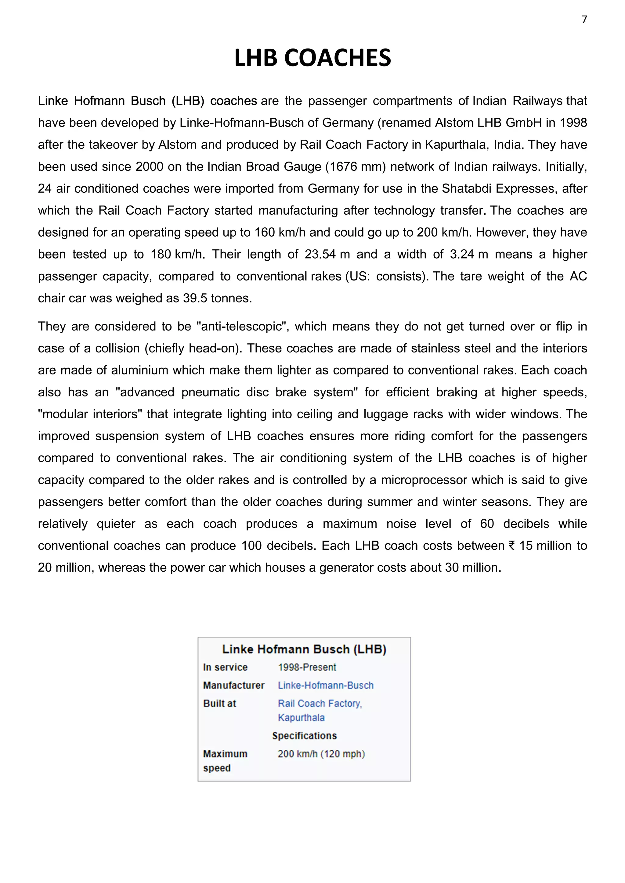
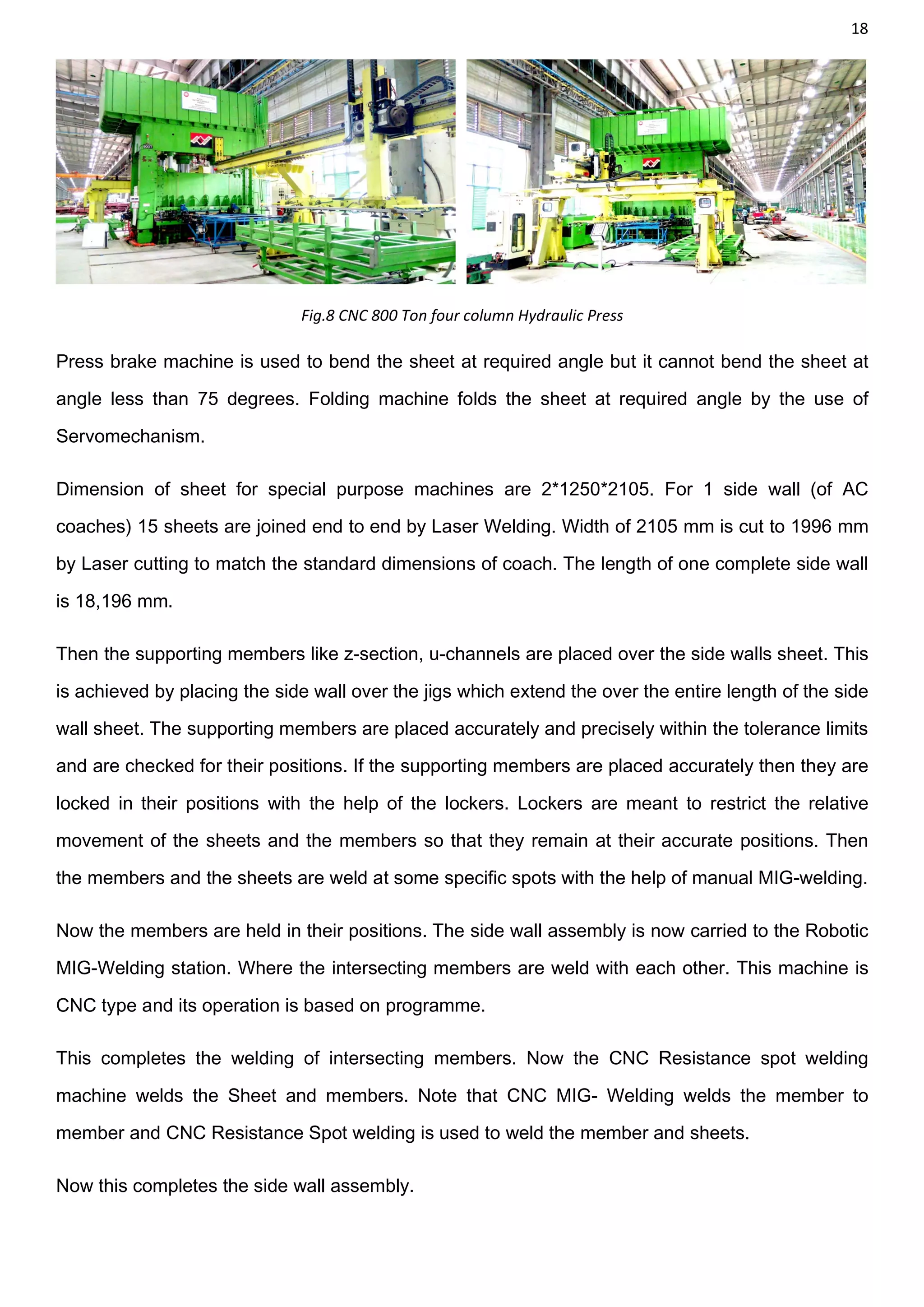
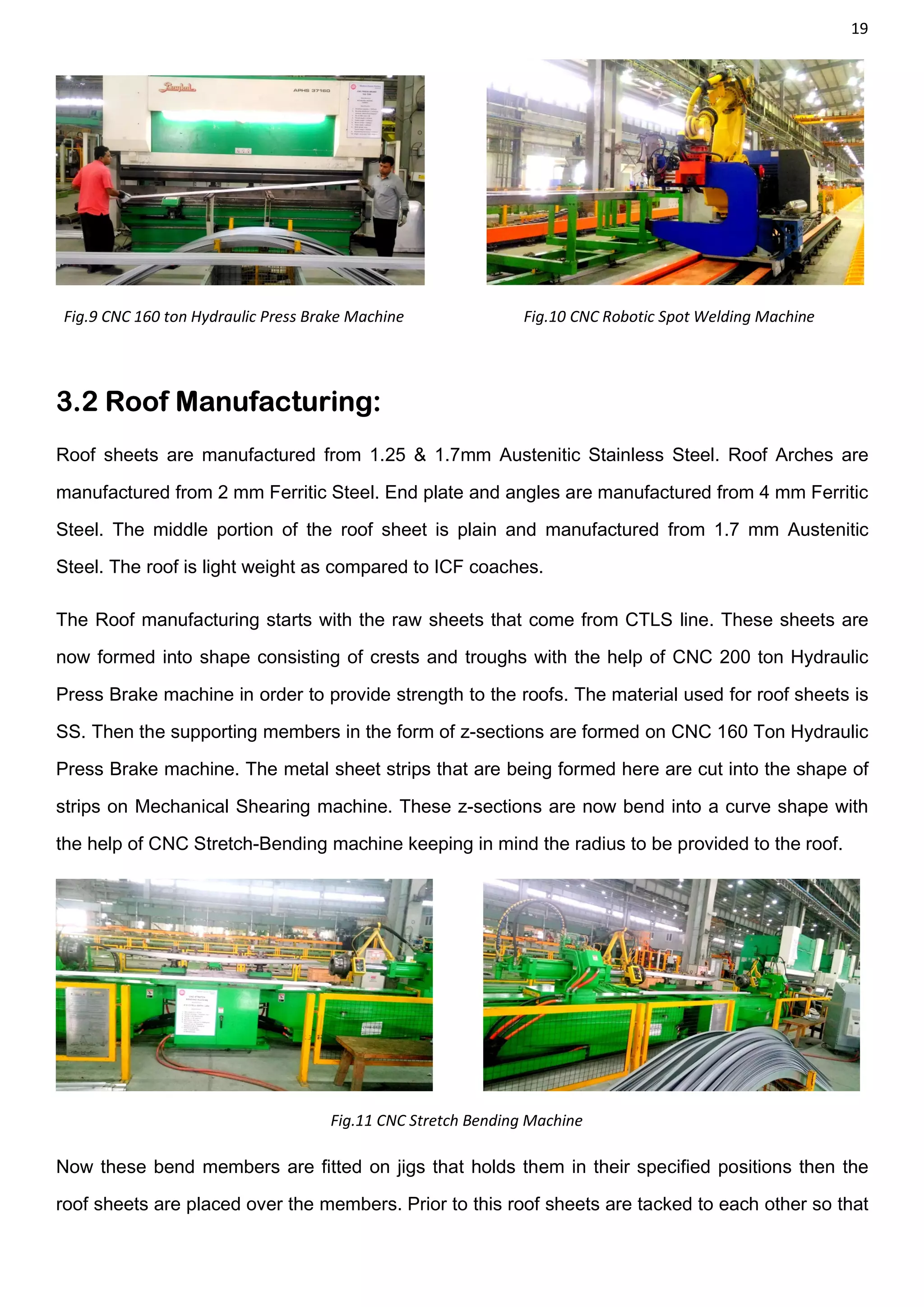
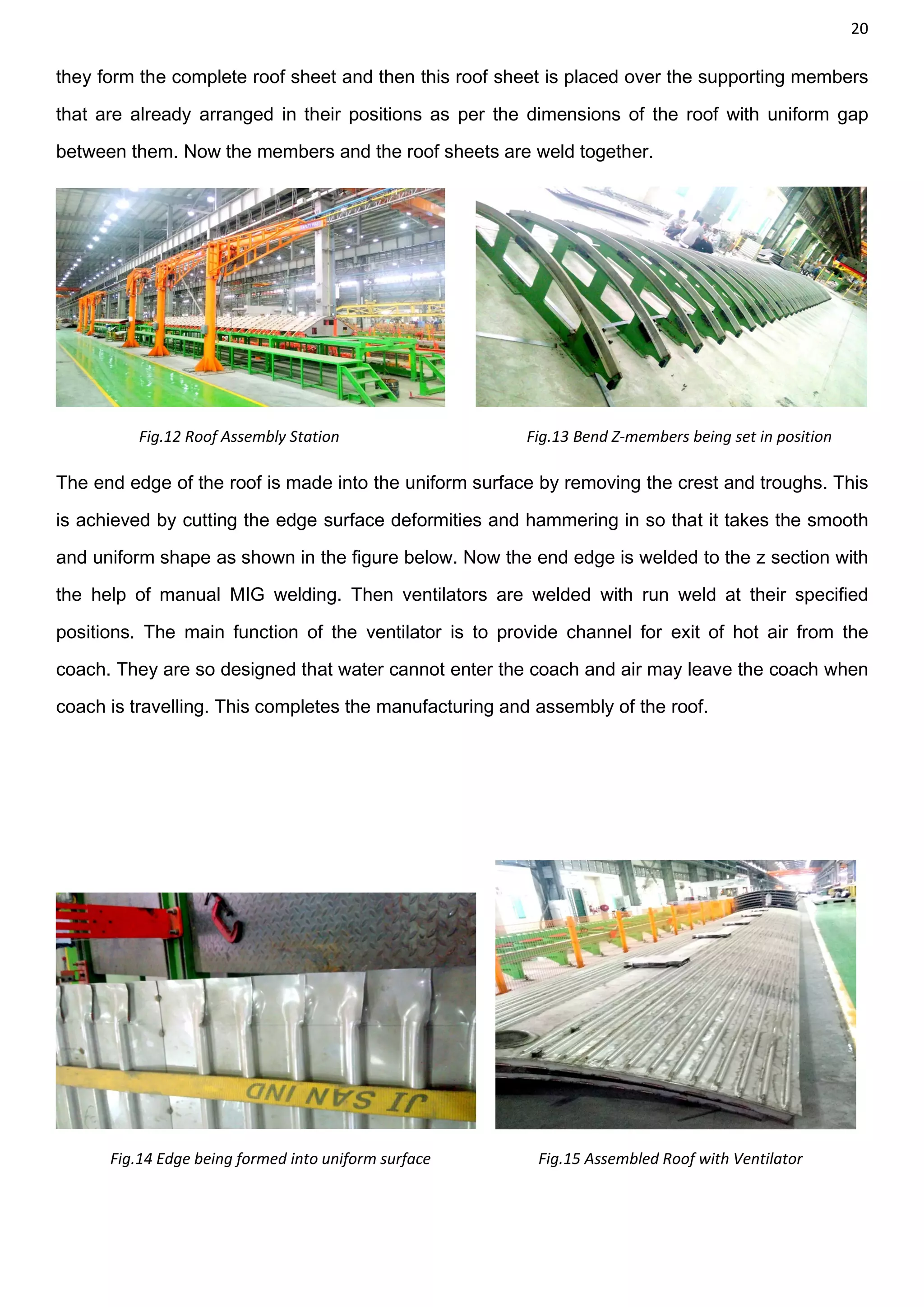
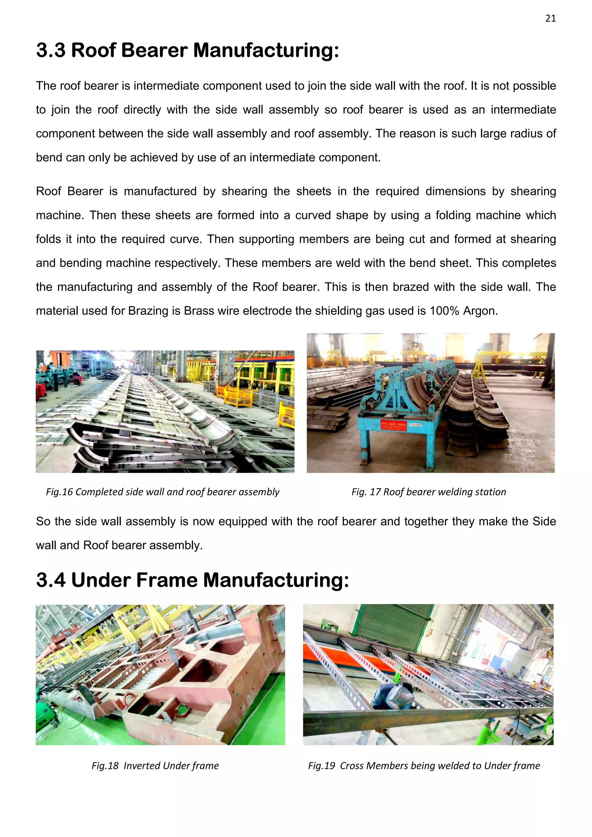
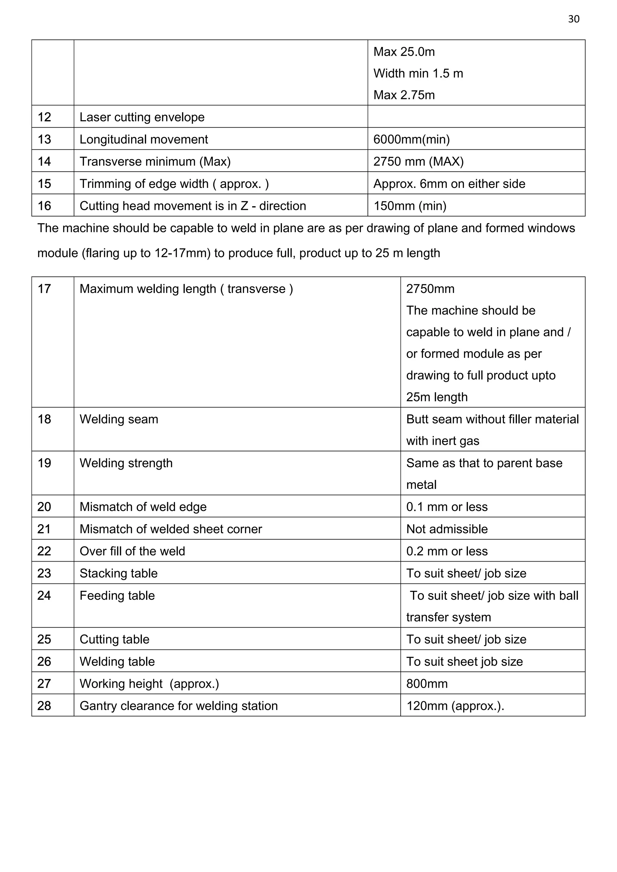
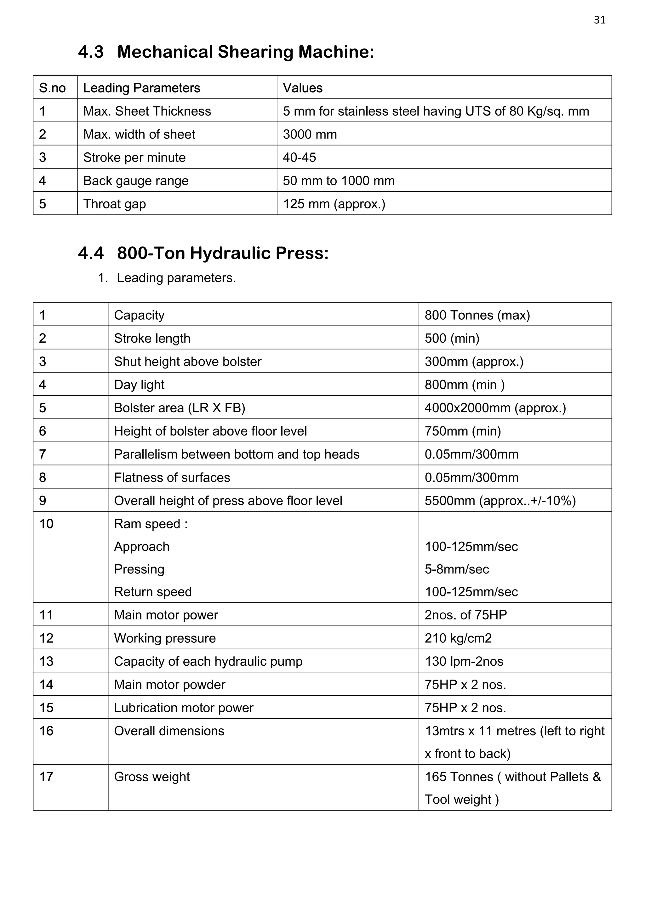
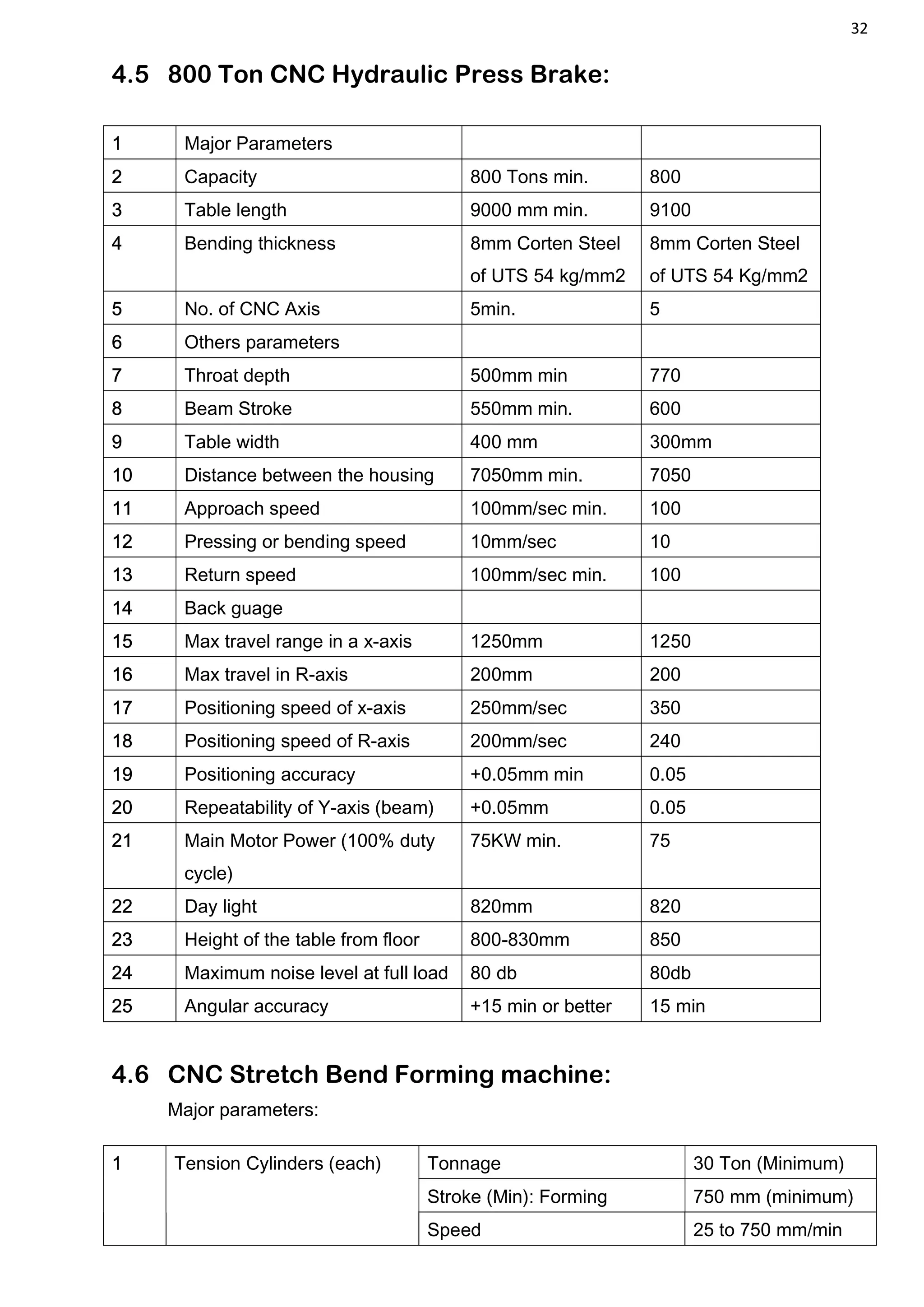
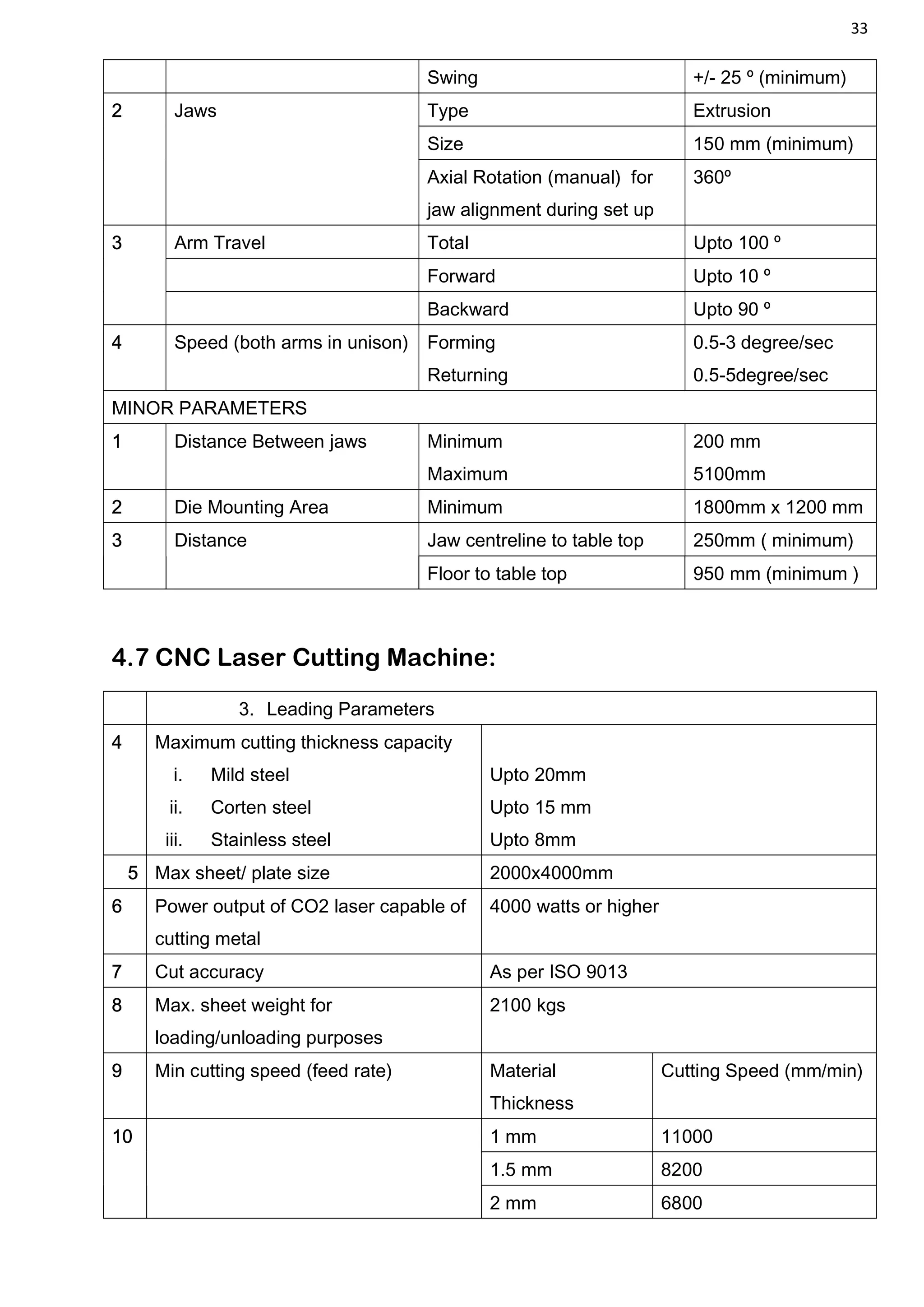
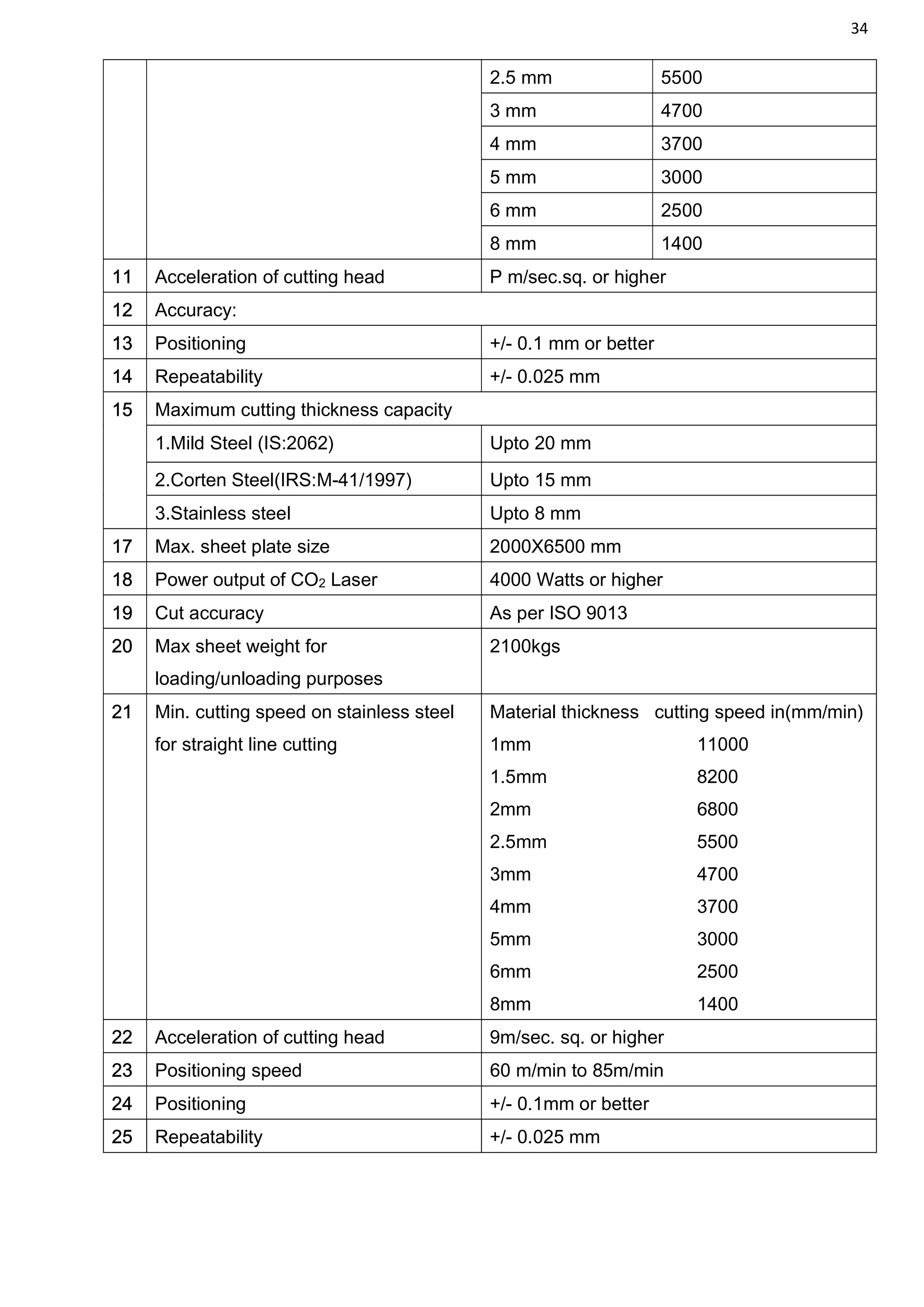
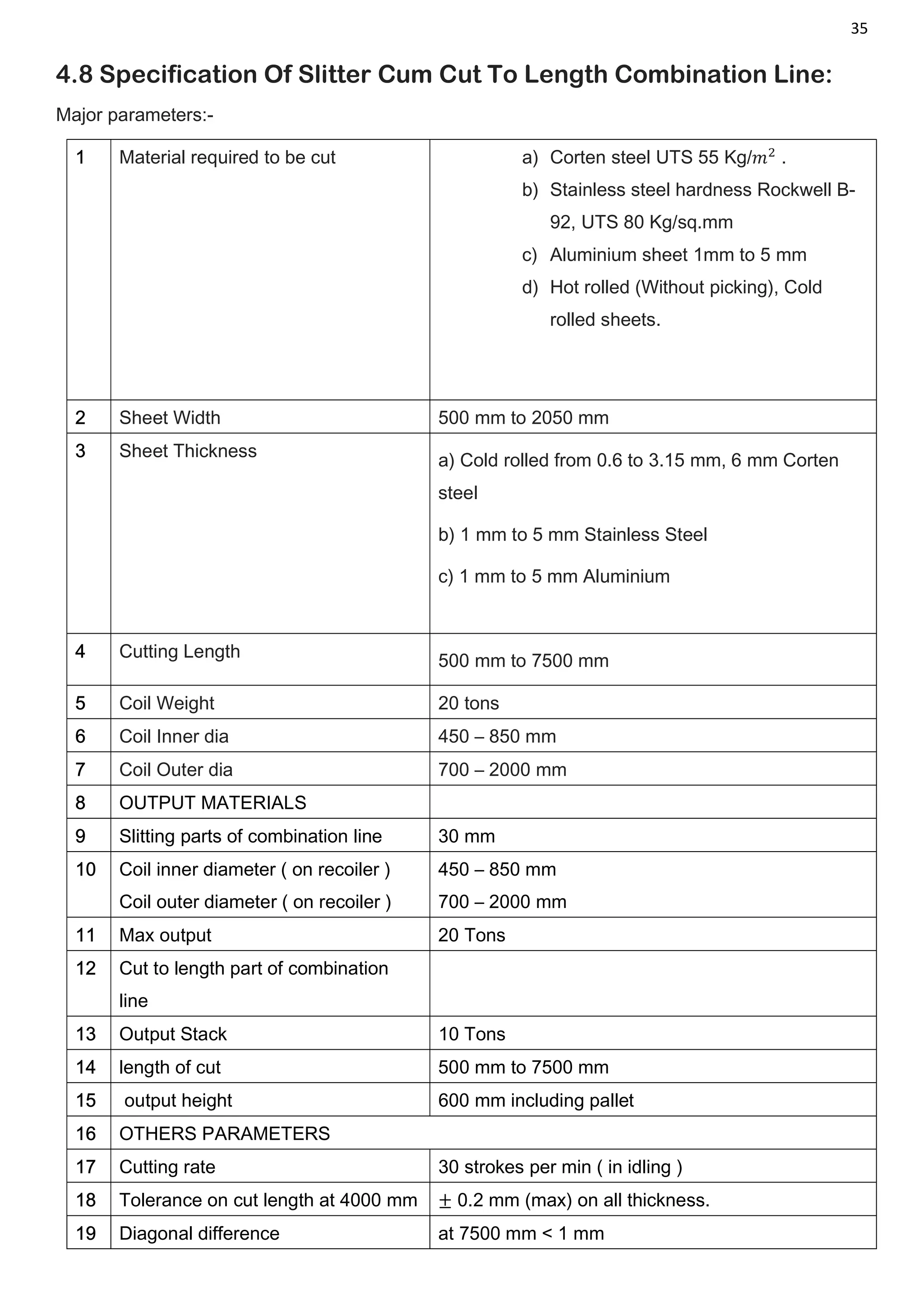
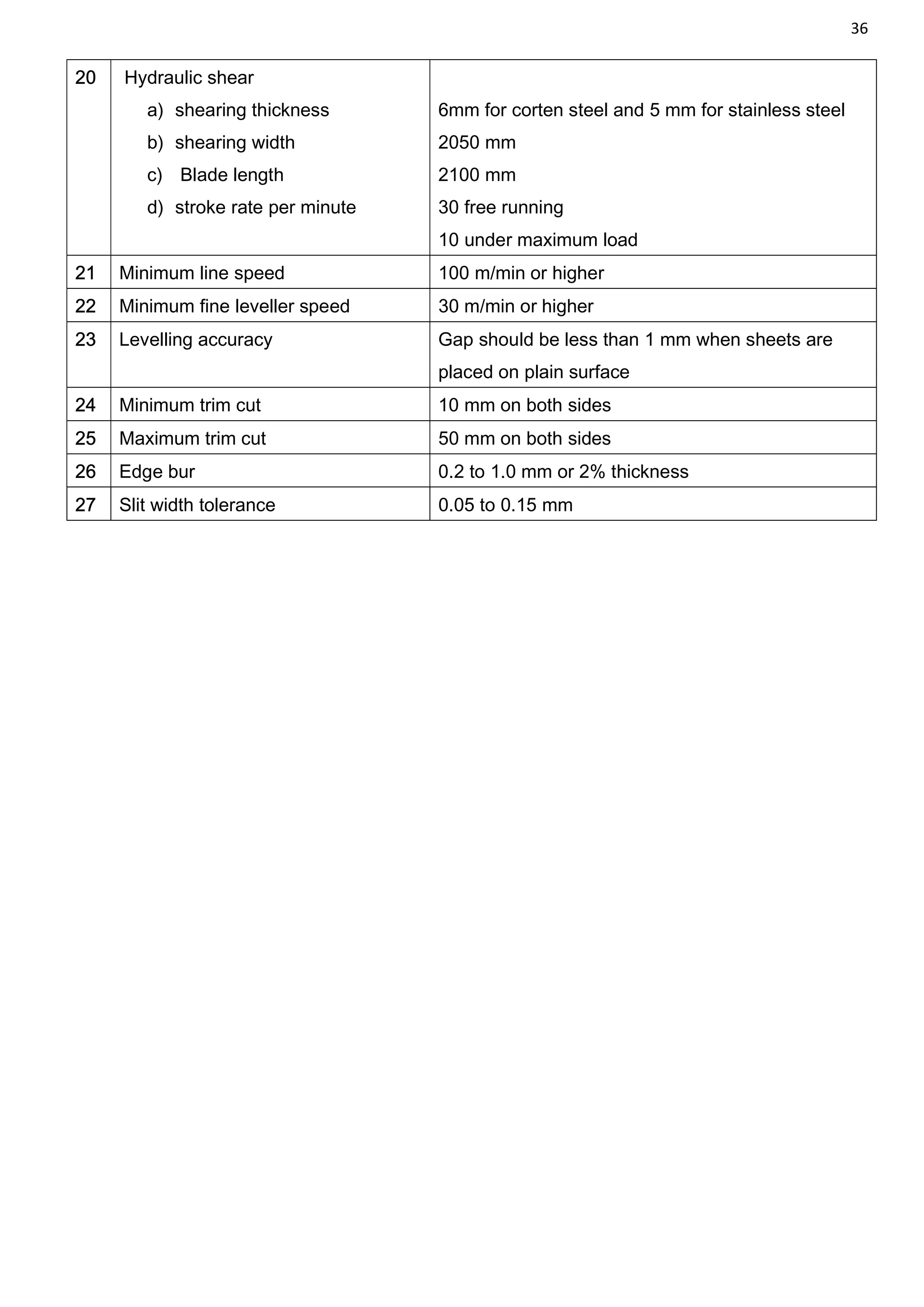
1
Summer Internship (Vocational Training) at
Modern Coach Factory, Raebareli
Project Report on
Study Of Shell Manufacturing Process
at MCF/RBL
Under the guidance of: Submitted by:
Mr. Umesh Singh Shikhar Gupta
(Senior Section Engineer, Training) (B.Tech/ME/3rd
yr/1403040099)
(IPEC, Ghaziabad)
2
Acknowledgement
During the summer vacation at the end of my 3rd year of Mechanical Engineering, I have
undergone the Summer Internship at the Modern Coach Factory, Raebareli from 20th June 2017 to
12th July 2017. During this period I visited different Sections and Shops of interest. In addition to
that I have also completed project on “Study of Shell Manufacturing Process at MCF/RBL” under
the esteemed guidance of Mr. Umesh Singh (SSE Training) and support of many other
department members and staff. The images used in this report are the actual images of various
machines at Shell manufacturing facility at MCF/RBL.
I am very grateful to Mr. Umesh Singh for his kind help and guidance throughout my training.
Based on my experiences and whatever I learned in this industrial training, here I am presenting
the report of my Summer Internship and project work completed at Modern Coach Factory, Rae
Bareli.
3
Preface
No professional studies are considered complete without practical experience. Therefore it is
important for an engineering student to do proper training to get real essence of theory and will be
able to differentiate between theoretical and practical approaches.
Creation of this report is influenced by numerous persons working under the esteemed
organization established by Indian Government. It is an archetype of best Modern Coach
Manufacturing Facility of India. As engineer the training experience have explored another
dimension and platform of our thinking.
Of the various shops located at MCF/RBL viz. Wheel shop, Furnishing Shop, Bogie Shop, Coach
Blasting shop, Paint shop etc. We will restrict our discussion to Shell Fabrication Shop only. This
project enables us to know the processes involved in the manufacturing of Modern LHB coaches
being manufactured at MCF/RBL. The manufacturing of LHB coaches is a complex and critical
process in itself, it involves use of different mechanical processes carried out with the help of
different machines mostly of which are automated and are CNC type, very little work is carried out
manually. In Shell Fabrication Shop metal sheets of different thicknesses are used as basic
material for manufacturing different parts of the coaches these parts are later assembled and
welded together. This completes skeleton or Shell of the coaches. This is an overview and we will
go into details of each process involved in the manufacturing operation of shell in the following
part.
-Shikhar Gupta
4
Contents:
1. Introduction 05
1.1 History 05
1.2 Overview 05
1.3 Production 06
1.4 Various Shops/Sections 06
2. LHB coaches 07
2.1 History 08
2.2 Usage 09
2.3 Production 10
2.4 Technical Details 12
2.4.1 Bogies 12
2.4.2 Couplers 12
2.4.3 Air Conditioning 12
2.4.4 Water Supply and disposal 12
2.4.5 Toilets 13
2.4.6 Pantry 13
2.4.7 Other equipment 14
3. Shell Manufacturing 15
3.1 Side wall manufacturing 15
3.2 Roof manufacturing 19
3.3 Roof bearer manufacturing 21
3.4 Under frame manufacturing 21
3.4.1 Centre Buffer Coupler 24
3.5 Assembly of Shell 25
3.6 Skin Tensioning of Shell 26
4. General Specifications of various machines discussed 28
4.1 Skin Tensioning Equipment 28
4.2 CNC Laser Cutting and Welding Machine 28
4.3 Mechanical Shearing machine 31
4.4 800-Ton Hydraulic Press 31
4.5 800-Ton CNC Hydraulic Press Brake 32
4.6 CNC Stretch Bend Forming Machine 32
4.7 CNC Laser Cutting Machine 33
4.8 Cut to Length cum Slitter line 35
5
Introduction
Modern Coach Factory, Raebareli (earlier Rail Coach Factory, Raebareli) is a rail coach
manufacturing unit of the Indian Railways at Lalganj near Raebareli in Uttar Pradesh. The factory
is the third facility in India that produces railway compartments besides the Integral Coach
Factory at Perambur in Tamil Nadu and the Rail Coach Factory at Kapurthala in Punjab. The
factory was inaugurated by the UPA chairperson Sonia Gandhi on November 7, 2012.
1.1 HISTORY
The project was approved in the Supplementary Railway Budget for 2006-07. Sonia Gandhi laid
the foundation stone for the factory in February, 2007 and land acquisition for the project
commenced in April, 2007. However, in 2008, following the victory of the Bahujan Samaj Party in
the Uttar Pradesh elections of 2007, the new government under Chief Minister Mayawati cancelled
the land deed for the factory halting construction work there. The Allahabad High Court permitted
the project to proceed after a public interest litigation petition was filed before it. In January 2009,
construction of the factory began again which was inaugurated once again by Sonia Gandhi. The
same month, Indian Railways signed a 99-year land lease agreement with the Government of
Uttar Pradesh. The delay led to the cost of the project rising from an initially estimated ₹1685
crores to about ₹2500 crores.
Now Rail coach factory become Modern coach factory.
1.2 OVERVIEW
The factory has come up on a total area of 541 hectares of land of which 283 was acquired from
private parties. The factory was constructed by the IRCON INTERNATIONAL LIMITED (IRCON).
1450 jobs are to be given to families that were affected by the land acquisition besides the
compensation package and the Lucknow Division of the Northern Railways is expected to
generate another 1000 job opportunities as a result of the factory becoming operational. The
factory adheres to stringent pollution control norms for curbing air pollution and spillage of oils and
employs fume and sewage neutralisation systems.
6
1.3 PRODUCTION:
The factory is expected to manufacture 1000 Linke Holfmann Busch (LHB) coaches annually.
Anubhuti coaches, which are state of the art LHB coaches featuring ergonomically designed
cushioned seats, LCD screens, modular toilets and stylish interiors, announced in the Railway
Budget of 2013 are to be produced at the Rae Bareli coach factory. These coaches will
progressively be introduced on the Shatabdi and Rajdhani Express trains.
1.4 VARIOUS SHOPS/SECTIONS:
1. Shell Fabrication Shop
2. Wheel Shop
3. Bogie Shop
4. Shell Blasting Shop
5. Furnishing Shop
6. Paint Shop
7. Machine Shop
8. Transport Shop
9. Tool Room
10. Finishing Shop
7
LHB COACHES
Linke Hofmann Busch (LHB) coaches are the passenger compartments of Indian Railways that
have been developed by Linke-Hofmann-Busch of Germany (renamed Alstom LHB GmbH in 1998
after the takeover by Alstom and produced by Rail Coach Factory in Kapurthala, India. They have
been used since 2000 on the Indian Broad Gauge (1676 mm) network of Indian railways. Initially,
24 air conditioned coaches were imported from Germany for use in the Shatabdi Expresses, after
which the Rail Coach Factory started manufacturing after technology transfer. The coaches are
designed for an operating speed up to 160 km/h and could go up to 200 km/h. However, they have
been tested up to 180 km/h. Their length of 23.54 m and a width of 3.24 m means a higher
passenger capacity, compared to conventional rakes (US: consists). The tare weight of the AC
chair car was weighed as 39.5 tonnes.
They are considered to be "anti-telescopic", which means they do not get turned over or flip in
case of a collision (chiefly head-on). These coaches are made of stainless steel and the interiors
are made of aluminium which make them lighter as compared to conventional rakes. Each coach
also has an "advanced pneumatic disc brake system" for efficient braking at higher speeds,
"modular interiors" that integrate lighting into ceiling and luggage racks with wider windows. The
improved suspension system of LHB coaches ensures more riding comfort for the passengers
compared to conventional rakes. The air conditioning system of the LHB coaches is of higher
capacity compared to the older rakes and is controlled by a microprocessor which is said to give
passengers better comfort than the older coaches during summer and winter seasons. They are
relatively quieter as each coach produces a maximum noise level of 60 decibels while
conventional coaches can produce 100 decibels. Each LHB coach costs between ₹ 15 million to
20 million, whereas the power car which houses a generator costs about 30 million.
8
2.1 HISTORY:
During 1993-94, Indian Railways decided to look for a passenger coach design which would be
lighter and capable of higher speeds compared to their existing rakes. The main features of the
Railways' specification were high speed light weight coaches to run on the present infrastructure of
the Indian Railways, i.e. the railway, track and environmental conditions in India at an operating
speed of 160 km/h. It was decided by the Railways that the design would first be tried in the Rail
Coach Factory in Kapurthala (RCF), and upon successful completion of this trial, it would be tried
in the Integral Coach Factory in Perambur.
In 1995, after a global selection process, Alstom-LHB received the order from Indian Railways to
design and develop a new passenger coach under a transfer of technology agreement. As part of
the order, Alstom-LHB had to execute two contracts, one for the supply of "Light Weight High
Speed Coaches for Broad Gauge" which includes the development, design and manufacture of 19
AC 2nd Class Chair Cars, 2 AC Executive Class Chair Cars and 3 Generator-cum-Brake vans and
the other contract for the "Technology Transfer" which includes the transfer of technology for
design and manufacturing, the training of Indian Railways personnel in the premises of the
manufacturer and the technical assistance at RCF during the start of production. Out of the 24
coaches imported from Germany, all of them mostly being Air Conditioned chair cars, the first lot
were used for New Delhi-Lucknow-Shatabdi Express on a trial basis. It didn't turn out be
successful as the coaches' wide windows were targets of mischief and stone-pelting. Railways had
to use sealing tapes to tape up the bruised windows. When these rakes were brought into service,
couplers came unstuck and the data collected from the passenger feedback showed that the air
conditioning was not "very effective". They were withdrawn from service and after attending to the
problems, Railways reintroduced them on the New Delhi-Lucknow-Shatabdi Express and proved
successful.
The RCF began to manufacture other variants of LHB design like the air conditioned first class, AC
2 tier sleeper, AC 3 tier sleeper, hot buffet (pantry) car etc., from 2001 to 2002, and rolled out its
first rake in December 2002. The first such rake was introduced for Mumbai-New Delhi Rajdhani
Express in December, 2003. Up to March 2011, 997 LHB coaches were produced by the RCF. All
of these coaches are being used in premier super-fast express trains
like Rajdhani, Shatabdi and Duronto Express and have been offering better passenger
comfort. Soon, all the Duronto trains will be equipped with LHB coaches.
9
2.2 USAGE:
Indian Railways have decided to replace the conventional air-conditioned and non-air-
conditioned Integral Coach Factory made coaches with the LHB coaches in all the trains by the
end of 2017. Presently LHB coaches are seen mostly in premium trains such as Rajdhani
Express, Shatabdi Express, Duronto Express, Double Decker Express, Antyodaya
Express& Humsafar Express owing to high cost of manufacture but gradually non-air-conditioned
trains to have Linke hofmann busch coaches. The non-ac trains which were converted into lhb
rakes were mentioned below (Zone wise):-
Central Railway (CR): Kamayani Express, Kushinagar Express.
Eastern Railway (ER): Akal Takht Express, Ananya Express, Durgiana Express, Jallianwalabagh
Express, Howrah-Anand Vihar SF Express, Kolkata Agra Cantonment Superfast Express, Kolkata-
Ghazipur City Weekly Express, Kolkata-Jaynagar Weekly Express, Poorva Express(via Gaya),
Poorva Express(via Patna), Shabd Bhedi SF Express.
East Coast Railway (ECoR): Bhubaneswar-Anand Vihar Weekly SF Express, Howrah-Puri Weekly
SF Express, Puri-Ahmedabad Express, Purushottam Express.
East Central Railway (ECR): Archana Express, Chennai Egmore-Gaya Weekly SF Express,
Mahabodhi Express, Swatantrata Senani SF Express, Sampoorna Kranti SF Express, Ziyarat
Express.
Northern Railway (NR): Chandigarh Amritsar Intercity Express, Indore-Delhi Sarai Rohilla SF
Intercity Express, Kaifiyat Express, Lucknow Mail.
North Central Railway (NCR): Prayagraj Express.
North Eastern Railway (NER): Gorakhpur-Yesvantpur Express(via Faizabad), Gorakhpur-
Yesvantpur Express(via Gonda), Sant Kabir Dham SF Express, Shiv Ganga Express.
Northeast Frontier Railway (NFR): Bhagat Ki Kothi-Kamakhya Express.
Southern Railway (SR): Bikaner-Kochuveli Express, Chennai Central-Thiruvananthapuram Central
Mail, Cholan Express, Pandian SF Express, Rock Fort (Malai Kottai) Express.
Southern Central Railway (SCR): Vijaywada-Dharmavaram Express, Vijayawada-Secunderabad
InterCity Express.
South Eastern Railway (SER): Howrah-Mumbai CST Weekly SF Express, Howrah-Sainagar Shirdi
SF Express, Santragachi-Anand Vihar T. Weekly SF Express, Shalimar-Visakhapatnam Weekly
SF Express.
10
South East Central Railway (SECR): Bhagat Ki Kothi(Jodhpur)-Bilaspur Express, Bilaspur-Bikaner
Express.
Southern Western Railway (SWR): Anga Express, Yesvantpur-Ahmedabad Weekly Express,
Yesvantpur-Chennai Weekly SF Express.
Western Railway (WR): Ashram Express, Gujarat Sampark Kranti Express, Gujarat Mail, Indore-
Yesvantpur Weekly Express, Karnavati Express, Kochuveli-Indore Weekly Express, Maharashtra
Samprak Kranti Express, Mumbai Bandra Terminus-Ghazipur City Weekly Express, Mumbai
Bandra(T.)-Mahuba Express, Mumbai Bandra(T.)-Mahuva SF Express, Mumbai Bandra(T.)-
Veraval SF Express.
2.3 PRODUCTION
Annual production of LHB coaches is around 400 per year for year 2013-2014.
 During 2010-11, RCF Kapurthala produced 300 coaches. During 2012-13, the total number of
coaches that were produced was 1680, while in 2013-14, RCF was able to increase the
production to 1701 coaches.
 During 2013-14, Integral Coach Factory produced 25 LHB coaches. It plans to increase its
manufacturing capacity of LHB coaches. It has set a target to manufacture 300 LHB coaches
in 2014-15 and reach a capacity of 1000 LHB coaches by 2016-17.
 The planned capacity of Rail Coach Factory, Raebareli is 1000 LHB coaches per year. The
plant is yet to become fully operational.
 A rail coach factory has been sanctioned at Palakkad, Kerala in public private partnership
mode for production of LHB coaches. Once completed, this factory would produce 400
coaches annually.
 Rail coach factory is sanctioned by government and is to be set up at Kolar, Karnataka in
February 2014. The planned capacity of this plant is 500 LHB coaches per year for phase-1
and additional capacity of 500 coaches per year in phase-2.
11
TYPES
 LGS = Second class self-generating
 LS = Second class non self-generating
 LS3 = Second class non self-generating
 LS4 = Second class non self-generating General Seating
 LSCN = Second class 3-tier sleeper
 LWACCW = AC2 Air-conditioned 2-tier sleeping-car (52 berths)
 LWACCN = AC3 Air-conditioned 3-tier sleeping-car (72 berths)
 LWCBAC = Air-conditioned pantry/kitchen/buffet car
 LWFAC = AC1 Air-conditioned first class sleeping-car (24 berths)
 LWFCWAC = Composite coach with air-conditioned AC1 sleeping-compartments and AC2 2-
tier sleeping-compartments
 LWFCZAC = Air-conditioned executive chair car (56 seats)
 LWLRRM = Luggage/generator/brake van
 LWSCN = 3-tier Sleeper for 80 passengers
 LWSCZAC = Air-conditioned chair car (78 seats)
 LWSCZ = Chair car
12
2.4 TECHNICAL DETAILS
2.4.1 Bogies
The FIAT-SIG bogie is a welded H frame type based on the Eurofima standard. The wheel base is
2560 mm, the wheel diameter new 915 mm and at maximum wear 845 mm. Main features of the
bogie are primary suspension with articulated arms and coil springs, secondary suspension of
integral flexicoil type with coil springs and rubber pads on top and bottom, anti-roll bar, vertical and
transverse shock absorbers and anti-hunting dampers. For braking on each axle two disc brakes
with 640 mm diameter, brake cylinders and automatic slack adjuster are provided.
2.4.2 Couplers
The automatic centre buffer coupler of AAR tight lock type at the coach end has a support frame
which provides an anti-climbing protection. The coupler can be opened from the side by a lever.
The design allows the use of screw coupler instead of centre buffer coupler. Therefore a fixing
plate for buffers is also provided. The inter-vehicle coupler for the supply of the 750 V from
the generator car is located below the under-frame. Due to the moving situation 4 brake hoses are
to be used at the coach ends which are brought to two hoses behind the coupler.
2.4.3 Air conditioning
Each coach is equipped with two compact roof-mounted air-conditioning units which have a
cooling capacity of approximately 2x22.5 KW and a heating capacity of 2x6 KW and which are
controlled by a microprocessor. The operating voltage of the unit is 3 phase, 415 V, 50 Hz. Each
unit has 2 refrigerant circuits with hermetic refrigerant compressors, condensers with Copper pipes
and Aluminium fins, evaporators and condenser fans.
The fresh air comes in through the air inlet of the AC unit. The conditioned air is transported in
heat insulated aluminium ducts mounted below the roof and distributed through the perforated
ceiling into the passenger room. The return air flows back through openings above the
compartment door to the AC unit. The entrance area, toilets and pantry are connected to the
exhaust air system.
2.4.4 Water supply and disposal
There are two connected fresh water tanks, which are made of stainless steel, with a total capacity
of 1370 liters for the 3 toilets. The water level is indicated on one tank on each side. The filling can
be made from both sides by one filler for both tanks. Three intermediate water tanks, each with a
capacity of 30 liters, made out of stainless steel are located above the toilets. Two centrifugal
pumps located in a stainless steel casing at the under frame supply the water to the tanks. One of
13
the 415 V pumps is always kept running, while the other is kept on standby. After each switch is
off the other pump will work.
Below each toilet, a 40 litre waste water tank is provided in which toilet waste is collected when the
coach is at standstill. It gets opened with a pneumatically operated sliding valve when a defined
speed is reached. The junction box for the inter-vehicle coupler is visible.
Control panel for water system of an Control panel for Air Conditioning in an LHB
LHB rake in a Rajdhani express train rake of Rajdhani Express
2.4.5 Toilets
The coaches are equipped with "controlled discharge toilet system" (CDTS). By the means of this
system, a toilet in the coach would become functional only when the speed of the coach crosses
30 kmph, which is said to help in avoiding the soiling of the track at the railway stations. Later on,
CDTS was discarded for an environmental friendly alternative, "Bio-Toilet", designed in
collaboration with DRDO. Both eastern (squat) and western styles of toilets are provided. One side
of the toilet is provided with a wash basin with water tap and sensor button, a soap dispenser, a
mirror, an ash tray and a waste bin. On the other side there is the toilet itself, a water tap with
mug, a handhold, the toilet paper holder and the sensor button for the toilet flush. The window in
the toilet can be opened in the upper half. The toilet doors are of folding type to use the available
space to an optimum.
2.4.6 Pantry
Each vehicle is equipped with a pantry for storing cold and hot meals which are to be served to the
passengers at their seats. In the gangway between the passenger room door and the entrance is
on one side the pantry and on the other side the storage area. The pantry is closed by a double
leaf sliding door and the storage area by roller shutters. On the left side, a 15 litre water boiler, an
11 litre soup-warmer, a sink, and racks are provided. The other side is equipped with three hot
cases, the bottle cooler, the refrigerator and the deep freezer for the 78 passengers. The storage
area gives space for racks and also for the serving trolley.
14
2.4.7 Other equipment
On the outside wall of the toilet a waste bin and a fire extinguisher are located. The fire
extinguisher on the power panel end is filled with carbon dioxide, the one on the other end with
water. The vestibule is of UIC rubber type. The vestibule door is a double leaf stainless steel
sliding door. On the left side the socket of the local 415 V supply is located. A 60 kVA transformer
with copper winding transforms the power given by the generator car from 750 V to 415 V. All
brake control equipment is centrally not at all located in a brake container. A main brake pressure
reservoir of 125 litres and a service pressure reservoir of 75 litres are provided.
15
SHELL MANUFACTURING
The manufacturing of the shell is accomplished with the assembly of Under frame, Side Walls,
Roof and Roof Bearer, End-Wall Assembly.
The raw metal comes in the form of rolls of the metal sheets. Three types of metallic sheets are
used at MCF/RBL viz.
SSA (Stainless Steel Austenitic)
SSF (Stainless Steel Ferritic)
CS (Corten Steel)
The main use of Corten Steel is due to its strength is more than Mild Steel, CS has UTS of 450-
480 MPa and Mild Steel has UTS of 380 MPa.
3.1 Side Wall Manufacturing:
The side walls are manufactured by MIG Welding of sheets to achieve low heat inputs, less
distortion and negligible shrinkage. The thickness of sidewall sheets is 2mm. The other important
features are:
 Door frames are part of sub-assembly of side wall but fabricated separately to take up
compensation of tolerance in whole side wall.
 Positive interlocking between all horizontal and vertical members.
 Reduced sidewall thickness of 60mm from 90mm.
 Better geometry integrity and strength.
Side wall is welded with under frame by V grooving of sole bar. Meta cot silver grey weld able
primer is applied to avoid bimetallic corrosion, the welding is done by magnetic track welding and
grinding of welded joint is done to ensure smoothness. The design of side wall has eliminated turn
under to avoid accumulation of water, muck and resultant corrosion. The approach for sand
blasting and painting is better.
These Sheets from CTLS are now fed to CTLS machine i.e. cut to length cum slitter machine.
CTLS uncoils the sheet and straightens the sheets without altering actual thickness and other
parameters of the sheet. After straightening the sheet Slitting operation is performed on the sheet.
16
Fig.1 Cut to Length cum Slitter Line
Fig.2 Slitter of CTLS line
The SSA comes in the size of 1.25 mm, 1.75 mm; SSF comes in the sizes of 2 mm, 4 mm, 6 mm
and Corten Steel comes in the size of 3.16 mm, 4 mm, 5 mm, 6 mm. When the sheets are
processed in the CTL line, the processed sheets are being sent to three stations viz. Shearing
machine, Laser Cutting machine and Press brake machine (800 tonnes, 160 tonnes, 200 tonnes,
400tonnes).
. Fig.3 CNC Laser Cutting Station Fig.4 CNC Laser Cutting Machine
17
LCM (Laser Cutting Machine) is used to cut complicated types of profile with a help of the Laser.
At MCF/RBL LCM is used to cut z-members, U-channels, T- floor, Angle, Rib, Roof flange,
brackets, etc.
Fig.5 Pick n Place Robot of LCWM Fig.6 Welding and cutting head of LCWM
LCWM (Laser Cutting and Welding machine) is used to cut the complicated profiles like window
panels of 3-Tier and 2-Tier. It cuts the required complicated profile with great accuracy and finish.
The operation of LCWM is automated and the machine is CNC type.
Fig.7 Welding Head performing laser welding of butt joined sheets
When the window panels are cut from side wall sheet then the sheet is send to the CNC 800 Ton
Hydraulic Press Machine to form the window curve of GS, SLR type coaches.
18
Fig.8 CNC 800 Ton four column Hydraulic Press
Press brake machine is used to bend the sheet at required angle but it cannot bend the sheet at
angle less than 75 degrees. Folding machine folds the sheet at required angle by the use of
Servomechanism.
Dimension of sheet for special purpose machines are 2*1250*2105. For 1 side wall (of AC
coaches) 15 sheets are joined end to end by Laser Welding. Width of 2105 mm is cut to 1996 mm
by Laser cutting to match the standard dimensions of coach. The length of one complete side wall
is 18,196 mm.
Then the supporting members like z-section, u-channels are placed over the side walls sheet. This
is achieved by placing the side wall over the jigs which extend the over the entire length of the side
wall sheet. The supporting members are placed accurately and precisely within the tolerance limits
and are checked for their positions. If the supporting members are placed accurately then they are
locked in their positions with the help of the lockers. Lockers are meant to restrict the relative
movement of the sheets and the members so that they remain at their accurate positions. Then
the members and the sheets are weld at some specific spots with the help of manual MIG-welding.
Now the members are held in their positions. The side wall assembly is now carried to the Robotic
MIG-Welding station. Where the intersecting members are weld with each other. This machine is
CNC type and its operation is based on programme.
This completes the welding of intersecting members. Now the CNC Resistance spot welding
machine welds the Sheet and members. Note that CNC MIG- Welding welds the member to
member and CNC Resistance Spot welding is used to weld the member and sheets.
Now this completes the side wall assembly.
19
Fig.9 CNC 160 ton Hydraulic Press Brake Machine Fig.10 CNC Robotic Spot Welding Machine
3.2 Roof Manufacturing:
Roof sheets are manufactured from 1.25 & 1.7mm Austenitic Stainless Steel. Roof Arches are
manufactured from 2 mm Ferritic Steel. End plate and angles are manufactured from 4 mm Ferritic
Steel. The middle portion of the roof sheet is plain and manufactured from 1.7 mm Austenitic
Steel. The roof is light weight as compared to ICF coaches.
The Roof manufacturing starts with the raw sheets that come from CTLS line. These sheets are
now formed into shape consisting of crests and troughs with the help of CNC 200 ton Hydraulic
Press Brake machine in order to provide strength to the roofs. The material used for roof sheets is
SS. Then the supporting members in the form of z-sections are formed on CNC 160 Ton Hydraulic
Press Brake machine. The metal sheet strips that are being formed here are cut into the shape of
strips on Mechanical Shearing machine. These z-sections are now bend into a curve shape with
the help of CNC Stretch-Bending machine keeping in mind the radius to be provided to the roof.
Fig.11 CNC Stretch Bending Machine
Now these bend members are fitted on jigs that holds them in their specified positions then the
roof sheets are placed over the members. Prior to this roof sheets are tacked to each other so that
20
they form the complete roof sheet and then this roof sheet is placed over the supporting members
that are already arranged in their positions as per the dimensions of the roof with uniform gap
between them. Now the members and the roof sheets are weld together.
Fig.12 Roof Assembly Station Fig.13 Bend Z-members being set in position
The end edge of the roof is made into the uniform surface by removing the crest and troughs. This
is achieved by cutting the edge surface deformities and hammering in so that it takes the smooth
and uniform shape as shown in the figure below. Now the end edge is welded to the z section with
the help of manual MIG welding. Then ventilators are welded with run weld at their specified
positions. The main function of the ventilator is to provide channel for exit of hot air from the
coach. They are so designed that water cannot enter the coach and air may leave the coach when
coach is travelling. This completes the manufacturing and assembly of the roof.
Fig.14 Edge being formed into uniform surface Fig.15 Assembled Roof with Ventilator
21
3.3 Roof Bearer Manufacturing:
The roof bearer is intermediate component used to join the side wall with the roof. It is not possible
to join the roof directly with the side wall assembly so roof bearer is used as an intermediate
component between the side wall assembly and roof assembly. The reason is such large radius of
bend can only be achieved by use of an intermediate component.
Roof Bearer is manufactured by shearing the sheets in the required dimensions by shearing
machine. Then these sheets are formed into a curved shape by using a folding machine which
folds it into the required curve. Then supporting members are being cut and formed at shearing
and bending machine respectively. These members are weld with the bend sheet. This completes
the manufacturing and assembly of the Roof bearer. This is then brazed with the side wall. The
material used for Brazing is Brass wire electrode the shielding gas used is 100% Argon.
Fig.16 Completed side wall and roof bearer assembly Fig. 17 Roof bearer welding station
So the side wall assembly is now equipped with the roof bearer and together they make the Side
wall and Roof bearer assembly.
3.4 Under Frame Manufacturing:
Fig.18 Inverted Under frame Fig.19 Cross Members being welded to Under frame
22
Under frame is the base of any coach on which the coach body is being build. It must be
sufficiently strong and resistant. Main components of Under Frame are:
 Front part made by joining head stock and body bolster.
 Two side sills of sole bar of AC Chair car are made of section 238x65x6.
 Two side sills of sole bar of AC Power car are made of section 238x65x8.
 Two side sills of sole bar of both above coaches are made of section 238x65x4
 Two main cross members - 6 mm thick
 Frame – cross members made of folded channel sections 140x50x4
 Floor is made of corrugated sheets of 1.25 mm thickness
 Corrugated trough floor is plug welded from top with the cross members.
Fig.20 Diagram Showing various sections of a Shell
Cross members are held at their respective positions also brackets are inserted between them.
These cross members are then tacked manually to fix their positions. After this under frame is
advanced to the Robotic MIG Welding station where robotic arms perform the continuous run
welding between mating parts, these robotic arms are controlled by a CNC controller based on a
program.
23
Fig.21 CNC Robotic MIG Welding station
Then the floor made of corrugated sheets of 1.25 mm thick is plug weld from the top to the cross
members. Then the under frame is inverted and various components like yaw damper, water tank
mounting brackets are welded at their respective positions. Several other members are also
welded to under frame which is used to accommodate bogies. This completes manufacturing and
assembly of under frame.
Up to this, whatever we have studied were the major components of shell. But apart from these in
the completion of the shell body some ready to assemble components like End wall Assembly is
weld to close the ends of the coach. End wall is made of ferritic steel. To reduce its weight holes
provided in all stiffeners. The projection of side walls towards end is more. This result into more
availability of space for passengers and reduction in the gap between two coaches, thereby
reduced wind gap resistance and turbulence. The gap between two end walls is 300 mm only.
The end wall assembly is not manufactured at RCF/RBL but is brought in ready to install form and
it does not require any type of machining operation but is simply installed.
24
Fig.22 End Wall assembly
3.4.1 Centre Buffer coupler: Centre Buffer coupler is installed on the under frame. It is
brought as a separate unit ready to install and lifted with the help of EOT crane and placed in its
accurate position.
The coupler provides a means of mechanically connecting individual adjacent vehicles to make a
train. The coupler is located at both ends of each vehicle. When connected to a coupler of an
adjacent vehicle, it allows the vehicles to move independently to accommodate track curvature
and elevation change while remaining connected (coupled) together.
The coupler is opened manually using the coupler operating rod and is closed automatically when
the couplers on adjacent vehicles are mated. The coupler automatically locks when fully mated.
LHB coaches have been provided with tight lock centre buffer couplers instead of screw coupling.
Couplers are AAR-H type and have anticlimbing features because of vertical interlocking.
Couplers have adequate strength for:
 Satisfactory hauling of a train of 26 coaches at 110 kmph
 Satisfactory hauling of a train of 18 coaches at 160 kmph
Coupling is possible under angular misalignment both horizontally and vertically. The coupler
permits coupled trains to negotiate vertical and horizontal curves and allows rotational
movements. The draw gear ensures cushioning effective in both buff and draft.
Fig.23 Schematic of CBC Fig.24 Actual CBC installed on underframe
25
3.5 Assembly of Shell:
We have Under frame, Side walls, Roof and Roof bearer, End wall assembly as complete
individual units. Now the only task remaining is their assembly. Various steps are involved in the
assembly of a shell are. It starts with the mounting of under frame, side walls are being carried
from their stations to the assembly station with the help of EOT crane. This side wall is positioned
and placed over the edge of under frame. Initially side walls are supported by welding them with
steel rods which are welded to the floor for making sure that the side wall is perfectly vertical and
no further displacement or movement of side wall from its specified position is possible. The
mating edge of side wall and under frame is tacked at some points manually by using MIG welding
equipment as shown in figure 25 and 26. Manual tacking at specific distances is required to
ensure the perfect mating edge for feeding it to the robotic MIG welding machine which performs
continuous run welding.
Fig.25 Manual MIG welding equipment Fig.26 MIG welding equipment console
Now the roof is being carried with the help of EOT crane to the shell assembly station and is put
over the side walls. Remember the roof bearer is already brazed to the side wall. Roof is also
tacked at different points with the help of manual MIG welding equipment. This manual tacking
ensures to resist the movement of roof over the side walls. Now end wall assembly is being weld
to the open end portion of the shell.
The shell is now moved to the CNC MIG welding machine which welds the edges and makes the
whole shell into a single solid shell. This machine uses two robotic arms whose operation is based
on a program fed to controller of CNC machine. It uses nitrogen as a shielding gas.
26
Fig.27 CNC MIG welding station Fig.28 Manual tacking of side wall and under frame
This completes the assembly of Shell.
3.6 Skin Tensioning of Shell:
After the assembly of shell, the final operation which is done is Skin Tensioning.
Fig.29 Skin Tensioning Equipment Fig.30 Hole plate
Fig.32 Skin Tensioning Torch Fig.34 A worker doing skin tensioning
27
Skin Tensioning is carried out by arranging the shell body under Skin Tensioning equipment. The
electro-magnet shown with the green colour in fig.29 is raised up to the level of shell body then the
power supply is turned ON for the electro-magnet which activates the magnetic field result of
which the electro-magnet gets stuck with the shell body. On the inner side of the shell body the
holed iron plate is made to stick to the side wall under the action of electromagnet. Then the
tensioning torch is ignited and the side wall metal sheet visible from these holes is heat treated by
the action of hot gases at the nozzle of torch. This process completes the assembly of the shell.
28
General Specifications
of various machines discussed
4.1 Skin Tensioning Equipment:
S.no Parameters Values
1 Size of Electomagnet 1M X 1M X 200mm
2 Magnetic Force 12000Kgs (120,000N)
3 Input power to control panel 400V +/-10%, 50+/-3% Hz
4 Output power of control panel for magnet 110 Volt DC
5 Control of Crane Pendant
6 Input power to crane 400V +10/-15%, 50 Hz +/-3%
7 Lifting speed of hoists 1-4m/min
8 Speed of longitudinal Travel 20m/min. Max
9 Cross Travel Manual
10 Long travel range 33 meters
11 Gross weight of electromagnet Approx 1010 Kgs
12 HP and RPM of hoisting motors 1.5 KW motor/1440 rpm
4.2 CNC Laser Cutting and Welding machine:
1. Major parameters
1.1 Maximum cutting and welding thickness capacity:-
i. Stainless steel : 0.8 mm to 3 mm.
ii. The capability and providing out shell be as indicated below :
S.No. Capacity Raw materials specification for providing out of components
as per clause 1.1
1 Ferritic stainless
steel
FERRITIC STEEL SHEET WIDTH 1250mm GRADE
X2CrNi12(409M) TABLE 1& 2, RDSO SPEC NO. C-K 201,
HEAT TREATMENT CONDOITION 2B AS PER TABLE-5
2 Austenitic stainless
steel
AUSTENITIC STEEL SHEET WIDTH 1250mm GRADE
X5CrNi1810(304) TABLE 1& 2, RDSO SPEC NO. C-K 201,
HEAT TREATMENT CONDOITION 2B AS PER TABLE-5
29
STAINLESS STEEL SHEET WIDTH 1250mm GRADE
X2CrNIN18-7 (AISI301 LN) RDSO SPEC NO. C-K
201,TABLE- 1,2,3&4, (REPLACED) HEAT TREATMENT
CONDOITION 2B AS PER TABLE-5
3 Corten steel IRS:M41-97
1.2 Sheet size limits shall be as below
1.2.1 The machine should be able to handle and to do cutting/welding on any sheet of size as
indicated below
This sheet size can be raw sheet or smaller sheets welded together to obtain ant intermediate size
between these limits. It may have plane or have flared windows . Flaring can be up to 17 mm
height.
1 Power output of CO2 laser 3000 watts or higher capable of
cutting and welding as per cl 1.1
2 Cut and weld accuracy As per DIN 2310-pt. V
3 Min. Positioning speed programmable 60/min.
4 Accuracy of laser cutting and welding
5 Positioning accuracy over 500 mm +/- 0.03mm or better
6 Repeatability +/- 0.015 mm or better
7 Overall accuracy over total work area As per VDI/GHQ norms
8 Cutting speed (Min)
With Oxygen
With Nitrogen
6-7 m/min, or more
2-3 m/min, or more
9 Welding speed for sheet materials (stainless steel )
Acceleration Rate (Min).
2-3m/ min, or more
3m/sec. square
10 Incremental path programming +/-0.01mm
11 Size of welded product Length min 1.5 m
Sheet size Min size Max size
Transverse 1.5 m 2.51m
Longitudinal 1 m 4m
30
Max 25.0m
Width min 1.5 m
Max 2.75m
12 Laser cutting envelope
13 Longitudinal movement 6000mm(min)
14 Transverse minimum (Max) 2750 mm (MAX)
15 Trimming of edge width ( approx. ) Approx. 6mm on either side
16 Cutting head movement is in Z - direction 150mm (min)
The machine should be capable to weld in plane are as per drawing of plane and formed windows
module (flaring up to 12-17mm) to produce full, product up to 25 m length
17 Maximum welding length ( transverse ) 2750mm
The machine should be
capable to weld in plane and /
or formed module as per
drawing to full product upto
25m length
18 Welding seam Butt seam without filler material
with inert gas
19 Welding strength Same as that to parent base
metal
20 Mismatch of weld edge 0.1 mm or less
21 Mismatch of welded sheet corner Not admissible
22 Over fill of the weld 0.2 mm or less
23 Stacking table To suit sheet/ job size
24 Feeding table To suit sheet/ job size with ball
transfer system
25 Cutting table To suit sheet/ job size
26 Welding table To suit sheet job size
27 Working height (approx.) 800mm
28 Gantry clearance for welding station 120mm (approx.).
31
4.3 Mechanical Shearing Machine:
S.no Leading Parameters Values
1 Max. Sheet Thickness 5 mm for stainless steel having UTS of 80 Kg/sq. mm
2 Max. width of sheet 3000 mm
3 Stroke per minute 40-45
4 Back gauge range 50 mm to 1000 mm
5 Throat gap 125 mm (approx.)
4.4 800-Ton Hydraulic Press:
1. Leading parameters.
1 Capacity 800 Tonnes (max)
2 Stroke length 500 (min)
3 Shut height above bolster 300mm (approx.)
4 Day light 800mm (min )
5 Bolster area (LR X FB) 4000x2000mm (approx.)
6 Height of bolster above floor level 750mm (min)
7 Parallelism between bottom and top heads 0.05mm/300mm
8 Flatness of surfaces 0.05mm/300mm
9 Overall height of press above floor level 5500mm (approx..+/-10%)
10 Ram speed :
Approach
Pressing
Return speed
100-125mm/sec
5-8mm/sec
100-125mm/sec
11 Main motor power 2nos. of 75HP
12 Working pressure 210 kg/cm2
13 Capacity of each hydraulic pump 130 lpm-2nos
14 Main motor powder 75HP x 2 nos.
15 Lubrication motor power 75HP x 2 nos.
16 Overall dimensions 13mtrs x 11 metres (left to right
x front to back)
17 Gross weight 165 Tonnes ( without Pallets &
Tool weight )
32
4.5 800 Ton CNC Hydraulic Press Brake:
1 Major Parameters
2 Capacity 800 Tons min. 800
3 Table length 9000 mm min. 9100
4 Bending thickness 8mm Corten Steel
of UTS 54 kg/mm2
8mm Corten Steel
of UTS 54 Kg/mm2
5 No. of CNC Axis 5min. 5
6 Others parameters
7 Throat depth 500mm min 770
8 Beam Stroke 550mm min. 600
9 Table width 400 mm 300mm
10 Distance between the housing 7050mm min. 7050
11 Approach speed 100mm/sec min. 100
12 Pressing or bending speed 10mm/sec 10
13 Return speed 100mm/sec min. 100
14 Back guage
15 Max travel range in a x-axis 1250mm 1250
16 Max travel in R-axis 200mm 200
17 Positioning speed of x-axis 250mm/sec 350
18 Positioning speed of R-axis 200mm/sec 240
19 Positioning accuracy +0.05mm min 0.05
20 Repeatability of Y-axis (beam) +0.05mm 0.05
21 Main Motor Power (100% duty
cycle)
75KW min. 75
22 Day light 820mm 820
23 Height of the table from floor 800-830mm 850
24 Maximum noise level at full load 80 db 80db
25 Angular accuracy +15 min or better 15 min
4.6 CNC Stretch Bend Forming machine:
Major parameters:
1 Tension Cylinders (each) Tonnage 30 Ton (Minimum)
Stroke (Min): Forming 750 mm (minimum)
Speed 25 to 750 mm/min
33
Swing +/- 25 º (minimum)
2 Jaws Type Extrusion
Size 150 mm (minimum)
Axial Rotation (manual) for
jaw alignment during set up
360º
3 Arm Travel Total Upto 100 º
Forward Upto 10 º
Backward Upto 90 º
4 Speed (both arms in unison) Forming
Returning
0.5-3 degree/sec
0.5-5degree/sec
MINOR PARAMETERS
1 Distance Between jaws Minimum
Maximum
200 mm
5100mm
2 Die Mounting Area Minimum 1800mm x 1200 mm
3 Distance Jaw centreline to table top 250mm ( minimum)
Floor to table top 950 mm (minimum )
4.7 CNC Laser Cutting Machine:
3. Leading Parameters
4 Maximum cutting thickness capacity
i. Mild steel
ii. Corten steel
iii. Stainless steel
Upto 20mm
Upto 15 mm
Upto 8mm
5 Max sheet/ plate size 2000x4000mm
6 Power output of CO2 laser capable of
cutting metal
4000 watts or higher
7 Cut accuracy As per ISO 9013
8 Max. sheet weight for
loading/unloading purposes
2100 kgs
9 Min cutting speed (feed rate) Material
Thickness
Cutting Speed (mm/min)
10 1 mm 11000
1.5 mm 8200
2 mm 6800
34
2.5 mm 5500
3 mm 4700
4 mm 3700
5 mm 3000
6 mm 2500
8 mm 1400
11 Acceleration of cutting head P m/sec.sq. or higher
12 Accuracy:
13 Positioning +/- 0.1 mm or better
14 Repeatability +/- 0.025 mm
15 Maximum cutting thickness capacity
1.Mild Steel (IS:2062) Upto 20 mm
2.Corten Steel(IRS:M-41/1997) Upto 15 mm
3.Stainless steel Upto 8 mm
17 Max. sheet plate size 2000X6500 mm
18 Power output of CO2 Laser 4000 Watts or higher
19 Cut accuracy As per ISO 9013
20 Max sheet weight for
loading/unloading purposes
2100kgs
21 Min. cutting speed on stainless steel
for straight line cutting
Material thickness cutting speed in(mm/min)
1mm 11000
1.5mm 8200
2mm 6800
2.5mm 5500
3mm 4700
4mm 3700
5mm 3000
6mm 2500
8mm 1400
22 Acceleration of cutting head 9m/sec. sq. or higher
23 Positioning speed 60 m/min to 85m/min
24 Positioning +/- 0.1mm or better
25 Repeatability +/- 0.025 mm
35
4.8 Specification Of Slitter Cum Cut To Length Combination Line:
Major parameters:-
1 Material required to be cut a) Corten steel UTS 55 Kg/ .
b) Stainless steel hardness Rockwell B-
92, UTS 80 Kg/sq.mm
c) Aluminium sheet 1mm to 5 mm
d) Hot rolled (Without picking), Cold
rolled sheets.
2 Sheet Width 500 mm to 2050 mm
3 Sheet Thickness a) Cold rolled from 0.6 to 3.15 mm, 6 mm Corten
steel
b) 1 mm to 5 mm Stainless Steel
c) 1 mm to 5 mm Aluminium
4 Cutting Length 500 mm to 7500 mm
5 Coil Weight 20 tons
6 Coil Inner dia 450 – 850 mm
7 Coil Outer dia 700 – 2000 mm
8 OUTPUT MATERIALS
9 Slitting parts of combination line 30 mm
10 Coil inner diameter ( on recoiler )
Coil outer diameter ( on recoiler )
450 – 850 mm
700 – 2000 mm
11 Max output 20 Tons
12 Cut to length part of combination
line
13 Output Stack 10 Tons
14 length of cut 500 mm to 7500 mm
15 output height 600 mm including pallet
16 OTHERS PARAMETERS
17 Cutting rate 30 strokes per min ( in idling )
18 Tolerance on cut length at 4000 mm ± 0.2 mm (max) on all thickness.
19 Diagonal difference at 7500 mm < 1 mm
36
20 Hydraulic shear
a) shearing thickness
b) shearing width
c) Blade length
d) stroke rate per minute
6mm for corten steel and 5 mm for stainless steel
2050 mm
2100 mm
30 free running
10 under maximum load
21 Minimum line speed 100 m/min or higher
22 Minimum fine leveller speed 30 m/min or higher
23 Levelling accuracy Gap should be less than 1 mm when sheets are
placed on plain surface
24 Minimum trim cut 10 mm on both sides
25 Maximum trim cut 50 mm on both sides
26 Edge bur 0.2 to 1.0 mm or 2% thickness
27 Slit width tolerance 0.05 to 0.15 mm

Project Report (Modern Coach Factory, Raebareli)

  • 1.
    1 Summer Internship (VocationalTraining) at Modern Coach Factory, Raebareli Project Report on Study Of Shell Manufacturing Process at MCF/RBL Under the guidance of: Submitted by: Mr. Umesh Singh Shikhar Gupta (Senior Section Engineer, Training) (B.Tech/ME/3rd yr/1403040099) (IPEC, Ghaziabad)
  • 2.
    2 Acknowledgement During the summervacation at the end of my 3rd year of Mechanical Engineering, I have undergone the Summer Internship at the Modern Coach Factory, Raebareli from 20th June 2017 to 12th July 2017. During this period I visited different Sections and Shops of interest. In addition to that I have also completed project on “Study of Shell Manufacturing Process at MCF/RBL” under the esteemed guidance of Mr. Umesh Singh (SSE Training) and support of many other department members and staff. The images used in this report are the actual images of various machines at Shell manufacturing facility at MCF/RBL. I am very grateful to Mr. Umesh Singh for his kind help and guidance throughout my training. Based on my experiences and whatever I learned in this industrial training, here I am presenting the report of my Summer Internship and project work completed at Modern Coach Factory, Rae Bareli.
  • 3.
    3 Preface No professional studiesare considered complete without practical experience. Therefore it is important for an engineering student to do proper training to get real essence of theory and will be able to differentiate between theoretical and practical approaches. Creation of this report is influenced by numerous persons working under the esteemed organization established by Indian Government. It is an archetype of best Modern Coach Manufacturing Facility of India. As engineer the training experience have explored another dimension and platform of our thinking. Of the various shops located at MCF/RBL viz. Wheel shop, Furnishing Shop, Bogie Shop, Coach Blasting shop, Paint shop etc. We will restrict our discussion to Shell Fabrication Shop only. This project enables us to know the processes involved in the manufacturing of Modern LHB coaches being manufactured at MCF/RBL. The manufacturing of LHB coaches is a complex and critical process in itself, it involves use of different mechanical processes carried out with the help of different machines mostly of which are automated and are CNC type, very little work is carried out manually. In Shell Fabrication Shop metal sheets of different thicknesses are used as basic material for manufacturing different parts of the coaches these parts are later assembled and welded together. This completes skeleton or Shell of the coaches. This is an overview and we will go into details of each process involved in the manufacturing operation of shell in the following part. -Shikhar Gupta
  • 4.
    4 Contents: 1. Introduction 05 1.1History 05 1.2 Overview 05 1.3 Production 06 1.4 Various Shops/Sections 06 2. LHB coaches 07 2.1 History 08 2.2 Usage 09 2.3 Production 10 2.4 Technical Details 12 2.4.1 Bogies 12 2.4.2 Couplers 12 2.4.3 Air Conditioning 12 2.4.4 Water Supply and disposal 12 2.4.5 Toilets 13 2.4.6 Pantry 13 2.4.7 Other equipment 14 3. Shell Manufacturing 15 3.1 Side wall manufacturing 15 3.2 Roof manufacturing 19 3.3 Roof bearer manufacturing 21 3.4 Under frame manufacturing 21 3.4.1 Centre Buffer Coupler 24 3.5 Assembly of Shell 25 3.6 Skin Tensioning of Shell 26 4. General Specifications of various machines discussed 28 4.1 Skin Tensioning Equipment 28 4.2 CNC Laser Cutting and Welding Machine 28 4.3 Mechanical Shearing machine 31 4.4 800-Ton Hydraulic Press 31 4.5 800-Ton CNC Hydraulic Press Brake 32 4.6 CNC Stretch Bend Forming Machine 32 4.7 CNC Laser Cutting Machine 33 4.8 Cut to Length cum Slitter line 35
  • 5.
    5 Introduction Modern Coach Factory,Raebareli (earlier Rail Coach Factory, Raebareli) is a rail coach manufacturing unit of the Indian Railways at Lalganj near Raebareli in Uttar Pradesh. The factory is the third facility in India that produces railway compartments besides the Integral Coach Factory at Perambur in Tamil Nadu and the Rail Coach Factory at Kapurthala in Punjab. The factory was inaugurated by the UPA chairperson Sonia Gandhi on November 7, 2012. 1.1 HISTORY The project was approved in the Supplementary Railway Budget for 2006-07. Sonia Gandhi laid the foundation stone for the factory in February, 2007 and land acquisition for the project commenced in April, 2007. However, in 2008, following the victory of the Bahujan Samaj Party in the Uttar Pradesh elections of 2007, the new government under Chief Minister Mayawati cancelled the land deed for the factory halting construction work there. The Allahabad High Court permitted the project to proceed after a public interest litigation petition was filed before it. In January 2009, construction of the factory began again which was inaugurated once again by Sonia Gandhi. The same month, Indian Railways signed a 99-year land lease agreement with the Government of Uttar Pradesh. The delay led to the cost of the project rising from an initially estimated ₹1685 crores to about ₹2500 crores. Now Rail coach factory become Modern coach factory. 1.2 OVERVIEW The factory has come up on a total area of 541 hectares of land of which 283 was acquired from private parties. The factory was constructed by the IRCON INTERNATIONAL LIMITED (IRCON). 1450 jobs are to be given to families that were affected by the land acquisition besides the compensation package and the Lucknow Division of the Northern Railways is expected to generate another 1000 job opportunities as a result of the factory becoming operational. The factory adheres to stringent pollution control norms for curbing air pollution and spillage of oils and employs fume and sewage neutralisation systems.
  • 6.
    6 1.3 PRODUCTION: The factoryis expected to manufacture 1000 Linke Holfmann Busch (LHB) coaches annually. Anubhuti coaches, which are state of the art LHB coaches featuring ergonomically designed cushioned seats, LCD screens, modular toilets and stylish interiors, announced in the Railway Budget of 2013 are to be produced at the Rae Bareli coach factory. These coaches will progressively be introduced on the Shatabdi and Rajdhani Express trains. 1.4 VARIOUS SHOPS/SECTIONS: 1. Shell Fabrication Shop 2. Wheel Shop 3. Bogie Shop 4. Shell Blasting Shop 5. Furnishing Shop 6. Paint Shop 7. Machine Shop 8. Transport Shop 9. Tool Room 10. Finishing Shop
  • 7.
    7 LHB COACHES Linke HofmannBusch (LHB) coaches are the passenger compartments of Indian Railways that have been developed by Linke-Hofmann-Busch of Germany (renamed Alstom LHB GmbH in 1998 after the takeover by Alstom and produced by Rail Coach Factory in Kapurthala, India. They have been used since 2000 on the Indian Broad Gauge (1676 mm) network of Indian railways. Initially, 24 air conditioned coaches were imported from Germany for use in the Shatabdi Expresses, after which the Rail Coach Factory started manufacturing after technology transfer. The coaches are designed for an operating speed up to 160 km/h and could go up to 200 km/h. However, they have been tested up to 180 km/h. Their length of 23.54 m and a width of 3.24 m means a higher passenger capacity, compared to conventional rakes (US: consists). The tare weight of the AC chair car was weighed as 39.5 tonnes. They are considered to be "anti-telescopic", which means they do not get turned over or flip in case of a collision (chiefly head-on). These coaches are made of stainless steel and the interiors are made of aluminium which make them lighter as compared to conventional rakes. Each coach also has an "advanced pneumatic disc brake system" for efficient braking at higher speeds, "modular interiors" that integrate lighting into ceiling and luggage racks with wider windows. The improved suspension system of LHB coaches ensures more riding comfort for the passengers compared to conventional rakes. The air conditioning system of the LHB coaches is of higher capacity compared to the older rakes and is controlled by a microprocessor which is said to give passengers better comfort than the older coaches during summer and winter seasons. They are relatively quieter as each coach produces a maximum noise level of 60 decibels while conventional coaches can produce 100 decibels. Each LHB coach costs between ₹ 15 million to 20 million, whereas the power car which houses a generator costs about 30 million.
  • 8.
    8 2.1 HISTORY: During 1993-94,Indian Railways decided to look for a passenger coach design which would be lighter and capable of higher speeds compared to their existing rakes. The main features of the Railways' specification were high speed light weight coaches to run on the present infrastructure of the Indian Railways, i.e. the railway, track and environmental conditions in India at an operating speed of 160 km/h. It was decided by the Railways that the design would first be tried in the Rail Coach Factory in Kapurthala (RCF), and upon successful completion of this trial, it would be tried in the Integral Coach Factory in Perambur. In 1995, after a global selection process, Alstom-LHB received the order from Indian Railways to design and develop a new passenger coach under a transfer of technology agreement. As part of the order, Alstom-LHB had to execute two contracts, one for the supply of "Light Weight High Speed Coaches for Broad Gauge" which includes the development, design and manufacture of 19 AC 2nd Class Chair Cars, 2 AC Executive Class Chair Cars and 3 Generator-cum-Brake vans and the other contract for the "Technology Transfer" which includes the transfer of technology for design and manufacturing, the training of Indian Railways personnel in the premises of the manufacturer and the technical assistance at RCF during the start of production. Out of the 24 coaches imported from Germany, all of them mostly being Air Conditioned chair cars, the first lot were used for New Delhi-Lucknow-Shatabdi Express on a trial basis. It didn't turn out be successful as the coaches' wide windows were targets of mischief and stone-pelting. Railways had to use sealing tapes to tape up the bruised windows. When these rakes were brought into service, couplers came unstuck and the data collected from the passenger feedback showed that the air conditioning was not "very effective". They were withdrawn from service and after attending to the problems, Railways reintroduced them on the New Delhi-Lucknow-Shatabdi Express and proved successful. The RCF began to manufacture other variants of LHB design like the air conditioned first class, AC 2 tier sleeper, AC 3 tier sleeper, hot buffet (pantry) car etc., from 2001 to 2002, and rolled out its first rake in December 2002. The first such rake was introduced for Mumbai-New Delhi Rajdhani Express in December, 2003. Up to March 2011, 997 LHB coaches were produced by the RCF. All of these coaches are being used in premier super-fast express trains like Rajdhani, Shatabdi and Duronto Express and have been offering better passenger comfort. Soon, all the Duronto trains will be equipped with LHB coaches.
  • 9.
    9 2.2 USAGE: Indian Railwayshave decided to replace the conventional air-conditioned and non-air- conditioned Integral Coach Factory made coaches with the LHB coaches in all the trains by the end of 2017. Presently LHB coaches are seen mostly in premium trains such as Rajdhani Express, Shatabdi Express, Duronto Express, Double Decker Express, Antyodaya Express& Humsafar Express owing to high cost of manufacture but gradually non-air-conditioned trains to have Linke hofmann busch coaches. The non-ac trains which were converted into lhb rakes were mentioned below (Zone wise):- Central Railway (CR): Kamayani Express, Kushinagar Express. Eastern Railway (ER): Akal Takht Express, Ananya Express, Durgiana Express, Jallianwalabagh Express, Howrah-Anand Vihar SF Express, Kolkata Agra Cantonment Superfast Express, Kolkata- Ghazipur City Weekly Express, Kolkata-Jaynagar Weekly Express, Poorva Express(via Gaya), Poorva Express(via Patna), Shabd Bhedi SF Express. East Coast Railway (ECoR): Bhubaneswar-Anand Vihar Weekly SF Express, Howrah-Puri Weekly SF Express, Puri-Ahmedabad Express, Purushottam Express. East Central Railway (ECR): Archana Express, Chennai Egmore-Gaya Weekly SF Express, Mahabodhi Express, Swatantrata Senani SF Express, Sampoorna Kranti SF Express, Ziyarat Express. Northern Railway (NR): Chandigarh Amritsar Intercity Express, Indore-Delhi Sarai Rohilla SF Intercity Express, Kaifiyat Express, Lucknow Mail. North Central Railway (NCR): Prayagraj Express. North Eastern Railway (NER): Gorakhpur-Yesvantpur Express(via Faizabad), Gorakhpur- Yesvantpur Express(via Gonda), Sant Kabir Dham SF Express, Shiv Ganga Express. Northeast Frontier Railway (NFR): Bhagat Ki Kothi-Kamakhya Express. Southern Railway (SR): Bikaner-Kochuveli Express, Chennai Central-Thiruvananthapuram Central Mail, Cholan Express, Pandian SF Express, Rock Fort (Malai Kottai) Express. Southern Central Railway (SCR): Vijaywada-Dharmavaram Express, Vijayawada-Secunderabad InterCity Express. South Eastern Railway (SER): Howrah-Mumbai CST Weekly SF Express, Howrah-Sainagar Shirdi SF Express, Santragachi-Anand Vihar T. Weekly SF Express, Shalimar-Visakhapatnam Weekly SF Express.
  • 10.
    10 South East CentralRailway (SECR): Bhagat Ki Kothi(Jodhpur)-Bilaspur Express, Bilaspur-Bikaner Express. Southern Western Railway (SWR): Anga Express, Yesvantpur-Ahmedabad Weekly Express, Yesvantpur-Chennai Weekly SF Express. Western Railway (WR): Ashram Express, Gujarat Sampark Kranti Express, Gujarat Mail, Indore- Yesvantpur Weekly Express, Karnavati Express, Kochuveli-Indore Weekly Express, Maharashtra Samprak Kranti Express, Mumbai Bandra Terminus-Ghazipur City Weekly Express, Mumbai Bandra(T.)-Mahuba Express, Mumbai Bandra(T.)-Mahuva SF Express, Mumbai Bandra(T.)- Veraval SF Express. 2.3 PRODUCTION Annual production of LHB coaches is around 400 per year for year 2013-2014.  During 2010-11, RCF Kapurthala produced 300 coaches. During 2012-13, the total number of coaches that were produced was 1680, while in 2013-14, RCF was able to increase the production to 1701 coaches.  During 2013-14, Integral Coach Factory produced 25 LHB coaches. It plans to increase its manufacturing capacity of LHB coaches. It has set a target to manufacture 300 LHB coaches in 2014-15 and reach a capacity of 1000 LHB coaches by 2016-17.  The planned capacity of Rail Coach Factory, Raebareli is 1000 LHB coaches per year. The plant is yet to become fully operational.  A rail coach factory has been sanctioned at Palakkad, Kerala in public private partnership mode for production of LHB coaches. Once completed, this factory would produce 400 coaches annually.  Rail coach factory is sanctioned by government and is to be set up at Kolar, Karnataka in February 2014. The planned capacity of this plant is 500 LHB coaches per year for phase-1 and additional capacity of 500 coaches per year in phase-2.
  • 11.
    11 TYPES  LGS =Second class self-generating  LS = Second class non self-generating  LS3 = Second class non self-generating  LS4 = Second class non self-generating General Seating  LSCN = Second class 3-tier sleeper  LWACCW = AC2 Air-conditioned 2-tier sleeping-car (52 berths)  LWACCN = AC3 Air-conditioned 3-tier sleeping-car (72 berths)  LWCBAC = Air-conditioned pantry/kitchen/buffet car  LWFAC = AC1 Air-conditioned first class sleeping-car (24 berths)  LWFCWAC = Composite coach with air-conditioned AC1 sleeping-compartments and AC2 2- tier sleeping-compartments  LWFCZAC = Air-conditioned executive chair car (56 seats)  LWLRRM = Luggage/generator/brake van  LWSCN = 3-tier Sleeper for 80 passengers  LWSCZAC = Air-conditioned chair car (78 seats)  LWSCZ = Chair car
  • 12.
    12 2.4 TECHNICAL DETAILS 2.4.1Bogies The FIAT-SIG bogie is a welded H frame type based on the Eurofima standard. The wheel base is 2560 mm, the wheel diameter new 915 mm and at maximum wear 845 mm. Main features of the bogie are primary suspension with articulated arms and coil springs, secondary suspension of integral flexicoil type with coil springs and rubber pads on top and bottom, anti-roll bar, vertical and transverse shock absorbers and anti-hunting dampers. For braking on each axle two disc brakes with 640 mm diameter, brake cylinders and automatic slack adjuster are provided. 2.4.2 Couplers The automatic centre buffer coupler of AAR tight lock type at the coach end has a support frame which provides an anti-climbing protection. The coupler can be opened from the side by a lever. The design allows the use of screw coupler instead of centre buffer coupler. Therefore a fixing plate for buffers is also provided. The inter-vehicle coupler for the supply of the 750 V from the generator car is located below the under-frame. Due to the moving situation 4 brake hoses are to be used at the coach ends which are brought to two hoses behind the coupler. 2.4.3 Air conditioning Each coach is equipped with two compact roof-mounted air-conditioning units which have a cooling capacity of approximately 2x22.5 KW and a heating capacity of 2x6 KW and which are controlled by a microprocessor. The operating voltage of the unit is 3 phase, 415 V, 50 Hz. Each unit has 2 refrigerant circuits with hermetic refrigerant compressors, condensers with Copper pipes and Aluminium fins, evaporators and condenser fans. The fresh air comes in through the air inlet of the AC unit. The conditioned air is transported in heat insulated aluminium ducts mounted below the roof and distributed through the perforated ceiling into the passenger room. The return air flows back through openings above the compartment door to the AC unit. The entrance area, toilets and pantry are connected to the exhaust air system. 2.4.4 Water supply and disposal There are two connected fresh water tanks, which are made of stainless steel, with a total capacity of 1370 liters for the 3 toilets. The water level is indicated on one tank on each side. The filling can be made from both sides by one filler for both tanks. Three intermediate water tanks, each with a capacity of 30 liters, made out of stainless steel are located above the toilets. Two centrifugal pumps located in a stainless steel casing at the under frame supply the water to the tanks. One of
  • 13.
    13 the 415 Vpumps is always kept running, while the other is kept on standby. After each switch is off the other pump will work. Below each toilet, a 40 litre waste water tank is provided in which toilet waste is collected when the coach is at standstill. It gets opened with a pneumatically operated sliding valve when a defined speed is reached. The junction box for the inter-vehicle coupler is visible. Control panel for water system of an Control panel for Air Conditioning in an LHB LHB rake in a Rajdhani express train rake of Rajdhani Express 2.4.5 Toilets The coaches are equipped with "controlled discharge toilet system" (CDTS). By the means of this system, a toilet in the coach would become functional only when the speed of the coach crosses 30 kmph, which is said to help in avoiding the soiling of the track at the railway stations. Later on, CDTS was discarded for an environmental friendly alternative, "Bio-Toilet", designed in collaboration with DRDO. Both eastern (squat) and western styles of toilets are provided. One side of the toilet is provided with a wash basin with water tap and sensor button, a soap dispenser, a mirror, an ash tray and a waste bin. On the other side there is the toilet itself, a water tap with mug, a handhold, the toilet paper holder and the sensor button for the toilet flush. The window in the toilet can be opened in the upper half. The toilet doors are of folding type to use the available space to an optimum. 2.4.6 Pantry Each vehicle is equipped with a pantry for storing cold and hot meals which are to be served to the passengers at their seats. In the gangway between the passenger room door and the entrance is on one side the pantry and on the other side the storage area. The pantry is closed by a double leaf sliding door and the storage area by roller shutters. On the left side, a 15 litre water boiler, an 11 litre soup-warmer, a sink, and racks are provided. The other side is equipped with three hot cases, the bottle cooler, the refrigerator and the deep freezer for the 78 passengers. The storage area gives space for racks and also for the serving trolley.
  • 14.
    14 2.4.7 Other equipment Onthe outside wall of the toilet a waste bin and a fire extinguisher are located. The fire extinguisher on the power panel end is filled with carbon dioxide, the one on the other end with water. The vestibule is of UIC rubber type. The vestibule door is a double leaf stainless steel sliding door. On the left side the socket of the local 415 V supply is located. A 60 kVA transformer with copper winding transforms the power given by the generator car from 750 V to 415 V. All brake control equipment is centrally not at all located in a brake container. A main brake pressure reservoir of 125 litres and a service pressure reservoir of 75 litres are provided.
  • 15.
    15 SHELL MANUFACTURING The manufacturingof the shell is accomplished with the assembly of Under frame, Side Walls, Roof and Roof Bearer, End-Wall Assembly. The raw metal comes in the form of rolls of the metal sheets. Three types of metallic sheets are used at MCF/RBL viz. SSA (Stainless Steel Austenitic) SSF (Stainless Steel Ferritic) CS (Corten Steel) The main use of Corten Steel is due to its strength is more than Mild Steel, CS has UTS of 450- 480 MPa and Mild Steel has UTS of 380 MPa. 3.1 Side Wall Manufacturing: The side walls are manufactured by MIG Welding of sheets to achieve low heat inputs, less distortion and negligible shrinkage. The thickness of sidewall sheets is 2mm. The other important features are:  Door frames are part of sub-assembly of side wall but fabricated separately to take up compensation of tolerance in whole side wall.  Positive interlocking between all horizontal and vertical members.  Reduced sidewall thickness of 60mm from 90mm.  Better geometry integrity and strength. Side wall is welded with under frame by V grooving of sole bar. Meta cot silver grey weld able primer is applied to avoid bimetallic corrosion, the welding is done by magnetic track welding and grinding of welded joint is done to ensure smoothness. The design of side wall has eliminated turn under to avoid accumulation of water, muck and resultant corrosion. The approach for sand blasting and painting is better. These Sheets from CTLS are now fed to CTLS machine i.e. cut to length cum slitter machine. CTLS uncoils the sheet and straightens the sheets without altering actual thickness and other parameters of the sheet. After straightening the sheet Slitting operation is performed on the sheet.
  • 16.
    16 Fig.1 Cut toLength cum Slitter Line Fig.2 Slitter of CTLS line The SSA comes in the size of 1.25 mm, 1.75 mm; SSF comes in the sizes of 2 mm, 4 mm, 6 mm and Corten Steel comes in the size of 3.16 mm, 4 mm, 5 mm, 6 mm. When the sheets are processed in the CTL line, the processed sheets are being sent to three stations viz. Shearing machine, Laser Cutting machine and Press brake machine (800 tonnes, 160 tonnes, 200 tonnes, 400tonnes). . Fig.3 CNC Laser Cutting Station Fig.4 CNC Laser Cutting Machine
  • 17.
    17 LCM (Laser CuttingMachine) is used to cut complicated types of profile with a help of the Laser. At MCF/RBL LCM is used to cut z-members, U-channels, T- floor, Angle, Rib, Roof flange, brackets, etc. Fig.5 Pick n Place Robot of LCWM Fig.6 Welding and cutting head of LCWM LCWM (Laser Cutting and Welding machine) is used to cut the complicated profiles like window panels of 3-Tier and 2-Tier. It cuts the required complicated profile with great accuracy and finish. The operation of LCWM is automated and the machine is CNC type. Fig.7 Welding Head performing laser welding of butt joined sheets When the window panels are cut from side wall sheet then the sheet is send to the CNC 800 Ton Hydraulic Press Machine to form the window curve of GS, SLR type coaches.
  • 18.
    18 Fig.8 CNC 800Ton four column Hydraulic Press Press brake machine is used to bend the sheet at required angle but it cannot bend the sheet at angle less than 75 degrees. Folding machine folds the sheet at required angle by the use of Servomechanism. Dimension of sheet for special purpose machines are 2*1250*2105. For 1 side wall (of AC coaches) 15 sheets are joined end to end by Laser Welding. Width of 2105 mm is cut to 1996 mm by Laser cutting to match the standard dimensions of coach. The length of one complete side wall is 18,196 mm. Then the supporting members like z-section, u-channels are placed over the side walls sheet. This is achieved by placing the side wall over the jigs which extend the over the entire length of the side wall sheet. The supporting members are placed accurately and precisely within the tolerance limits and are checked for their positions. If the supporting members are placed accurately then they are locked in their positions with the help of the lockers. Lockers are meant to restrict the relative movement of the sheets and the members so that they remain at their accurate positions. Then the members and the sheets are weld at some specific spots with the help of manual MIG-welding. Now the members are held in their positions. The side wall assembly is now carried to the Robotic MIG-Welding station. Where the intersecting members are weld with each other. This machine is CNC type and its operation is based on programme. This completes the welding of intersecting members. Now the CNC Resistance spot welding machine welds the Sheet and members. Note that CNC MIG- Welding welds the member to member and CNC Resistance Spot welding is used to weld the member and sheets. Now this completes the side wall assembly.
  • 19.
    19 Fig.9 CNC 160ton Hydraulic Press Brake Machine Fig.10 CNC Robotic Spot Welding Machine 3.2 Roof Manufacturing: Roof sheets are manufactured from 1.25 & 1.7mm Austenitic Stainless Steel. Roof Arches are manufactured from 2 mm Ferritic Steel. End plate and angles are manufactured from 4 mm Ferritic Steel. The middle portion of the roof sheet is plain and manufactured from 1.7 mm Austenitic Steel. The roof is light weight as compared to ICF coaches. The Roof manufacturing starts with the raw sheets that come from CTLS line. These sheets are now formed into shape consisting of crests and troughs with the help of CNC 200 ton Hydraulic Press Brake machine in order to provide strength to the roofs. The material used for roof sheets is SS. Then the supporting members in the form of z-sections are formed on CNC 160 Ton Hydraulic Press Brake machine. The metal sheet strips that are being formed here are cut into the shape of strips on Mechanical Shearing machine. These z-sections are now bend into a curve shape with the help of CNC Stretch-Bending machine keeping in mind the radius to be provided to the roof. Fig.11 CNC Stretch Bending Machine Now these bend members are fitted on jigs that holds them in their specified positions then the roof sheets are placed over the members. Prior to this roof sheets are tacked to each other so that
  • 20.
    20 they form thecomplete roof sheet and then this roof sheet is placed over the supporting members that are already arranged in their positions as per the dimensions of the roof with uniform gap between them. Now the members and the roof sheets are weld together. Fig.12 Roof Assembly Station Fig.13 Bend Z-members being set in position The end edge of the roof is made into the uniform surface by removing the crest and troughs. This is achieved by cutting the edge surface deformities and hammering in so that it takes the smooth and uniform shape as shown in the figure below. Now the end edge is welded to the z section with the help of manual MIG welding. Then ventilators are welded with run weld at their specified positions. The main function of the ventilator is to provide channel for exit of hot air from the coach. They are so designed that water cannot enter the coach and air may leave the coach when coach is travelling. This completes the manufacturing and assembly of the roof. Fig.14 Edge being formed into uniform surface Fig.15 Assembled Roof with Ventilator
  • 21.
    21 3.3 Roof BearerManufacturing: The roof bearer is intermediate component used to join the side wall with the roof. It is not possible to join the roof directly with the side wall assembly so roof bearer is used as an intermediate component between the side wall assembly and roof assembly. The reason is such large radius of bend can only be achieved by use of an intermediate component. Roof Bearer is manufactured by shearing the sheets in the required dimensions by shearing machine. Then these sheets are formed into a curved shape by using a folding machine which folds it into the required curve. Then supporting members are being cut and formed at shearing and bending machine respectively. These members are weld with the bend sheet. This completes the manufacturing and assembly of the Roof bearer. This is then brazed with the side wall. The material used for Brazing is Brass wire electrode the shielding gas used is 100% Argon. Fig.16 Completed side wall and roof bearer assembly Fig. 17 Roof bearer welding station So the side wall assembly is now equipped with the roof bearer and together they make the Side wall and Roof bearer assembly. 3.4 Under Frame Manufacturing: Fig.18 Inverted Under frame Fig.19 Cross Members being welded to Under frame
  • 22.
    22 Under frame isthe base of any coach on which the coach body is being build. It must be sufficiently strong and resistant. Main components of Under Frame are:  Front part made by joining head stock and body bolster.  Two side sills of sole bar of AC Chair car are made of section 238x65x6.  Two side sills of sole bar of AC Power car are made of section 238x65x8.  Two side sills of sole bar of both above coaches are made of section 238x65x4  Two main cross members - 6 mm thick  Frame – cross members made of folded channel sections 140x50x4  Floor is made of corrugated sheets of 1.25 mm thickness  Corrugated trough floor is plug welded from top with the cross members. Fig.20 Diagram Showing various sections of a Shell Cross members are held at their respective positions also brackets are inserted between them. These cross members are then tacked manually to fix their positions. After this under frame is advanced to the Robotic MIG Welding station where robotic arms perform the continuous run welding between mating parts, these robotic arms are controlled by a CNC controller based on a program.
  • 23.
    23 Fig.21 CNC RoboticMIG Welding station Then the floor made of corrugated sheets of 1.25 mm thick is plug weld from the top to the cross members. Then the under frame is inverted and various components like yaw damper, water tank mounting brackets are welded at their respective positions. Several other members are also welded to under frame which is used to accommodate bogies. This completes manufacturing and assembly of under frame. Up to this, whatever we have studied were the major components of shell. But apart from these in the completion of the shell body some ready to assemble components like End wall Assembly is weld to close the ends of the coach. End wall is made of ferritic steel. To reduce its weight holes provided in all stiffeners. The projection of side walls towards end is more. This result into more availability of space for passengers and reduction in the gap between two coaches, thereby reduced wind gap resistance and turbulence. The gap between two end walls is 300 mm only. The end wall assembly is not manufactured at RCF/RBL but is brought in ready to install form and it does not require any type of machining operation but is simply installed.
  • 24.
    24 Fig.22 End Wallassembly 3.4.1 Centre Buffer coupler: Centre Buffer coupler is installed on the under frame. It is brought as a separate unit ready to install and lifted with the help of EOT crane and placed in its accurate position. The coupler provides a means of mechanically connecting individual adjacent vehicles to make a train. The coupler is located at both ends of each vehicle. When connected to a coupler of an adjacent vehicle, it allows the vehicles to move independently to accommodate track curvature and elevation change while remaining connected (coupled) together. The coupler is opened manually using the coupler operating rod and is closed automatically when the couplers on adjacent vehicles are mated. The coupler automatically locks when fully mated. LHB coaches have been provided with tight lock centre buffer couplers instead of screw coupling. Couplers are AAR-H type and have anticlimbing features because of vertical interlocking. Couplers have adequate strength for:  Satisfactory hauling of a train of 26 coaches at 110 kmph  Satisfactory hauling of a train of 18 coaches at 160 kmph Coupling is possible under angular misalignment both horizontally and vertically. The coupler permits coupled trains to negotiate vertical and horizontal curves and allows rotational movements. The draw gear ensures cushioning effective in both buff and draft. Fig.23 Schematic of CBC Fig.24 Actual CBC installed on underframe
  • 25.
    25 3.5 Assembly ofShell: We have Under frame, Side walls, Roof and Roof bearer, End wall assembly as complete individual units. Now the only task remaining is their assembly. Various steps are involved in the assembly of a shell are. It starts with the mounting of under frame, side walls are being carried from their stations to the assembly station with the help of EOT crane. This side wall is positioned and placed over the edge of under frame. Initially side walls are supported by welding them with steel rods which are welded to the floor for making sure that the side wall is perfectly vertical and no further displacement or movement of side wall from its specified position is possible. The mating edge of side wall and under frame is tacked at some points manually by using MIG welding equipment as shown in figure 25 and 26. Manual tacking at specific distances is required to ensure the perfect mating edge for feeding it to the robotic MIG welding machine which performs continuous run welding. Fig.25 Manual MIG welding equipment Fig.26 MIG welding equipment console Now the roof is being carried with the help of EOT crane to the shell assembly station and is put over the side walls. Remember the roof bearer is already brazed to the side wall. Roof is also tacked at different points with the help of manual MIG welding equipment. This manual tacking ensures to resist the movement of roof over the side walls. Now end wall assembly is being weld to the open end portion of the shell. The shell is now moved to the CNC MIG welding machine which welds the edges and makes the whole shell into a single solid shell. This machine uses two robotic arms whose operation is based on a program fed to controller of CNC machine. It uses nitrogen as a shielding gas.
  • 26.
    26 Fig.27 CNC MIGwelding station Fig.28 Manual tacking of side wall and under frame This completes the assembly of Shell. 3.6 Skin Tensioning of Shell: After the assembly of shell, the final operation which is done is Skin Tensioning. Fig.29 Skin Tensioning Equipment Fig.30 Hole plate Fig.32 Skin Tensioning Torch Fig.34 A worker doing skin tensioning
  • 27.
    27 Skin Tensioning iscarried out by arranging the shell body under Skin Tensioning equipment. The electro-magnet shown with the green colour in fig.29 is raised up to the level of shell body then the power supply is turned ON for the electro-magnet which activates the magnetic field result of which the electro-magnet gets stuck with the shell body. On the inner side of the shell body the holed iron plate is made to stick to the side wall under the action of electromagnet. Then the tensioning torch is ignited and the side wall metal sheet visible from these holes is heat treated by the action of hot gases at the nozzle of torch. This process completes the assembly of the shell.
  • 28.
    28 General Specifications of variousmachines discussed 4.1 Skin Tensioning Equipment: S.no Parameters Values 1 Size of Electomagnet 1M X 1M X 200mm 2 Magnetic Force 12000Kgs (120,000N) 3 Input power to control panel 400V +/-10%, 50+/-3% Hz 4 Output power of control panel for magnet 110 Volt DC 5 Control of Crane Pendant 6 Input power to crane 400V +10/-15%, 50 Hz +/-3% 7 Lifting speed of hoists 1-4m/min 8 Speed of longitudinal Travel 20m/min. Max 9 Cross Travel Manual 10 Long travel range 33 meters 11 Gross weight of electromagnet Approx 1010 Kgs 12 HP and RPM of hoisting motors 1.5 KW motor/1440 rpm 4.2 CNC Laser Cutting and Welding machine: 1. Major parameters 1.1 Maximum cutting and welding thickness capacity:- i. Stainless steel : 0.8 mm to 3 mm. ii. The capability and providing out shell be as indicated below : S.No. Capacity Raw materials specification for providing out of components as per clause 1.1 1 Ferritic stainless steel FERRITIC STEEL SHEET WIDTH 1250mm GRADE X2CrNi12(409M) TABLE 1& 2, RDSO SPEC NO. C-K 201, HEAT TREATMENT CONDOITION 2B AS PER TABLE-5 2 Austenitic stainless steel AUSTENITIC STEEL SHEET WIDTH 1250mm GRADE X5CrNi1810(304) TABLE 1& 2, RDSO SPEC NO. C-K 201, HEAT TREATMENT CONDOITION 2B AS PER TABLE-5
  • 29.
    29 STAINLESS STEEL SHEETWIDTH 1250mm GRADE X2CrNIN18-7 (AISI301 LN) RDSO SPEC NO. C-K 201,TABLE- 1,2,3&4, (REPLACED) HEAT TREATMENT CONDOITION 2B AS PER TABLE-5 3 Corten steel IRS:M41-97 1.2 Sheet size limits shall be as below 1.2.1 The machine should be able to handle and to do cutting/welding on any sheet of size as indicated below This sheet size can be raw sheet or smaller sheets welded together to obtain ant intermediate size between these limits. It may have plane or have flared windows . Flaring can be up to 17 mm height. 1 Power output of CO2 laser 3000 watts or higher capable of cutting and welding as per cl 1.1 2 Cut and weld accuracy As per DIN 2310-pt. V 3 Min. Positioning speed programmable 60/min. 4 Accuracy of laser cutting and welding 5 Positioning accuracy over 500 mm +/- 0.03mm or better 6 Repeatability +/- 0.015 mm or better 7 Overall accuracy over total work area As per VDI/GHQ norms 8 Cutting speed (Min) With Oxygen With Nitrogen 6-7 m/min, or more 2-3 m/min, or more 9 Welding speed for sheet materials (stainless steel ) Acceleration Rate (Min). 2-3m/ min, or more 3m/sec. square 10 Incremental path programming +/-0.01mm 11 Size of welded product Length min 1.5 m Sheet size Min size Max size Transverse 1.5 m 2.51m Longitudinal 1 m 4m
  • 30.
    30 Max 25.0m Width min1.5 m Max 2.75m 12 Laser cutting envelope 13 Longitudinal movement 6000mm(min) 14 Transverse minimum (Max) 2750 mm (MAX) 15 Trimming of edge width ( approx. ) Approx. 6mm on either side 16 Cutting head movement is in Z - direction 150mm (min) The machine should be capable to weld in plane are as per drawing of plane and formed windows module (flaring up to 12-17mm) to produce full, product up to 25 m length 17 Maximum welding length ( transverse ) 2750mm The machine should be capable to weld in plane and / or formed module as per drawing to full product upto 25m length 18 Welding seam Butt seam without filler material with inert gas 19 Welding strength Same as that to parent base metal 20 Mismatch of weld edge 0.1 mm or less 21 Mismatch of welded sheet corner Not admissible 22 Over fill of the weld 0.2 mm or less 23 Stacking table To suit sheet/ job size 24 Feeding table To suit sheet/ job size with ball transfer system 25 Cutting table To suit sheet/ job size 26 Welding table To suit sheet job size 27 Working height (approx.) 800mm 28 Gantry clearance for welding station 120mm (approx.).
  • 31.
    31 4.3 Mechanical ShearingMachine: S.no Leading Parameters Values 1 Max. Sheet Thickness 5 mm for stainless steel having UTS of 80 Kg/sq. mm 2 Max. width of sheet 3000 mm 3 Stroke per minute 40-45 4 Back gauge range 50 mm to 1000 mm 5 Throat gap 125 mm (approx.) 4.4 800-Ton Hydraulic Press: 1. Leading parameters. 1 Capacity 800 Tonnes (max) 2 Stroke length 500 (min) 3 Shut height above bolster 300mm (approx.) 4 Day light 800mm (min ) 5 Bolster area (LR X FB) 4000x2000mm (approx.) 6 Height of bolster above floor level 750mm (min) 7 Parallelism between bottom and top heads 0.05mm/300mm 8 Flatness of surfaces 0.05mm/300mm 9 Overall height of press above floor level 5500mm (approx..+/-10%) 10 Ram speed : Approach Pressing Return speed 100-125mm/sec 5-8mm/sec 100-125mm/sec 11 Main motor power 2nos. of 75HP 12 Working pressure 210 kg/cm2 13 Capacity of each hydraulic pump 130 lpm-2nos 14 Main motor powder 75HP x 2 nos. 15 Lubrication motor power 75HP x 2 nos. 16 Overall dimensions 13mtrs x 11 metres (left to right x front to back) 17 Gross weight 165 Tonnes ( without Pallets & Tool weight )
  • 32.
    32 4.5 800 TonCNC Hydraulic Press Brake: 1 Major Parameters 2 Capacity 800 Tons min. 800 3 Table length 9000 mm min. 9100 4 Bending thickness 8mm Corten Steel of UTS 54 kg/mm2 8mm Corten Steel of UTS 54 Kg/mm2 5 No. of CNC Axis 5min. 5 6 Others parameters 7 Throat depth 500mm min 770 8 Beam Stroke 550mm min. 600 9 Table width 400 mm 300mm 10 Distance between the housing 7050mm min. 7050 11 Approach speed 100mm/sec min. 100 12 Pressing or bending speed 10mm/sec 10 13 Return speed 100mm/sec min. 100 14 Back guage 15 Max travel range in a x-axis 1250mm 1250 16 Max travel in R-axis 200mm 200 17 Positioning speed of x-axis 250mm/sec 350 18 Positioning speed of R-axis 200mm/sec 240 19 Positioning accuracy +0.05mm min 0.05 20 Repeatability of Y-axis (beam) +0.05mm 0.05 21 Main Motor Power (100% duty cycle) 75KW min. 75 22 Day light 820mm 820 23 Height of the table from floor 800-830mm 850 24 Maximum noise level at full load 80 db 80db 25 Angular accuracy +15 min or better 15 min 4.6 CNC Stretch Bend Forming machine: Major parameters: 1 Tension Cylinders (each) Tonnage 30 Ton (Minimum) Stroke (Min): Forming 750 mm (minimum) Speed 25 to 750 mm/min
  • 33.
    33 Swing +/- 25º (minimum) 2 Jaws Type Extrusion Size 150 mm (minimum) Axial Rotation (manual) for jaw alignment during set up 360º 3 Arm Travel Total Upto 100 º Forward Upto 10 º Backward Upto 90 º 4 Speed (both arms in unison) Forming Returning 0.5-3 degree/sec 0.5-5degree/sec MINOR PARAMETERS 1 Distance Between jaws Minimum Maximum 200 mm 5100mm 2 Die Mounting Area Minimum 1800mm x 1200 mm 3 Distance Jaw centreline to table top 250mm ( minimum) Floor to table top 950 mm (minimum ) 4.7 CNC Laser Cutting Machine: 3. Leading Parameters 4 Maximum cutting thickness capacity i. Mild steel ii. Corten steel iii. Stainless steel Upto 20mm Upto 15 mm Upto 8mm 5 Max sheet/ plate size 2000x4000mm 6 Power output of CO2 laser capable of cutting metal 4000 watts or higher 7 Cut accuracy As per ISO 9013 8 Max. sheet weight for loading/unloading purposes 2100 kgs 9 Min cutting speed (feed rate) Material Thickness Cutting Speed (mm/min) 10 1 mm 11000 1.5 mm 8200 2 mm 6800
  • 34.
    34 2.5 mm 5500 3mm 4700 4 mm 3700 5 mm 3000 6 mm 2500 8 mm 1400 11 Acceleration of cutting head P m/sec.sq. or higher 12 Accuracy: 13 Positioning +/- 0.1 mm or better 14 Repeatability +/- 0.025 mm 15 Maximum cutting thickness capacity 1.Mild Steel (IS:2062) Upto 20 mm 2.Corten Steel(IRS:M-41/1997) Upto 15 mm 3.Stainless steel Upto 8 mm 17 Max. sheet plate size 2000X6500 mm 18 Power output of CO2 Laser 4000 Watts or higher 19 Cut accuracy As per ISO 9013 20 Max sheet weight for loading/unloading purposes 2100kgs 21 Min. cutting speed on stainless steel for straight line cutting Material thickness cutting speed in(mm/min) 1mm 11000 1.5mm 8200 2mm 6800 2.5mm 5500 3mm 4700 4mm 3700 5mm 3000 6mm 2500 8mm 1400 22 Acceleration of cutting head 9m/sec. sq. or higher 23 Positioning speed 60 m/min to 85m/min 24 Positioning +/- 0.1mm or better 25 Repeatability +/- 0.025 mm
  • 35.
    35 4.8 Specification OfSlitter Cum Cut To Length Combination Line: Major parameters:- 1 Material required to be cut a) Corten steel UTS 55 Kg/ . b) Stainless steel hardness Rockwell B- 92, UTS 80 Kg/sq.mm c) Aluminium sheet 1mm to 5 mm d) Hot rolled (Without picking), Cold rolled sheets. 2 Sheet Width 500 mm to 2050 mm 3 Sheet Thickness a) Cold rolled from 0.6 to 3.15 mm, 6 mm Corten steel b) 1 mm to 5 mm Stainless Steel c) 1 mm to 5 mm Aluminium 4 Cutting Length 500 mm to 7500 mm 5 Coil Weight 20 tons 6 Coil Inner dia 450 – 850 mm 7 Coil Outer dia 700 – 2000 mm 8 OUTPUT MATERIALS 9 Slitting parts of combination line 30 mm 10 Coil inner diameter ( on recoiler ) Coil outer diameter ( on recoiler ) 450 – 850 mm 700 – 2000 mm 11 Max output 20 Tons 12 Cut to length part of combination line 13 Output Stack 10 Tons 14 length of cut 500 mm to 7500 mm 15 output height 600 mm including pallet 16 OTHERS PARAMETERS 17 Cutting rate 30 strokes per min ( in idling ) 18 Tolerance on cut length at 4000 mm ± 0.2 mm (max) on all thickness. 19 Diagonal difference at 7500 mm < 1 mm
  • 36.
    36 20 Hydraulic shear a)shearing thickness b) shearing width c) Blade length d) stroke rate per minute 6mm for corten steel and 5 mm for stainless steel 2050 mm 2100 mm 30 free running 10 under maximum load 21 Minimum line speed 100 m/min or higher 22 Minimum fine leveller speed 30 m/min or higher 23 Levelling accuracy Gap should be less than 1 mm when sheets are placed on plain surface 24 Minimum trim cut 10 mm on both sides 25 Maximum trim cut 50 mm on both sides 26 Edge bur 0.2 to 1.0 mm or 2% thickness 27 Slit width tolerance 0.05 to 0.15 mm