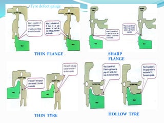
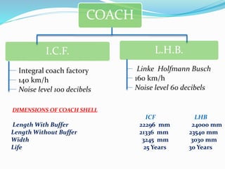
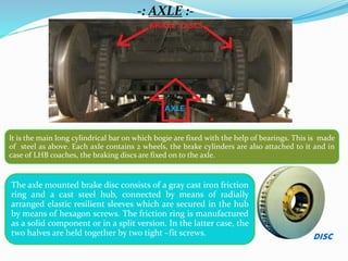
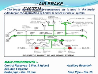
SUBMITTED TO:- SUBMITTED BY:-
Content
 INTRODUCTION
 MAINTENANCE SCHEDULES
 WHEEL PROFILE & DEFECTS
 TYPE OF COACH
 AXLE , BRAKE DISC & BRAKE SHOES
 AIR BRAKE SYSTEM
 BOGIE FRAME
 BODY SHELL & WINDOW UNIT
 WATER TANKS
 CDTS
INDIAN RAILWAY HISTORY
In 1849 GIPR was established by East India Company
First train introduced to India in 1853 between
Boribandar (later VT/CST) in Mumbai to Thane
By 1946 all 42 rail systems taken over by govt. to
make a single nationalized network
INTRODUCTION TO I.R.
 Indian railway is 4th largest railway network having
route length of 64,460 kms.
Over 12,000 trains daily transporting over 9 billion
passengers and over 1050 million tones of freight per
year
World’s largest public sector enterprise with 1.5
million employees
-: INDIAN RAILWAY :-
www.indianrailways.gov.in
First passenger train introduced in India on 16 April 1853 between
Mumbai to Thane (34 km).
Over 10,000 trains daily, transporting over 8,900 million
passengers and over 1050 million tones of freight per year.
Indian Railways is the world's ninth largest organisation, by
number of employees, with over 1.4 million employees.
The number of zones in Indian Railways increased from six to eight
in 1951, nine in 1952 and sixteen in 2003. Presently there are 17
zones & 84 divisions.
As of 31 March 2013, 23,541 km (36%) of the total 65,000 km route
length was electrified.
-: Coach Repair Workshop, Harnaut :-
Foundation stone was laid by A.P.J. Abdul Kalam on June 30,
2003
Site location - Harnaut, Distt- Nalanda (Bihar) ,under ECR
Total Land - 113 Acres (workshop 76 , staff quarters 37)
Year of sanction - 2003-04
Sanctioned Cost - Rs. 224 Cores.
Revised sanctioned Cost - Rs. 337 Cores.
Expenditure - Rs 252.03 Cores. (up to 31.03.13 )
Plant Capacity - POH of 50 coaches per month
Sanctioned staff - 1158
1. Trip schedule- After every trip by primary
maintenance depot.
2. Schedule A - Monthly (1 month )
3. Schedule B - Quarterly (3 months )
4. IOH – 9 months
5. POH – 18 months
-: THE MAINTENANCE SCHEDULES AND THE OVERHAULING PERIODS :-
> POH <
Periodic overhauling is the best available process of maintenance of coaches in India. This
generally operated after 18 months after the manufacturing or the previous periodic
overhauling done in any workshop. This undergoes a huge process of lifting the coach,
isolating the all parts, and changing or replacing the necessary or damaged parts. In other
words this is the process of renewing the coaches.
-It stands for periodic overhauling.
-POH is allowed in nominated workshops only.
-Painting of whole coach is necessary.
-Profiling of wheel is necessary
-: WHEEL PROFILE :-
-: DEFECTS :-
Thin Flange :- When the flange thickness reduces from 28.5 mm to 16 mm or less, then
the flange is called thin flange.
Sharp Flange :- When the radius given at the tip of flange is worn out from 14.5mm
to 5 mm or less is called Sharp Flange.
Thin Tyre :- If the remaining thickness of tyre is less than 25 mm, it is called thin tyre.
Hollow Tyre :- If the groove on the wheel tread is up to 5 mm or more, it is called Hollow tyre
THIN TYRE HOLLOW TYRE
THIN FLANGE SHARP
FLANGE
Tyre defect gauge
COACH
I.C.F. L.H.B.
140 km/h
Integral coach factory Linke Holfmann Busch
160 km/h
DIMENSIONS OF COACH SHELL
ICF LHB
Length With Buffer 22296 mm 24000 mm
Length Without Buffer 21336 mm 23540 mm
Width 3245 mm 3030 mm
Life 25 Years 30 Years
Noise level 60 decibelsNoise level 100 decibels
-: AXLE :-
It is the main long cylindrical bar on which bogie are fixed with the help of bearings. This is made
of steel as above. Each axle contains 2 wheels, the brake cylinders are also attached to it and in
case of LHB coaches, the braking discs are fixed on to the axle.
The axle mounted brake disc consists of a gray cast iron friction
ring and a cast steel hub, connected by means of radially
arranged elastic resilient sleeves which are secured in the hub
by means of hexagon screws. The friction ring is manufactured
as a solid component or in a split version. In the latter case, the
two halves are held together by two tight –fit screws. DISC
-: AIR BRAKE
SYSTEM :- The brake system in which compressed air is used in the brake
cylinder for the application of brakes is called air brake system.
MAIN COMPONENTS :-
Control Reservoir 9 liter, 5 kg/cm2 Auxiliary Reservoir
200 liter, 6 kg/cm2
Brake pipe – Dia. 32 mm Feed Pipe – Dia. 25
 Under normal conditions the Brake pipe is charged with 5kg/cm2 from the
loco. The control reservoir and the Auxiliary reservoir are charged with 5
kg/cm2 and 6 kg/cm2 respectively from BP through Distributor valve.
 When the brake pipe is charged at 5 kg/cm2 the brake cylinder is connected
to exhaust through distributor valve in order to keep the brake in released
position fully.
 Whenever the brake pipe pressure is reduced below the CR pressure, the DV
connects the auxiliary reservoir with the brake cylinder and the air from AR is
sent into the brake cylinder to apply the brake.
 Whenever the brake pipe pressure is equal to CR pressure the DV disconnects
the BC from AR and in turn connects the BC with Exhaust for the release of
brakes fully.
-: Working Principle :-
The different processes involved in working :-
a) Charging
b) Application
c) Release
-: BRAKE SHOE :-
The brake shoe is provided with a brake pad
holder carrying replaceable pads.
The brake shoe consists of the brake pad
holder, the vertical pins and the brake pad.
SHOESDue to BC pressure, the piston moves forward
and strikes against the brake caliper.
The lever arm of the brake caliper presses onto
the disc brake through the brake shoe.
The disc brakes are mounted on the wheel axle
and so rotate along with the wheels.
Due to application of brake shoes, the discs
begin to lose their angular speed.
As a result the axle also begins to slow down
since the two are connected.
Ultimately, the wheels stop rotating as they
are mounted on the same axle.
1.Bogie frame longitudinal component
2. Cross-beam
-: BOGIE FRAME :-
The frame is made up of two
longitudinal components (1)
connected by two cross-beams (2)
which also support the brake units.
The various supports which connect
the different bogie components are
welded to the frame.
shell
Assemblies
Steels used
and their
compositions
UTS
N/mm
2
Yield
Stress
N/mm
2
Side wall,
End wall
and Roof
structure
X2 Cr8 Ferritic Steel
(SS 409M)
( C< .03%, Cr 10-12%,
Si 1%, Mn 1.5%)
450-
600
320
Roof sheet
and Trough
floor
X5 CrNi 18 10
Austenitic Steel (SS
304)
( C< .07%, Cr 18%, Ni
10 % Si 1%, Mn 2%)
700-
850
235
Under frame
IRS M-41 / Corten
Steel
( C < .01%, Cr .35 -
.6%, Ni .2 - .4%
Cu .3 - .6% Si .3 - .7%,
Mn .25%)
440-
480
320
The body shell is of integral light weight
construction consisting of separate
assembly group for under frame, side wall,
roof and end wall. The individual
assemblies are joint to each other by
welding. Three types of steel are used for
manufacture of body shell.
-: BODY SHELL :-
-: WINDOW UNITS :-
The sealed window units consist of 8.4 mm outer glass and
4 mm inner glass with 6 mm Argon gas filled.
 Argon is an inexpensive, non-toxic,
odorless gas .
 It increase sound proofing
characteristics of the window.
 Minimizes heat exchange through
the window.
 Argon will not corrode the window
material.
 This type of windows can even block
ultraviolet rays.
-: Controlled Discharge Toilet System (CDTS) :-
Objective: -The main objective of introducing this type of lavatories
in coaches of Indian Railways to have clean environment around
Railway Track within city limits, station premises and maintenance
sidings. This system works on electro- pneumatic principle where in, the
waste generated from the coach lavatories during run is collected in a
retention tank and is disposed off far away from the city limits on
meeting certain predefined conditions.
-: Working cycle : -
1. On each flushing (Collection):- Simply pressing flush button, starts
the flow of water into the toilet bowl and opens the flapper valve
connecting the toilet bowl to the waste retention tank. At the end of
each flush cycle the wash water stops and the toilet is sealed off from
the retention tank by the flapper valve, which acts as an effective
stench trap, preventing odor from entering in the toilet room.
2. The retention tank discharge valve remains open only for a small
period of time (one minute or less) long enough to completely drain
the retention tank, then closes and remains closed until the required
parameters are again satisfied.
The waste is stored in the retention tank
until the following two parameter are
satisfied.
1) The train should be in acceleration &
running above 30kmph and the number
of flushing should be More than five.
2) Train should be in retardation and
reducing speed of 30kmph irrespective
number of flushes.
Water consumption is only 2.5 liters per flush
cycle for the Indian style toilet Bowl and 1.5
liters for the European style toilet Bowl.
Programmable Logic Controller
(PLC):-
It is the heart of the system. It
senses the speed of the coach and no
of flushes and gets all the
operations done by actuating
corresponding valves.
-:WATER TANKS :-
3 types of water tanks are provided in LHB coach
685 liters: -2 stainless steel water tanks of 685 liters capacity
each. These tanks are installed in under frame are fixed with
frames and are secured by safety belts. These tanks constitute the
fresh water reserves in the passenger coaches. Water level
indicator has been provided in these tanks.
450 liters: -One stainless steel water tanks of 450 liters capacity.
These tanks are installed in under frame, fixed with frames and
is secured by safety belts. This tank installed in the under frame
constitute the fresh water reserves for the generator car.
30 liters:- 3-stainless steel water tanks of 30 liters capacity
installed one in each lavatory in the roof and are
continuously fresh-water-fed by means of pumps. These
tanks are installed alone and are fixed with 2 supports which
are equipped with belts.
BRAKE POWER CERTIFICATE
 The incoming driver shall handover the brake power certificate
to Reliving driver or Deposit it the nominated authority, who
will give it to the outgoing Driver.
 The outgoing driver and guard will satisfy themselves from the
listed coach numbers that the Brake Power Certificate pertains
to their train.
If all of above factors like no hanging parts brakes are
working correctly the temp of axle box is with in
range and the train is in good and safe condition of
running then the train is announced as safe to run.
SAFE TO RUN
SUGGESTION
Shunting should be done earlier then the working time
i.e. before 9am so that complete utilization of
available manpower
Coach should be lifted from both sides during
separation of bogie to avoid damage to centre pivot.
The brake blocks should replaced on bogies as a
set.
ANY QUERY….

Northern railway

  • 1.
  • 2.
    Content  INTRODUCTION  MAINTENANCESCHEDULES  WHEEL PROFILE & DEFECTS  TYPE OF COACH  AXLE , BRAKE DISC & BRAKE SHOES  AIR BRAKE SYSTEM  BOGIE FRAME  BODY SHELL & WINDOW UNIT  WATER TANKS  CDTS
  • 3.
    INDIAN RAILWAY HISTORY In1849 GIPR was established by East India Company First train introduced to India in 1853 between Boribandar (later VT/CST) in Mumbai to Thane By 1946 all 42 rail systems taken over by govt. to make a single nationalized network
  • 4.
    INTRODUCTION TO I.R. Indian railway is 4th largest railway network having route length of 64,460 kms. Over 12,000 trains daily transporting over 9 billion passengers and over 1050 million tones of freight per year World’s largest public sector enterprise with 1.5 million employees
  • 5.
    -: INDIAN RAILWAY:- www.indianrailways.gov.in First passenger train introduced in India on 16 April 1853 between Mumbai to Thane (34 km). Over 10,000 trains daily, transporting over 8,900 million passengers and over 1050 million tones of freight per year. Indian Railways is the world's ninth largest organisation, by number of employees, with over 1.4 million employees. The number of zones in Indian Railways increased from six to eight in 1951, nine in 1952 and sixteen in 2003. Presently there are 17 zones & 84 divisions. As of 31 March 2013, 23,541 km (36%) of the total 65,000 km route length was electrified.
  • 6.
    -: Coach RepairWorkshop, Harnaut :- Foundation stone was laid by A.P.J. Abdul Kalam on June 30, 2003 Site location - Harnaut, Distt- Nalanda (Bihar) ,under ECR Total Land - 113 Acres (workshop 76 , staff quarters 37) Year of sanction - 2003-04 Sanctioned Cost - Rs. 224 Cores. Revised sanctioned Cost - Rs. 337 Cores. Expenditure - Rs 252.03 Cores. (up to 31.03.13 ) Plant Capacity - POH of 50 coaches per month Sanctioned staff - 1158
  • 7.
    1. Trip schedule-After every trip by primary maintenance depot. 2. Schedule A - Monthly (1 month ) 3. Schedule B - Quarterly (3 months ) 4. IOH – 9 months 5. POH – 18 months -: THE MAINTENANCE SCHEDULES AND THE OVERHAULING PERIODS :- > POH < Periodic overhauling is the best available process of maintenance of coaches in India. This generally operated after 18 months after the manufacturing or the previous periodic overhauling done in any workshop. This undergoes a huge process of lifting the coach, isolating the all parts, and changing or replacing the necessary or damaged parts. In other words this is the process of renewing the coaches. -It stands for periodic overhauling. -POH is allowed in nominated workshops only. -Painting of whole coach is necessary. -Profiling of wheel is necessary
  • 8.
    -: WHEEL PROFILE:- -: DEFECTS :- Thin Flange :- When the flange thickness reduces from 28.5 mm to 16 mm or less, then the flange is called thin flange. Sharp Flange :- When the radius given at the tip of flange is worn out from 14.5mm to 5 mm or less is called Sharp Flange. Thin Tyre :- If the remaining thickness of tyre is less than 25 mm, it is called thin tyre. Hollow Tyre :- If the groove on the wheel tread is up to 5 mm or more, it is called Hollow tyre
  • 9.
    THIN TYRE HOLLOWTYRE THIN FLANGE SHARP FLANGE Tyre defect gauge
  • 10.
    COACH I.C.F. L.H.B. 140 km/h Integralcoach factory Linke Holfmann Busch 160 km/h DIMENSIONS OF COACH SHELL ICF LHB Length With Buffer 22296 mm 24000 mm Length Without Buffer 21336 mm 23540 mm Width 3245 mm 3030 mm Life 25 Years 30 Years Noise level 60 decibelsNoise level 100 decibels
  • 11.
    -: AXLE :- Itis the main long cylindrical bar on which bogie are fixed with the help of bearings. This is made of steel as above. Each axle contains 2 wheels, the brake cylinders are also attached to it and in case of LHB coaches, the braking discs are fixed on to the axle. The axle mounted brake disc consists of a gray cast iron friction ring and a cast steel hub, connected by means of radially arranged elastic resilient sleeves which are secured in the hub by means of hexagon screws. The friction ring is manufactured as a solid component or in a split version. In the latter case, the two halves are held together by two tight –fit screws. DISC
  • 12.
    -: AIR BRAKE SYSTEM:- The brake system in which compressed air is used in the brake cylinder for the application of brakes is called air brake system. MAIN COMPONENTS :- Control Reservoir 9 liter, 5 kg/cm2 Auxiliary Reservoir 200 liter, 6 kg/cm2 Brake pipe – Dia. 32 mm Feed Pipe – Dia. 25
  • 13.
     Under normalconditions the Brake pipe is charged with 5kg/cm2 from the loco. The control reservoir and the Auxiliary reservoir are charged with 5 kg/cm2 and 6 kg/cm2 respectively from BP through Distributor valve.  When the brake pipe is charged at 5 kg/cm2 the brake cylinder is connected to exhaust through distributor valve in order to keep the brake in released position fully.  Whenever the brake pipe pressure is reduced below the CR pressure, the DV connects the auxiliary reservoir with the brake cylinder and the air from AR is sent into the brake cylinder to apply the brake.  Whenever the brake pipe pressure is equal to CR pressure the DV disconnects the BC from AR and in turn connects the BC with Exhaust for the release of brakes fully. -: Working Principle :- The different processes involved in working :- a) Charging b) Application c) Release
  • 14.
    -: BRAKE SHOE:- The brake shoe is provided with a brake pad holder carrying replaceable pads. The brake shoe consists of the brake pad holder, the vertical pins and the brake pad. SHOESDue to BC pressure, the piston moves forward and strikes against the brake caliper. The lever arm of the brake caliper presses onto the disc brake through the brake shoe. The disc brakes are mounted on the wheel axle and so rotate along with the wheels. Due to application of brake shoes, the discs begin to lose their angular speed. As a result the axle also begins to slow down since the two are connected. Ultimately, the wheels stop rotating as they are mounted on the same axle.
  • 15.
    1.Bogie frame longitudinalcomponent 2. Cross-beam -: BOGIE FRAME :- The frame is made up of two longitudinal components (1) connected by two cross-beams (2) which also support the brake units. The various supports which connect the different bogie components are welded to the frame.
  • 16.
    shell Assemblies Steels used and their compositions UTS N/mm 2 Yield Stress N/mm 2 Sidewall, End wall and Roof structure X2 Cr8 Ferritic Steel (SS 409M) ( C< .03%, Cr 10-12%, Si 1%, Mn 1.5%) 450- 600 320 Roof sheet and Trough floor X5 CrNi 18 10 Austenitic Steel (SS 304) ( C< .07%, Cr 18%, Ni 10 % Si 1%, Mn 2%) 700- 850 235 Under frame IRS M-41 / Corten Steel ( C < .01%, Cr .35 - .6%, Ni .2 - .4% Cu .3 - .6% Si .3 - .7%, Mn .25%) 440- 480 320 The body shell is of integral light weight construction consisting of separate assembly group for under frame, side wall, roof and end wall. The individual assemblies are joint to each other by welding. Three types of steel are used for manufacture of body shell. -: BODY SHELL :-
  • 17.
    -: WINDOW UNITS:- The sealed window units consist of 8.4 mm outer glass and 4 mm inner glass with 6 mm Argon gas filled.  Argon is an inexpensive, non-toxic, odorless gas .  It increase sound proofing characteristics of the window.  Minimizes heat exchange through the window.  Argon will not corrode the window material.  This type of windows can even block ultraviolet rays.
  • 18.
    -: Controlled DischargeToilet System (CDTS) :- Objective: -The main objective of introducing this type of lavatories in coaches of Indian Railways to have clean environment around Railway Track within city limits, station premises and maintenance sidings. This system works on electro- pneumatic principle where in, the waste generated from the coach lavatories during run is collected in a retention tank and is disposed off far away from the city limits on meeting certain predefined conditions. -: Working cycle : - 1. On each flushing (Collection):- Simply pressing flush button, starts the flow of water into the toilet bowl and opens the flapper valve connecting the toilet bowl to the waste retention tank. At the end of each flush cycle the wash water stops and the toilet is sealed off from the retention tank by the flapper valve, which acts as an effective stench trap, preventing odor from entering in the toilet room. 2. The retention tank discharge valve remains open only for a small period of time (one minute or less) long enough to completely drain the retention tank, then closes and remains closed until the required parameters are again satisfied.
  • 19.
    The waste isstored in the retention tank until the following two parameter are satisfied. 1) The train should be in acceleration & running above 30kmph and the number of flushing should be More than five. 2) Train should be in retardation and reducing speed of 30kmph irrespective number of flushes. Water consumption is only 2.5 liters per flush cycle for the Indian style toilet Bowl and 1.5 liters for the European style toilet Bowl. Programmable Logic Controller (PLC):- It is the heart of the system. It senses the speed of the coach and no of flushes and gets all the operations done by actuating corresponding valves.
  • 20.
    -:WATER TANKS :- 3types of water tanks are provided in LHB coach 685 liters: -2 stainless steel water tanks of 685 liters capacity each. These tanks are installed in under frame are fixed with frames and are secured by safety belts. These tanks constitute the fresh water reserves in the passenger coaches. Water level indicator has been provided in these tanks. 450 liters: -One stainless steel water tanks of 450 liters capacity. These tanks are installed in under frame, fixed with frames and is secured by safety belts. This tank installed in the under frame constitute the fresh water reserves for the generator car. 30 liters:- 3-stainless steel water tanks of 30 liters capacity installed one in each lavatory in the roof and are continuously fresh-water-fed by means of pumps. These tanks are installed alone and are fixed with 2 supports which are equipped with belts.
  • 21.
    BRAKE POWER CERTIFICATE The incoming driver shall handover the brake power certificate to Reliving driver or Deposit it the nominated authority, who will give it to the outgoing Driver.  The outgoing driver and guard will satisfy themselves from the listed coach numbers that the Brake Power Certificate pertains to their train.
  • 22.
    If all ofabove factors like no hanging parts brakes are working correctly the temp of axle box is with in range and the train is in good and safe condition of running then the train is announced as safe to run. SAFE TO RUN
  • 23.
    SUGGESTION Shunting should bedone earlier then the working time i.e. before 9am so that complete utilization of available manpower Coach should be lifted from both sides during separation of bogie to avoid damage to centre pivot. The brake blocks should replaced on bogies as a set.
  • 25.