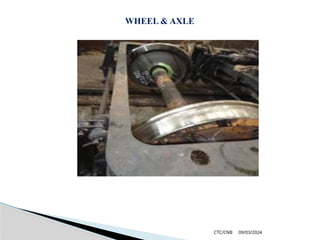
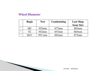
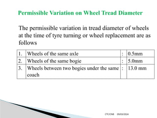
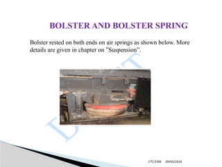
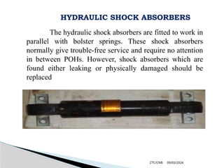
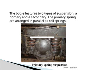
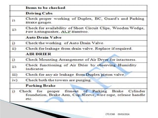
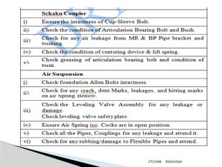
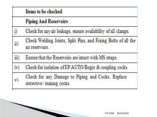
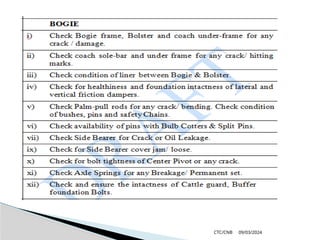
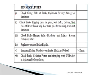
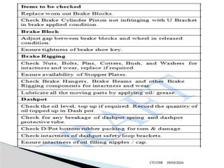
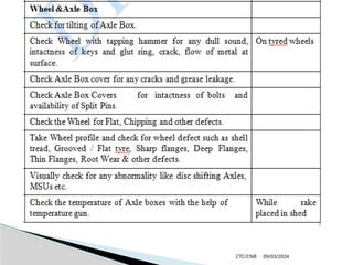
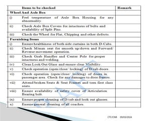
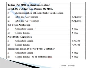
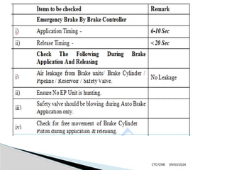
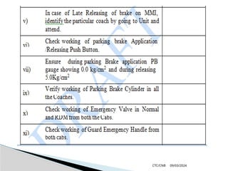
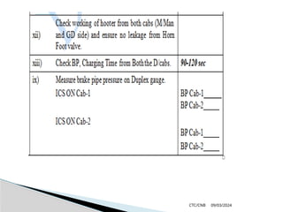
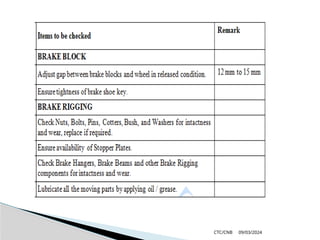
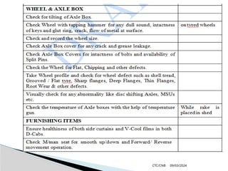
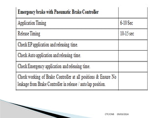
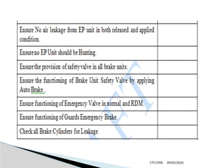
09/03/2024
CTC/CNB
BOGIE & UNDER GEARS
09/03/2024
CTC/CNB
BOGIE FRAME
09/03/2024
CTC/CNB
The bogie frame is a welded construction with two
longitudinal girders and a cross bar and two frame ends.
The tractive or brake force is transmitted via a bogie pin
from the bogie to the body.
The frame ends are used to take up the brake cylinder
and the brake rigging. This vehicle features tread brakes,
which have a direct effect on the wheel.
Furthermore, 4 steel cables are each located between
body and bogie. These are used as a lifting supports.
09/03/2024
CTC/CNB
BOGIE FRAME
09/03/2024
CTC/CNB
Bogies of motor coaches (MC), high
carrying capacity coaches (HCC) and trailer
coaches (TC) are of all welded, light weight
construction. The axles, with self aligning
roller bearings mounted inside cast steel
axle boxes, are rigidly guided by telescopic
dash pot and axle box guide assemblies
09/03/2024
CTC/CNB
Helical springs working in parallel with
dashpots are used for primary suspension. Coach
body is supported on two side bearers located
1700 mm (TC) and 1200 mm (MC & HCC)
apart on a floating bogie bolster which in turn
rests on air spring supported on a spring plank
hung on swing links from bogie frame. The air
springs at each end of bolster are damped by
hydraulic shock absorbers. Side bearers consist
of metal slides immersed in oil baths well
protected from dust ingress
09/03/2024
CTC/CNB
WHEEL & AXLE
09/03/2024
CTC/CNB
The EMU coaches are provided with
composite design of wheels consisting of rolled
steel wheel centres with renewable tyres. The
tyres of TC bogies are fastened to the wheel disc
with glut rings whereas the MC/ HCC bogies
have, in addition to the glut rings, 4 locking keys
to ensure more positive securing.
09/03/2024
CTC/CNB
WHEEL & AXLE
09/03/2024
CTC/CNB
Tyre Profile
09/03/2024
CTC/CNB
Bogie New Condemning Last Shop
Issue Size
1.
MC 952mm 877mm 885mm
2.
TC 952mm 857mm 865mm
3.
HCC 952 mm 865mm 873mm
Wheel Diameter
09/03/2024
CTC/CNB
Permissible Variation on Wheel Tread Diameter
The permissible variation in tread diameter of wheels
at the time of tyre turning or wheel replacement are as
follows
1. Wheels of the same axle : 0.5mm
2. Wheels of the same bogie : 5.0mm
3. Wheels between two bogies under the same
coach
: 13.0 mm
09/03/2024
CTC/CNB
No separate service limits are specified as the
above figures have been fixed to allow for the
differential wear likely to develop between
successive tyre turnings/ wheel changing. It is,
therefore, not necessary to withdraw EMU/MEMU
stock from service specifically for restoring the
differential between wheel diameters to be within the
prescribed limits
09/03/2024
CTC/CNB
ROLLER BEARINGS
MC & HCC Bogies are fitted with direct mounted, double
row, self aligning roller bearings No. 22328 C/C3. TC
Bogies are fitted with direct mounted, double row, self
aligning roller bearing No. 22326 C/C3.
Refer drawing no. EMU/M-0-2-016 (sheet 1 & 2) and
EMU/M-0-0-001 (sheet 1 & 2) for roller bearing of motor
coach, D coach/C coach respectively given in Annexure for
drawings.
09/03/2024
CTC/CNB
AXLE BOX HOUSING
AXLE BOX SPRINGS
Axle box springs are of helical type manufactured from centreless
ground chrome vanadium, silica manganese steel. These springs are
also shot-peened to obtain higher fatigue life. It is necessary to check
these springs for cracks and measure their free height to ensure that
they meet the design requirements.
09/03/2024
CTC/CNB
SUSPENSION
09/03/2024
CTC/CNB
BOLSTER AND BOLSTER SPRING
Bolster rested on both ends on air springs as shown below. More
details are given in chapter on ”Suspension”.
09/03/2024
CTC/CNB
HYDRAULIC SHOCK ABSORBERS
The hydraulic shock absorbers are fitted to work in
parallel with bolster springs. These shock absorbers
normally give trouble-free service and require no attention
in between POHs. However, shock absorbers which are
found either leaking or physically damaged should be
replaced
09/03/2024
CTC/CNB
The bogie features two types of suspension, a
primary and a secondary. The primary spring
are arranged in parallel as coil springs.
Primary spring suspension
09/03/2024
CTC/CNB
AIR SUSPENSION
09/03/2024
CTC/CNB
Each coach having two bogies provided with
16 Nos. of metal bonded conical rubber spring (8 Nos.
per bogie) between the bogie frame and axle box
which acts as a primary suspension system. Each
metal bonded conical rubber spring is subjected to
variable, heavy duty dynamic loading in vertical,
lateral and longitudinal direction during running.
09/03/2024
CTC/CNB
To increase ride comfort, a secondary
spring was fitted. This type of suspension is an air
spring suspension. In the event of a defect
(mechanical damage), this can be disabled via a shut-
off valve. This is located below the body. The bogie
was equipped with an air spring valve. This ensures
that the same body height is maintained independent
of additional load.
09/03/2024
CTC/CNB
Secondary air spring suspension
09/03/2024
CTC/CNB
WORKING PRINCIPLE OF PNEUMATIC (AIR)
SUSPENSION
Air suspension is a suspension where
properties of air are used for cushioning effect
(springiness). Enclosed pressurized air in a pre-
defined chamber called air spring, made up of rubber
bellow & emergency rubber spring, provides various
suspension characteristics including damping
09/03/2024
CTC/CNB
Air springs are height-controlled load
levelling suspension devices. With changing loads, air
spring reacts initially by changing the distance
between air spring support and vehicle body. The
height monitoring valve (called levelling valve) is in
turn actuated, either taking the compressed air
pressure to the air spring or releasing air pressure
from it to the atmosphere. This process continues
until the original height is restored as shown in figure
given below
09/03/2024
CTC/CNB
ADVANTAGES OF AIR SUSPENSION
 Capable to sustain Super Dense Crush Loads typical of suburban
traffic.
 Maintain constant floor height of coach.
 Provide superior ride comfort.
 Virtually constant natural frequency from tare to full loads,
reducing passenger fatigue.
 Isolation of structure borne noise, this improving comfort.
 Improved reliability, reduced maintenance effort.
 Flexibility to choose characteristics as per requirement at design
stage.
09/03/2024
CTC/CNB
AIR SPRING WITH INSIDE EMERGENCY
SPRING
AIR SPRING WITH OUTSIDE EMERGENCY
SPRING
09/03/2024
CTC/CNB
OPERATING & MAINTENANCE
INSTRUCTIONS
09/03/2024
CTC/CNB
Operating Instructions
 Motorman to maintain 7 bar pressure in compressor.
 In case of heavy leakage of air from air spring
system, Isolate the affected bogie and observe speed
restriction at 50 kmph up to the terminal point for
maintenance.
09/03/2024
CTC/CNB
Inspection & Maintenance Of Air Spring
 Inspect for any water collection in rubber bellow
of air spring.
 Inspect the air spring for any damage or leakage.
 Inspect air spring seat and top plates for
corrosion, if corrosion noticed, paint with primer
& black paint
09/03/2024
CTC/CNB
Inspection & Maintenance of Lower Spring Beam
 Inspect all welding joints of the lower spring beam
(cradle) and repair if required.
 Inspect air spring fixing holes of lower spring beam
for elongation, if elongated build them to dia.I3
mm or dia. 22 mm.
 Inspect the corrosion on top surface of lower spring
beam, Remove the corrosion, paint with primer and
black paint.
09/03/2024
CTC/CNB
Test for Leakage
09/03/2024
CTC/CNB
 Connect the hosepipes on the under frame
piping with the leveling valves of the bogies.
 Connect pressure gauges to the drain plug
locations of I50-litre reservoir.
 Provide packing in the gap between bolster &
bogie frame.
 Connect the 150-litre reservoir on the under
frame to the compressed air source of pressure
9.0 kg/cm2
.
Test for Leakage
09/03/2024
CTC/CNB
 Allow air into the air springs to a value of 9.0
kg/cm2
in the pressure gauge by adjusting the
horizontal lever of the leveling valve and keep it in
the same position.
 Close the isolating cock connecting MR pipe with
150 litre reservoir.
 Test all pipe joints for leakages.
Check the pressure gauge readings after one hour.
The pressure drop should be within 1% of the test
pressure 9.0 kg/cm2
.
Release the air completely by dropping the
horizontal lever. Remove the packing.
09/03/2024
CTC/CNB
BRAKE SYSTEM
09/03/2024
CTC/CNB
The vehicle is equipped with several brake
systems. Normally, the joystick/brake lever (Master
Controller) is used for braking the vehicle. This lever
can also be used for a rapid application of the brakes
in the event of an emergency
BRAKING SYSTEM
This system uses the EP brake system. To use
this system in the best possible way, one Brake
Control Unit (BCU) is provided per unit. The BCU
controls the brake force of the units. If the BCU fails,
the TCU will perform the functions of the BCU.
09/03/2024
CTC/CNB
An indirect brake, which can be operated
via two automatic brake valves, serves as a
fallback. One is used by the driver, the second one
by the guard.
The vehicle mainly uses the electric brake.
With this brake, the generated brake force can be
returned back into the contact line network (OHE).
If the brake force cannot be fed into the network,
the brake current is commutated to a brake
resistance and the magnetic drag is reduced to 0 kN
within 1 sec. As a next step, the electro-pneumatic
brake takes over the magnetic drag.
09/03/2024
CTC/CNB
To secure the parked units, a spring-loaded
brake has been installed. It acts on all 4 axles of the
DTC/ NDTC. The brake can be applied or released via
push buttons provided in the driver's cab. In the case of
a fault, the spring-loaded brake is locked by an air shut-
off cock. In this case, the driver has to release the brake
by hand via the emergency release device.
The pneumatic brake is already connected from
15 km/h (due to idle time of the EP brake).
Furthermore, the electronic brake force is reduced
depending on the speed (between 15 to 3 km/h). If the
speed drops below 3km/h, the EP brake is
automatically reduced.
09/03/2024
CTC/CNB
The spring-loaded brake is suitable for
securing the units. It acts on the two bogies of the
DTC / NDTC. Compressed air is required to release
the brake. In the case of a broken or defect hose, the
spring-loaded brake is applied automatically.
However, this fault can be eliminated via the
emergency release device, i.e. one funicular traction
per spring-loaded brake on the bogie. It is no longer
possible to apply the spring-loaded brake after a fault
of this kind. In addition, the shut-off cock of the
spring-loaded brake must always be shut-off for an
emergency release.
09/03/2024
CTC/CNB
09/03/2024
CTC/CNB
BRAKE SYSTEM
09/03/2024
CTC/CNB
BRAKE SYSTEM 2
09/03/2024
CTC/CNB
MAINTENANCE SHEDULES FOR
AC – DC EMU (SIEMENS)
09/03/2024
CTC/CNB
SMI for uniform periodicity of maintenance schedules
for EMU (AC & DC) &MEMU coaches.
The various maintenance schedules periodicity for
AC EMU/MEMU stock as given below should also be
applicable to AC – DC EMU stock plying in Mumbai area.
Due attention to be paid to passenger amenities items
mentioned in para ‘B’ from trip inspection onward.
LEGENDS USED:
TI Trip Inspection
POH 18 months Inspection
IA 45 Days Inspection
IC 180 Days Inspection
09/03/2024
CTC/CNB
TYPE OF SCHEDULE AND PERIODICITY FOR
AC, AC - DC EMU/MEMU
Type of Schedule Periodicity
Daily/ Night -
Trip Inspection (TI) 10 Days
IA 45 Days
6 Monthly (IC) 180 Days
POH 18 Months
09/03/2024
CTC/CNB
CLEANING SCHEUDLE
Washing of exteriors & wet mopping of interiors shall be
done during trip inspection and brooming must be done at night
stabling points every day
ITEMS FOR DAILY CHECKING AT NIGHT STABLING POINT
1. Visual Inspection of wheels for cracks, checking of axle boxes, its
cover and bolts.
2. Check axle guide springs, air springs, bogie frame and all brake
riggings. Also check schaku couplers and side buffers.
3. Check brake blocks for their position and replacements if required.
4. Drain main reservoirs.
5. Check main compressor for their oil level
09/03/2024
CTC/CNB
6. Check gear case suspension housing bolts etc.
7. Check all compartment lights & fans.
8. Check and test horns, wiper, dead man device, guard emergency brake.
9. Check and clean head code, look out glasses.
10. Check fire extinguishers, locking of HT compartment,
driving cabs.
11. Ensure all indications lamps functioning.
09/03/2024
CTC/CNB
12. Formation testing from both the ends and brake testing.
13. Check for all hoses, air pipes.
14. Specially check headlights, taillight and flasher lights.
15. Check for battery voltage.
16. Visual check for any oil leakage from transformer, radiator and pipe lines.
17. Go through the motorman logbook and attend the defects booked during
the run.
18. Record in the logbook any other abnormalities, which need attention in
shed, but ensure safety and reliability.
09/03/2024
CTC/CNB
TRIP INSPECTION SCHEDULE
(10 Days) CARRIAGE
09/03/2024
CTC/CNB
09/03/2024
CTC/CNB
09/03/2024
CTC/CNB
09/03/2024
CTC/CNB
09/03/2024
CTC/CNB
09/03/2024
CTC/CNB
09/03/2024
CTC/CNB
09/03/2024
CTC/CNB
09/03/2024
CTC/CNB
09/03/2024
CTC/CNB
09/03/2024
CTC/CNB
09/03/2024
CTC/CNB
09/03/2024
CTC/CNB
MAINTENANCE SCHEDULE OF
AC-DC (SIEMENS) IA (45 DAYS) CARRIAGE
09/03/2024
CTC/CNB
09/03/2024
CTC/CNB
09/03/2024
CTC/CNB
09/03/2024
CTC/CNB
09/03/2024
CTC/CNB
09/03/2024
CTC/CNB
09/03/2024
CTC/CNB
09/03/2024
CTC/CNB
09/03/2024
CTC/CNB
09/03/2024
CTC/CNB
09/03/2024
CTC/CNB
09/03/2024
CTC/CNB
09/03/2024
CTC/CNB
MAINTENANCE SCHEDULE OF AC-DC
(Siemens) IC (180Days) CARRIAGE
09/03/2024
CTC/CNB
09/03/2024
CTC/CNB
09/03/2024
CTC/CNB
09/03/2024
CTC/CNB
09/03/2024
CTC/CNB
09/03/2024
CTC/CNB
09/03/2024
CTC/CNB
09/03/2024
CTC/CNB
09/03/2024
CTC/CNB
09/03/2024
CTC/CNB
09/03/2024
CTC/CNB
THANKS

mechanical important work guideline MEMU.pptx

  • 1.
  • 2.
  • 3.
    09/03/2024 CTC/CNB The bogie frameis a welded construction with two longitudinal girders and a cross bar and two frame ends. The tractive or brake force is transmitted via a bogie pin from the bogie to the body. The frame ends are used to take up the brake cylinder and the brake rigging. This vehicle features tread brakes, which have a direct effect on the wheel. Furthermore, 4 steel cables are each located between body and bogie. These are used as a lifting supports.
  • 4.
  • 5.
    09/03/2024 CTC/CNB Bogies of motorcoaches (MC), high carrying capacity coaches (HCC) and trailer coaches (TC) are of all welded, light weight construction. The axles, with self aligning roller bearings mounted inside cast steel axle boxes, are rigidly guided by telescopic dash pot and axle box guide assemblies
  • 6.
    09/03/2024 CTC/CNB Helical springs workingin parallel with dashpots are used for primary suspension. Coach body is supported on two side bearers located 1700 mm (TC) and 1200 mm (MC & HCC) apart on a floating bogie bolster which in turn rests on air spring supported on a spring plank hung on swing links from bogie frame. The air springs at each end of bolster are damped by hydraulic shock absorbers. Side bearers consist of metal slides immersed in oil baths well protected from dust ingress
  • 7.
  • 8.
    09/03/2024 CTC/CNB The EMU coachesare provided with composite design of wheels consisting of rolled steel wheel centres with renewable tyres. The tyres of TC bogies are fastened to the wheel disc with glut rings whereas the MC/ HCC bogies have, in addition to the glut rings, 4 locking keys to ensure more positive securing.
  • 9.
  • 10.
  • 11.
    09/03/2024 CTC/CNB Bogie New CondemningLast Shop Issue Size 1. MC 952mm 877mm 885mm 2. TC 952mm 857mm 865mm 3. HCC 952 mm 865mm 873mm Wheel Diameter
  • 12.
    09/03/2024 CTC/CNB Permissible Variation onWheel Tread Diameter The permissible variation in tread diameter of wheels at the time of tyre turning or wheel replacement are as follows 1. Wheels of the same axle : 0.5mm 2. Wheels of the same bogie : 5.0mm 3. Wheels between two bogies under the same coach : 13.0 mm
  • 13.
    09/03/2024 CTC/CNB No separate servicelimits are specified as the above figures have been fixed to allow for the differential wear likely to develop between successive tyre turnings/ wheel changing. It is, therefore, not necessary to withdraw EMU/MEMU stock from service specifically for restoring the differential between wheel diameters to be within the prescribed limits
  • 14.
    09/03/2024 CTC/CNB ROLLER BEARINGS MC &HCC Bogies are fitted with direct mounted, double row, self aligning roller bearings No. 22328 C/C3. TC Bogies are fitted with direct mounted, double row, self aligning roller bearing No. 22326 C/C3. Refer drawing no. EMU/M-0-2-016 (sheet 1 & 2) and EMU/M-0-0-001 (sheet 1 & 2) for roller bearing of motor coach, D coach/C coach respectively given in Annexure for drawings.
  • 15.
    09/03/2024 CTC/CNB AXLE BOX HOUSING AXLEBOX SPRINGS Axle box springs are of helical type manufactured from centreless ground chrome vanadium, silica manganese steel. These springs are also shot-peened to obtain higher fatigue life. It is necessary to check these springs for cracks and measure their free height to ensure that they meet the design requirements.
  • 16.
  • 17.
    09/03/2024 CTC/CNB BOLSTER AND BOLSTERSPRING Bolster rested on both ends on air springs as shown below. More details are given in chapter on ”Suspension”.
  • 18.
    09/03/2024 CTC/CNB HYDRAULIC SHOCK ABSORBERS Thehydraulic shock absorbers are fitted to work in parallel with bolster springs. These shock absorbers normally give trouble-free service and require no attention in between POHs. However, shock absorbers which are found either leaking or physically damaged should be replaced
  • 19.
    09/03/2024 CTC/CNB The bogie featurestwo types of suspension, a primary and a secondary. The primary spring are arranged in parallel as coil springs. Primary spring suspension
  • 20.
  • 21.
    09/03/2024 CTC/CNB Each coach havingtwo bogies provided with 16 Nos. of metal bonded conical rubber spring (8 Nos. per bogie) between the bogie frame and axle box which acts as a primary suspension system. Each metal bonded conical rubber spring is subjected to variable, heavy duty dynamic loading in vertical, lateral and longitudinal direction during running.
  • 22.
    09/03/2024 CTC/CNB To increase ridecomfort, a secondary spring was fitted. This type of suspension is an air spring suspension. In the event of a defect (mechanical damage), this can be disabled via a shut- off valve. This is located below the body. The bogie was equipped with an air spring valve. This ensures that the same body height is maintained independent of additional load.
  • 23.
  • 24.
    09/03/2024 CTC/CNB WORKING PRINCIPLE OFPNEUMATIC (AIR) SUSPENSION Air suspension is a suspension where properties of air are used for cushioning effect (springiness). Enclosed pressurized air in a pre- defined chamber called air spring, made up of rubber bellow & emergency rubber spring, provides various suspension characteristics including damping
  • 25.
    09/03/2024 CTC/CNB Air springs areheight-controlled load levelling suspension devices. With changing loads, air spring reacts initially by changing the distance between air spring support and vehicle body. The height monitoring valve (called levelling valve) is in turn actuated, either taking the compressed air pressure to the air spring or releasing air pressure from it to the atmosphere. This process continues until the original height is restored as shown in figure given below
  • 26.
    09/03/2024 CTC/CNB ADVANTAGES OF AIRSUSPENSION  Capable to sustain Super Dense Crush Loads typical of suburban traffic.  Maintain constant floor height of coach.  Provide superior ride comfort.  Virtually constant natural frequency from tare to full loads, reducing passenger fatigue.  Isolation of structure borne noise, this improving comfort.  Improved reliability, reduced maintenance effort.  Flexibility to choose characteristics as per requirement at design stage.
  • 27.
    09/03/2024 CTC/CNB AIR SPRING WITHINSIDE EMERGENCY SPRING AIR SPRING WITH OUTSIDE EMERGENCY SPRING
  • 28.
  • 29.
    09/03/2024 CTC/CNB Operating Instructions  Motormanto maintain 7 bar pressure in compressor.  In case of heavy leakage of air from air spring system, Isolate the affected bogie and observe speed restriction at 50 kmph up to the terminal point for maintenance.
  • 30.
    09/03/2024 CTC/CNB Inspection & MaintenanceOf Air Spring  Inspect for any water collection in rubber bellow of air spring.  Inspect the air spring for any damage or leakage.  Inspect air spring seat and top plates for corrosion, if corrosion noticed, paint with primer & black paint
  • 31.
    09/03/2024 CTC/CNB Inspection & Maintenanceof Lower Spring Beam  Inspect all welding joints of the lower spring beam (cradle) and repair if required.  Inspect air spring fixing holes of lower spring beam for elongation, if elongated build them to dia.I3 mm or dia. 22 mm.  Inspect the corrosion on top surface of lower spring beam, Remove the corrosion, paint with primer and black paint.
  • 32.
  • 33.
    09/03/2024 CTC/CNB  Connect thehosepipes on the under frame piping with the leveling valves of the bogies.  Connect pressure gauges to the drain plug locations of I50-litre reservoir.  Provide packing in the gap between bolster & bogie frame.  Connect the 150-litre reservoir on the under frame to the compressed air source of pressure 9.0 kg/cm2 . Test for Leakage
  • 34.
    09/03/2024 CTC/CNB  Allow airinto the air springs to a value of 9.0 kg/cm2 in the pressure gauge by adjusting the horizontal lever of the leveling valve and keep it in the same position.  Close the isolating cock connecting MR pipe with 150 litre reservoir.  Test all pipe joints for leakages. Check the pressure gauge readings after one hour. The pressure drop should be within 1% of the test pressure 9.0 kg/cm2 . Release the air completely by dropping the horizontal lever. Remove the packing.
  • 35.
  • 36.
    09/03/2024 CTC/CNB The vehicle isequipped with several brake systems. Normally, the joystick/brake lever (Master Controller) is used for braking the vehicle. This lever can also be used for a rapid application of the brakes in the event of an emergency BRAKING SYSTEM This system uses the EP brake system. To use this system in the best possible way, one Brake Control Unit (BCU) is provided per unit. The BCU controls the brake force of the units. If the BCU fails, the TCU will perform the functions of the BCU.
  • 37.
    09/03/2024 CTC/CNB An indirect brake,which can be operated via two automatic brake valves, serves as a fallback. One is used by the driver, the second one by the guard. The vehicle mainly uses the electric brake. With this brake, the generated brake force can be returned back into the contact line network (OHE). If the brake force cannot be fed into the network, the brake current is commutated to a brake resistance and the magnetic drag is reduced to 0 kN within 1 sec. As a next step, the electro-pneumatic brake takes over the magnetic drag.
  • 38.
    09/03/2024 CTC/CNB To secure theparked units, a spring-loaded brake has been installed. It acts on all 4 axles of the DTC/ NDTC. The brake can be applied or released via push buttons provided in the driver's cab. In the case of a fault, the spring-loaded brake is locked by an air shut- off cock. In this case, the driver has to release the brake by hand via the emergency release device. The pneumatic brake is already connected from 15 km/h (due to idle time of the EP brake). Furthermore, the electronic brake force is reduced depending on the speed (between 15 to 3 km/h). If the speed drops below 3km/h, the EP brake is automatically reduced.
  • 39.
    09/03/2024 CTC/CNB The spring-loaded brakeis suitable for securing the units. It acts on the two bogies of the DTC / NDTC. Compressed air is required to release the brake. In the case of a broken or defect hose, the spring-loaded brake is applied automatically. However, this fault can be eliminated via the emergency release device, i.e. one funicular traction per spring-loaded brake on the bogie. It is no longer possible to apply the spring-loaded brake after a fault of this kind. In addition, the shut-off cock of the spring-loaded brake must always be shut-off for an emergency release.
  • 40.
  • 41.
  • 42.
  • 43.
  • 44.
    09/03/2024 CTC/CNB SMI for uniformperiodicity of maintenance schedules for EMU (AC & DC) &MEMU coaches. The various maintenance schedules periodicity for AC EMU/MEMU stock as given below should also be applicable to AC – DC EMU stock plying in Mumbai area. Due attention to be paid to passenger amenities items mentioned in para ‘B’ from trip inspection onward. LEGENDS USED: TI Trip Inspection POH 18 months Inspection IA 45 Days Inspection IC 180 Days Inspection
  • 45.
    09/03/2024 CTC/CNB TYPE OF SCHEDULEAND PERIODICITY FOR AC, AC - DC EMU/MEMU Type of Schedule Periodicity Daily/ Night - Trip Inspection (TI) 10 Days IA 45 Days 6 Monthly (IC) 180 Days POH 18 Months
  • 46.
    09/03/2024 CTC/CNB CLEANING SCHEUDLE Washing ofexteriors & wet mopping of interiors shall be done during trip inspection and brooming must be done at night stabling points every day ITEMS FOR DAILY CHECKING AT NIGHT STABLING POINT 1. Visual Inspection of wheels for cracks, checking of axle boxes, its cover and bolts. 2. Check axle guide springs, air springs, bogie frame and all brake riggings. Also check schaku couplers and side buffers. 3. Check brake blocks for their position and replacements if required. 4. Drain main reservoirs. 5. Check main compressor for their oil level
  • 47.
    09/03/2024 CTC/CNB 6. Check gearcase suspension housing bolts etc. 7. Check all compartment lights & fans. 8. Check and test horns, wiper, dead man device, guard emergency brake. 9. Check and clean head code, look out glasses. 10. Check fire extinguishers, locking of HT compartment, driving cabs. 11. Ensure all indications lamps functioning.
  • 48.
    09/03/2024 CTC/CNB 12. Formation testingfrom both the ends and brake testing. 13. Check for all hoses, air pipes. 14. Specially check headlights, taillight and flasher lights. 15. Check for battery voltage. 16. Visual check for any oil leakage from transformer, radiator and pipe lines. 17. Go through the motorman logbook and attend the defects booked during the run. 18. Record in the logbook any other abnormalities, which need attention in shed, but ensure safety and reliability.
  • 49.
  • 50.
  • 51.
  • 52.
  • 53.
  • 54.
  • 55.
  • 56.
  • 57.
  • 58.
  • 59.
  • 60.
  • 61.
  • 62.
    09/03/2024 CTC/CNB MAINTENANCE SCHEDULE OF AC-DC(SIEMENS) IA (45 DAYS) CARRIAGE
  • 63.
  • 64.
  • 65.
  • 66.
  • 67.
  • 68.
  • 69.
  • 70.
  • 71.
  • 72.
  • 73.
  • 74.
  • 75.
    09/03/2024 CTC/CNB MAINTENANCE SCHEDULE OFAC-DC (Siemens) IC (180Days) CARRIAGE
  • 76.
  • 77.
  • 78.
  • 79.
  • 80.
  • 81.
  • 82.
  • 83.
  • 84.
  • 85.
  • 86.