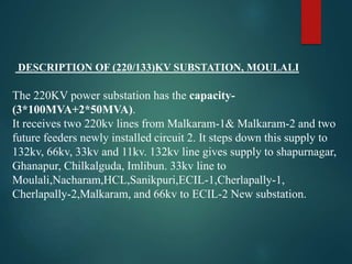
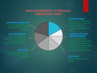
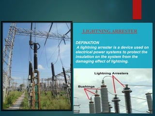
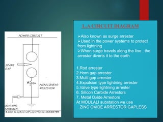
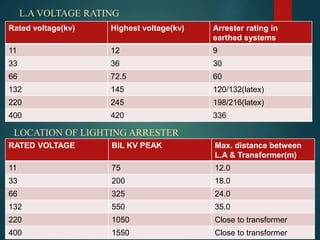
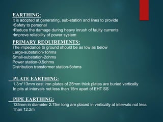
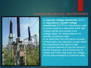
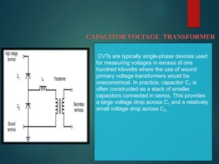
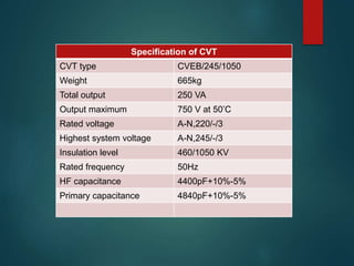
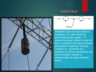
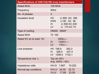
Decoding Kotlin - Your guide to solving the mysterious in Kotlin.pptx
ELECTRIC SUB-STATION IN BRIEF
1. MAINTENANCE & PROTECTION OF
SUBSTATION (220/133)KV-MOULALI
SUBMITTED BY:
J. ARAVIND KUMAR 13BK1A0217
2. DESCRIPTION OF (220/133)KV SUBSTATION, MOULALI
The 220KV power substation has the capacity-
(3*100MVA+2*50MVA).
It receives two 220kv lines from Malkaram-1& Malkaram-2 and two
future feeders newly installed circuit 2. It steps down this supply to
132kv, 66kv, 33kv and 11kv. 132kv line gives supply to shapurnagar,
Ghanapur, Chilkalguda, Imlibun. 33kv line to
Moulali,Nacharam,HCL,Sanikpuri,ECIL-1,Cherlapally-1,
Cherlapally-2,Malkaram, and 66kv to ECIL-2 New substation.
4. TRANSFORMERS
Also known as the heart
of substations. These are
used to reduce the
voltages at appropriate
levels
CURRENT VOLTAGE
TRANSFORMERS
It is a used in power
systems to step downextra
high voltage signals and
provide a low voltage signal,
for measurement or to
operate a protective relay
WAVETRAP
Traps the high frequency
signals
ISOLATORS
Used for maintenance of
the circuit in no load
condition
CIRCUIT BREAKER
used to protect the
eqiupment by opening
the circuit for over
current and over voltages
LIGHTINING ARRESTER
Used for protecting the
equipment from surge
voltages
MAIN EQUIPMENTS AT MOULALI
SUBSTATION 220KV
5. LIGHTNING ARRESTER
DEFINATION
A lightning arrester is a device used on
electrical power systems to protect the
insulation on the system from the
damaging effect of lightning.
6. L.A CIRCUIT DIAGRAM
1.Rod arrester
2.Horn gap arrester
3.Multi gap arrester
4.Expulsion type lightning arrester
5.Valve type lightning arrester
6. Silicon Carbide Arrestors
7. Metal Oxide Arrestors
At MOULALI substation we use
ZINC OXIDE ARRESTOR GAPLESS
Also known as surge arrester
Used in the power systems to protect
from lightning
When surge travels along the line , the
arrestor diverts it to the earth
7. Rated voltage(kv) Highest voltage(kv) Arrester rating in
earthed systems
11 12 9
33 36 30
66 72.5 60
132 145 120/132(latex)
220 245 198/216(latex)
400 420 336
L.A VOLTAGE RATING
LOCATION OF LIGHTING ARRESTER
RATED VOLTAGE BIL KV PEAK Max. distance between
L.A & Transformer(m)
11 75 12.0
33 200 18.0
66 325 24.0
132 550 35.0
220 1050 Close to transformer
400 1550 Close to transformer
8. EARTHING:
It is adopted at generating, sub-station and lines to provide
•Safety to personal
•Reduce the damage during heavy inrush of faulty currents
•Improve reliability of power system
PRIMARY REQUIREMENTS:
The impedance to ground should be as low as below
Large-substation-1ohms
Small-substation-2ohms
Power station-0.5ohms
Distribution transformer station-5ohms
PLATE EARTHING:
1.3m*13mm cast iron plates of 25mm thick plates are buried vertically
In pits at intervals not less than 15m apart of EHT SS
PIPE EARTHING:
125mm in diameter 2.75m long are placed in vertically at intervals not less
Than 12.2m
9. CAPACITOR VOLTAGE TRANSFORMER
A capacitor voltage transformer (CVT),
or capacitance coupled voltage
transformer (CCVT) is a transformer used
in power systems to step down extra high
voltage signals and provide a low
voltage signal, for measurement or to
operate a protective relay.
In its most basic form the device consists
of three parts: two capacitors across which
the transmission line signal is split,
an inductive element to tune the device to
the line frequency, and a transformer to
isolate and further step down the voltage
for the instrumentation or protective relay.
10. CAPACITOR VOLTAGE TRANSFORMER
CVTs are typically single-phase devices used
for measuring voltages in excess of one
hundred kilovolts where the use of wound
primary voltage transformers would be
uneconomical. In practice, capacitor C1 is
often constructed as a stack of smaller
capacitors connected in series. This provides
a large voltage drop across C1 and a relatively
small voltage drop across C2.
11. Specification of CVT
CVT type CVEB/245/1050
Weight 665kg
Total output 250 VA
Output maximum 750 V at 50’C
Rated voltage A-N,220/-/3
Highest system voltage A-N,245/-/3
Insulation level 460/1050 KV
Rated frequency 50Hz
HF capacitance 4400pF+10%-5%
Primary capacitance 4840pF+10%-5%
12. WAVE TRAP
Reliable & fast communication is
necessary for safe efficient &
economical power supply . To
reduce the power failure in extent &
time, to maintain the interconnected
grid system in optimum working
condition to coordinate the
operation of various generating unit
communication network is
indispensable for state electricity
board.
13. Wave trap
Wave trap is an instrument using for trapping
of the wave. The function of this trap is that it
traps the unwanted waves. Its function is of
trapping wave. Its shape is like a drum. It is
connected to the main incoming feeder so
that it can trap the waves which may be
dangerous to the instruments here in the
substation. Low pass filter when power
frequency currents are passed to switch yard
and high frequency signals are blocked.
It is used for communication purpose.
14. ISOLATOR
Isolator
Used to ensure that an electrical circuit is
completely de-energised for service or
maintenance. Such switches are often
found in electrical
distribution and industrial applications,
where machinery must have its source of
driving power removed for adjustment or
repair. High-voltage isolation switches are
used in electrical substations to allow
isolation of apparatus such as circuit
breakers, transformers, and transmission
lines, for maintenance. It is only for safety
isolation. Disconnector can be operated
either manually or automatically (motorized
disconnector)
15. STEPS OF OPERATION OF ISOLATOR
SEQUENCE OF STEPS FOR ATTENDING
MAINTENANCE:
1. Open CB on no load or full load
2. Open the isolator on no load
3. Close the earth switch
SEQUENCE OF STEPS FOR KEPT IN
SERVICE
1. Open the earth switch
2. Close the isolator
3. Close the CB
16. INSTRUMENTS TRANSFORMERS
“Instrument transformers in which the secondary current or voltage is
substantially proportional to primary current or voltage and differs in
phase form it by an angle which is approximately zero for an appropriate
direction of connection”.
They convert higher line voltages or line currents into proportionally
reduced values by means of Electromagnetic circuit.
Protects the instruments and system by measuring abnormalities and
Signal to relay to isolate the faulty system.
There are two types of this they are,
Current transformers
Voltage transformers
17. Current transformer
Current transformer is a current measuring device used to measure
the currents in high voltage lines directly by stepping down the
currents to measurable values by means of electromagnetic circuit.
Basic design principle of a CT:
Primary ampere turns = Secondary ampere turns
Ip*Np = Is*Ns
Where , Ip-primary current
Np-primary winding turns
Is- secondary current,
Ns-secondary winding turns
Ampere turns play very important role in designing CT.
CT must be connected in series only.
CT has more no. of turns in secondary winding than the first.
Secondary current is directly proportional to primary current
18. Tests generally to be conducted on CT:
Ratio test: primary injection test is to be conducted for this purpose
TAN-DELTA test: on 132KV CTs and above
Polarity test at the time of commissioning
Excitation characteristics check
Secondary and lead resistance check
Secondary injection test
Primary injection test
The accuracy of CT is directly related to a factors as,
Burden
Burden class/saturation class
Rating factor
Load
External electromagnetic fields
Temperature
Physical configuration
19. Potential transformer (PT):
An instrument transformer in which the secondary voltage, in normal conditions
Of use, is substantially proportional o the primary voltage and differs in phase
From it by an angle which is approximately zero for an appropriate direction
Of the connections
Basic functions of PT;
To reduce the line voltage to a value which is suitable for standard
measuring instruments relays etc.
To isolate the measuring instruments, meters, relays etc. from high voltage
side an instillation
To sense abnormalities in voltage and give signals to protective relays to
isolate the defective system.
Basic design principle involved in PT:
voltage ratio = turns ratio
Vp/Vs = Np/Vs
20. Tests generally to conducted on PT:
Insulation resistance values(IR values)
Ratio tests
Polarity tests
GENERAL CHECKS FOR PT:
Mechanical alignments for PT power jaws
PT primary winding star earthing
Tightness of all connections
Primary/secondary fuse rating
PT specifications
21. CIRCUIT BREAKER
A circuit breaker is equipment, which can open
or close a circuit under normal as well as fault
condition. These circuit breaker breaks for a
fault which can damage other instrument in the
station. It is so designed that it can be operated
manually (or by remote control) under normal
conditions and automatically under fault
condition. Whenever a fault occurs trip coil gets
energized, the moving contacts are pulled by
some mechanism & therefore the circuit is
opened or circuit breaks.
22. CIRCUIT BREAKER
1. Actuator mechanism - forces the
contacts together or apart
2. Contacts - Allow current when
touching and break the current
when moved apart
3. Terminals
4. Bimetallic strip.
5. Calibration screw - allows the
manufacturer to precisely adjust
the trip current of the device after
assembly.
6. Solenoid
7. Arc divider/extinguisher
23. Sulphur hexafluoride
circuit breaker (SF6)
Sulphur hexa fluoride (SF6)
gas is used as the arc
quenching medium . The
SF6 is an electronegative
gas and has a strong
tendency to absorb free
electrons. Circuit breakers
have been developed for
voltage 115KV to 230KV ,
power rating10 MVA
Vacuum circuit breakers
are circuit breakers which
are used to protect
medium and high voltage
circuits from dangerous
electrical situations
Air-blast circuit breaker
Fast operations ,suitability for repeated
operation , auto reclosure , unit type
multi break constructions ,simple
assembly , modest maintenance are
some of the main features of air blast
circuit breakers. A compressors plant
necessary to maintain high air
pressure in the air receiver.
Oil circuit breaker
A high-voltage circuit
breaker in which the
arc is drawn in oil to
dissipate the heat
and extinguish the
arc; the intense heat
of the arc
decomposes the oil .
DIFFERENT CIRCUIT BREAKERS
25. TRANSFORMERS
POWER TRANSFORMERS
Transformer is a static machine, which transforms the
potential of alternating current at same frequency. It
means the transformer transforms the low voltage into
high voltage & high voltage to low voltage at same
frequency. It works on the principle of mutual
inductance.
When the energy is transformed to a higher voltage, the
transformer is called step up transformer and then it is
transmitted at lower voltage it is called step down
transformer.
There are 3 transformers in the substation:
100MVA, 220/132 KV (3nos.)
100 MVA (2nos)
26. Power Transformer feeding
160 MVA transformers are manufactured by
ADITYA and by TRM. These are the power
transformers and , there efficiency is high. Primary
side is star connected while secondary is delta
connected.
There are seventeen tapping in it.
Every transformer has OLTC to change the tap for
controlling voltage.
TYPES OF COOLING:
AIR NATURAL COOLING
AIR BLAST COOLING
OIL NATURAL COOLING
OIL BLAST COOLING etc.
27. Specifications of 220/132(100 mva) trasnformers
Rated MVA 100 MVA
Frequency 50Hz
No. of phases 3
Insulation level HV LI 900 AC 395
HVN LI 95 AC 38
IV LI 550 AC 230
LV LI 170 AC 70
Type of cooling ONAN DNAF
Rated MVA 75 100
Rated KV at no load: HV 220kv—
IV 132KV—
LV 11KV—
Line amperes HV 196.8 262.2
IV 328.0 437.4
LV 1299.0 1732.1
Temperature rise ‘c Top oil--50’c
Avg .WDG—55’c
Impedance volts HV-IV 7.667 10.222
Normal tap conditions HV-LV 24.55 32.72
IV-LV 17.69 23.59
28. Capacitor Banks
In simple terms capacitor banks
are collection of capacitor
connected together in series or
parallel depending upon
requirement.