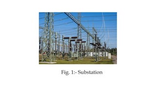
DEPARTMENT OF ELECTRICAL ENGINNERING
A SUMMER TRAINING REPORT
AT
“220 KV GSS RRVPN KOTPUTLI(JAIPUR)”
Submitted To :- Submitted By :-
DK PALWALIA SIR SNEHA KANWAR
Assistant Professor 20/253
5th Sem.
S. No. Name Page No.
1. Single line diagram of 220 KV GSS Kotputli(Jaipur) 3-4
2. Details of EHV Transformer installed at 220 KV GSS Kotputli(Jaipur) 5
3. Substation 6-45
4. Conclusion 46

INCOMING FEEDER
1. 220 KV HEERAPURA LINE
2. 220 KV MANOHARPURA LINE
3. 220 KV NEEMRANA LINE
4. 220 KV BANSUR LINE
5. 220 KV PGCIL-KHELNA LINE
OUTGOING FEEDER
1. 132 KV KESHWANA LINE
2. 132 KV BANSUR LINE
3. 132 KV PAOTA LINE
4. 132 KV GRASIM LINE
5. 33 KV BADABAS
6. 33 KV PATHREDI
7. 33 KV PUTLI
S. No. Voltage Level in KV Capacity in MVA Make
1. 220/132 100 TELK
2. 220/132 100 BHEL
3. 132/33 20/25 IMP
4. 132/33 40/50 T&R
5. 132/33 40/50 IMP
DETAILS OF EHV TRANSFORMERS INSTALLED AT 220 KV
GSS KOTPUTLI(JAIPUR)
Sub-station is a subsidiary station of an electric generation ,transmission and
distribution system where voltage is transformed from high to low or low to high
voltage using transformers.
Electric Power may flow through several sub- station between generated plant and
consumer and may be changed in voltage in several steps.
Substation is used for metering.
Substation also improves the power quality.
Substation
Fig. 1:- Substation
Substation
Panel section
Control panel
section
Relay and
protection
panel section
Switch yard
1. 220KV
2.132KV
3. 33KV
 It is a room which contains all types of panels.
 It has two sections:-
1. Control Panel Section
It contain panels related to controlling of instruments.
E.g.:- Feeder panel, Transformer panel, etc.
2. Relay And Protection Panel Section
It contains panels related to relay systems and protection systems.
E.g.:- Relay panel, line protection panel, etc.
Panel section
Fig. 2 :-Panel Section
It is the field where components used in controlling supply and measuring
supply(incoming and outgoing) are placed.
Some of these components are:-
1. Circuit breaker
2. Isolators
3. Current transformer
4. Potential transformer
5. Lightning arrester
6. Transformer , etc.
Switch yard
Fig. 3 :- Switch yard
 Lightning arrester
 Isolators
 Circuit breaker
 Wave trapper
 Bus bar
 Power transformer
 Instrument transformer
 Current transformer
 Potential transformer
 Relay
 Insulator
 Capacitor bank
 Power line Carrier current capacitor
Component of substation
 A lightning arrester is a device used on electrical power
systems and telecommunications systems to protect the
insulation and conductors of the system from damaging the
effects of lightning.
 The typical lightning arrester has a high voltage terminal
and a ground terminal.
 It located at the starting of the substation as seen from
incoming transmission lines and is the first equipment of
substation.
Lightning arrester
Fig. 4 :-Lightning arrester
 Isolator is a mechanical switch which isolates a part of
circuit from system as when required.
 The use of isolator is to off the transformer and the
other instrument in the line.
 Isolators are used for maintenance whenever fault
occur.
 It is manually operated.
Isolators
Fig. 5 :-Isolator
Isolator
Double break
isolator
Single break
isolator
Pantograph
type isolator
 A circuit breaker is a switch which work is to
make or break a circuit manually or
automatically under abnormal condition.
 It is designed to protect an electrical circuit
from damage caused by overload or short
circuit .
 Its basic function is to detect a fault condition
and discontinue the electric flow.
Circuit breaker
Fig. 6 :-Circuit Breaker
Type of circuit breaker
•Oil circuit breaker
•Air blast circuit breaker
•SF6 circuit breaker
•Vacuum circuit breaker
THE MAIN FUNCTION OF CIRCUIT BREAKER
•It carries current continuously without heating.
• Opens or close the circuit when required.
•It protects the circuit incase of any fault.
 Wave trap is a device used in the substation at the incoming line
 Wave trap is also called as line trap.
 The wave trap extracts the high frequency information from the power line and
route it to the telecomm panels.
On the basis of blocking frequency bank, the wave trap can be following type:
1. ALL WAVE
2. SINGAL FREQUENCY
3. DOUBLE FREQUENCY
4. BROAD BAND
Wave trapper
Fig. 7 :-Wave trap
 Bus Bars are the common electrical component through which a large no of
feeders operating at same voltage have to be connected.
 A bus bar is a conducting bar that carries heavy currents to supply several
electric circuits.
 Made up of copper rod or thin walled tubes.
Bus Bar
Fig. 8 :-Busbar
• To step-up or step-down the voltage and transfer power from one a.c. voltage to
another a.c. voltage at the same frequency.
• A Static Device.
• Transfer Power from one circuit to Another circuit.
• No Change in frequency.
• Principle-Faraday’s law of electromagnetic induction.
• Types-
1. STEP UP X-MER :
O/P Voltage > I/P Voltage.
2. STEP DOWN X-MER ::
O/P Voltage < I/P Voltage.
Power transformer
Fig. 9 :-Power transformer
 Core
 Winding(H.V winding, L.V winding, tertiary winding)
 X-MER OILS
 PRESSURE RELIEF VALVE
 BREATHER
 Conservator
 RADIATER
 Tap changer
 Tank
PARTS OF TRANSFORMER
 Instrument transformers are used for measurement and protective applications
together with equipments such as meters & relays.
Instrument transformer
Instrument
transformer
Current
transformer
Potential
transformer
Fig. 10:- Instrument transformer
 Current transformer is a type of instrument transformer that is used in power
system for measurement, detection, protection of the system.
 When current in a circuit is too high to apply directly measuring instruments, a
CT produces a reduced current accurately proportional to the current in the
circuit, which can be conveniently connected to measuring and recording
instruments.
Current transformer
Fig.11 :- Current transformer
 Potential transformers are instrument transformers. They have a large number
of primary turns and a few number of secondary turns.
 It step down the voltage to something that meters can handle.
Potential transformer
Fig.12 :- Potential transformer
 Relay are switches that open and close circuits electromechanically. They control
one electrical circuit by opening and closing contacts in another circuit.
 It trips the circuit breaker when fault is detected
 Types of relay :-
Over voltage relays
Over current relays
I.D.M.T. Relay
Direction relay
Differential relay
Buchholz ’s relay
Relay
Fig.13 :-Relay
 A relay that has contacts that operate when a set voltage is exceeded to provide an
alarm or to trigger a breaker.
 Over current relay is a type of protective relay which operates when the load current
exceeds a pickup value.
 IDMT relay is inverse definite minimum time relay. It is one in which Time of
operation is inversely proportional to magnitude of fault current near pickup value
and becomes substantially constant slightly above the pickup value of the Relay.
Over Voltage Relay
Over current Relay
IDMT Relay
 Directional over current relays respond to excessive current flow in a particular
direction in the power system. It is used for protection in d-c power circuits.
 The differential relay is one that operates when there is a difference between two
or more similar electrical quantities exceeds a predetermined value.
 Buchholz relay is a safety device mounted on some oil-filled
power transformer and reactors, equipped with an external overhead oil reservoir
called a "conservator".
Directional relay :
Differential relay:
Buchholz ’s relay:
 An insulator also called a dielectric, is a material that resists the flow of electric
current. Insulators are used in electrical equipment to support and separate electrical
conductors without allowing current through themselves.
 Types of insulators:-
1. Pin type
2. Suspension type
3. Strain type
4. Shackle type
5. Stay type
Insulator
Fig.14 :- Insulator
 A capacitor bank is used for reactive power compensation and power factor
correction in the power substations.
 The capacitor bank is connected in two ways – star and delta.
 The capacitor bank used in substation for the following reasons.
1.It will improve and correct the power factor.
2.It will control the level of supply voltage.
3.It will improve the power handling capacity of substation.
Capacitor bank
Fig.15 :- Capacitor bank
 Power line communication carries data on conductor that is also used
simultaneously for AC electric power transmission or electric power distribution to
consumers.
 The PLCC can be used for the following facilities:
1.Telephony
2.Teleprotection
3.Remote control or indication
4.Telemetry
5.Teleprinting
Power line carrier communication
Fig.16 :- Power line carrier communication
TRANSFORMERS Also
known as the heart of
substations. These are
used to reduce the
voltages at appropriate
level
CURRENT VOLTAGE
TRANSFORMERS It is
a used in power systems
to step down extra high
voltage signals and
provide a low voltage
signal, for measurement
or to operate a
protective relay
WAVETRAP Traps the
high frequency signals
RELAY Used to sense
the faults
ISOLATORS Used for
maintenance of the
circuit in no load
condition
CIRCUIT BREAKER
used to protect the
equipment by opening
the circuit for over
current and over
voltages
LIGHTINING
ARRESTER Used for
protecting the
equipment from surge
voltages
SUMMARY OF EQUIPMENTs
 Now from this report we can conclude that electricity plays an important role in our life.
We are made aware of how the transmission of electricity is done. We too came to know
about the various parts of the Substation system as well as the grid and its
interconnections.
Conclusion
THANK YOU ‼
ANY QUERY ?

Indusrtrial training ppt (1).pptx

  • 1.
    DEPARTMENT OF ELECTRICALENGINNERING A SUMMER TRAINING REPORT AT “220 KV GSS RRVPN KOTPUTLI(JAIPUR)” Submitted To :- Submitted By :- DK PALWALIA SIR SNEHA KANWAR Assistant Professor 20/253 5th Sem.
  • 2.
    S. No. NamePage No. 1. Single line diagram of 220 KV GSS Kotputli(Jaipur) 3-4 2. Details of EHV Transformer installed at 220 KV GSS Kotputli(Jaipur) 5 3. Substation 6-45 4. Conclusion 46
  • 3.
  • 4.
    INCOMING FEEDER 1. 220KV HEERAPURA LINE 2. 220 KV MANOHARPURA LINE 3. 220 KV NEEMRANA LINE 4. 220 KV BANSUR LINE 5. 220 KV PGCIL-KHELNA LINE OUTGOING FEEDER 1. 132 KV KESHWANA LINE 2. 132 KV BANSUR LINE 3. 132 KV PAOTA LINE 4. 132 KV GRASIM LINE 5. 33 KV BADABAS 6. 33 KV PATHREDI 7. 33 KV PUTLI
  • 5.
    S. No. VoltageLevel in KV Capacity in MVA Make 1. 220/132 100 TELK 2. 220/132 100 BHEL 3. 132/33 20/25 IMP 4. 132/33 40/50 T&R 5. 132/33 40/50 IMP DETAILS OF EHV TRANSFORMERS INSTALLED AT 220 KV GSS KOTPUTLI(JAIPUR)
  • 6.
    Sub-station is asubsidiary station of an electric generation ,transmission and distribution system where voltage is transformed from high to low or low to high voltage using transformers. Electric Power may flow through several sub- station between generated plant and consumer and may be changed in voltage in several steps. Substation is used for metering. Substation also improves the power quality. Substation
  • 7.
  • 8.
    Substation Panel section Control panel section Relayand protection panel section Switch yard 1. 220KV 2.132KV 3. 33KV
  • 9.
     It isa room which contains all types of panels.  It has two sections:- 1. Control Panel Section It contain panels related to controlling of instruments. E.g.:- Feeder panel, Transformer panel, etc. 2. Relay And Protection Panel Section It contains panels related to relay systems and protection systems. E.g.:- Relay panel, line protection panel, etc. Panel section
  • 10.
  • 11.
    It is thefield where components used in controlling supply and measuring supply(incoming and outgoing) are placed. Some of these components are:- 1. Circuit breaker 2. Isolators 3. Current transformer 4. Potential transformer 5. Lightning arrester 6. Transformer , etc. Switch yard
  • 12.
    Fig. 3 :-Switch yard
  • 13.
     Lightning arrester Isolators  Circuit breaker  Wave trapper  Bus bar  Power transformer  Instrument transformer  Current transformer  Potential transformer  Relay  Insulator  Capacitor bank  Power line Carrier current capacitor Component of substation
  • 14.
     A lightningarrester is a device used on electrical power systems and telecommunications systems to protect the insulation and conductors of the system from damaging the effects of lightning.  The typical lightning arrester has a high voltage terminal and a ground terminal.  It located at the starting of the substation as seen from incoming transmission lines and is the first equipment of substation. Lightning arrester
  • 15.
  • 16.
     Isolator isa mechanical switch which isolates a part of circuit from system as when required.  The use of isolator is to off the transformer and the other instrument in the line.  Isolators are used for maintenance whenever fault occur.  It is manually operated. Isolators
  • 17.
  • 18.
  • 19.
     A circuitbreaker is a switch which work is to make or break a circuit manually or automatically under abnormal condition.  It is designed to protect an electrical circuit from damage caused by overload or short circuit .  Its basic function is to detect a fault condition and discontinue the electric flow. Circuit breaker
  • 20.
  • 21.
    Type of circuitbreaker •Oil circuit breaker •Air blast circuit breaker •SF6 circuit breaker •Vacuum circuit breaker THE MAIN FUNCTION OF CIRCUIT BREAKER •It carries current continuously without heating. • Opens or close the circuit when required. •It protects the circuit incase of any fault.
  • 22.
     Wave trapis a device used in the substation at the incoming line  Wave trap is also called as line trap.  The wave trap extracts the high frequency information from the power line and route it to the telecomm panels. On the basis of blocking frequency bank, the wave trap can be following type: 1. ALL WAVE 2. SINGAL FREQUENCY 3. DOUBLE FREQUENCY 4. BROAD BAND Wave trapper
  • 23.
  • 24.
     Bus Barsare the common electrical component through which a large no of feeders operating at same voltage have to be connected.  A bus bar is a conducting bar that carries heavy currents to supply several electric circuits.  Made up of copper rod or thin walled tubes. Bus Bar
  • 25.
  • 26.
    • To step-upor step-down the voltage and transfer power from one a.c. voltage to another a.c. voltage at the same frequency. • A Static Device. • Transfer Power from one circuit to Another circuit. • No Change in frequency. • Principle-Faraday’s law of electromagnetic induction. • Types- 1. STEP UP X-MER : O/P Voltage > I/P Voltage. 2. STEP DOWN X-MER :: O/P Voltage < I/P Voltage. Power transformer
  • 27.
    Fig. 9 :-Powertransformer
  • 28.
     Core  Winding(H.Vwinding, L.V winding, tertiary winding)  X-MER OILS  PRESSURE RELIEF VALVE  BREATHER  Conservator  RADIATER  Tap changer  Tank PARTS OF TRANSFORMER
  • 29.
     Instrument transformersare used for measurement and protective applications together with equipments such as meters & relays. Instrument transformer Instrument transformer Current transformer Potential transformer
  • 30.
  • 31.
     Current transformeris a type of instrument transformer that is used in power system for measurement, detection, protection of the system.  When current in a circuit is too high to apply directly measuring instruments, a CT produces a reduced current accurately proportional to the current in the circuit, which can be conveniently connected to measuring and recording instruments. Current transformer
  • 32.
    Fig.11 :- Currenttransformer
  • 33.
     Potential transformersare instrument transformers. They have a large number of primary turns and a few number of secondary turns.  It step down the voltage to something that meters can handle. Potential transformer
  • 34.
  • 35.
     Relay areswitches that open and close circuits electromechanically. They control one electrical circuit by opening and closing contacts in another circuit.  It trips the circuit breaker when fault is detected  Types of relay :- Over voltage relays Over current relays I.D.M.T. Relay Direction relay Differential relay Buchholz ’s relay Relay
  • 36.
  • 37.
     A relaythat has contacts that operate when a set voltage is exceeded to provide an alarm or to trigger a breaker.  Over current relay is a type of protective relay which operates when the load current exceeds a pickup value.  IDMT relay is inverse definite minimum time relay. It is one in which Time of operation is inversely proportional to magnitude of fault current near pickup value and becomes substantially constant slightly above the pickup value of the Relay. Over Voltage Relay Over current Relay IDMT Relay
  • 38.
     Directional overcurrent relays respond to excessive current flow in a particular direction in the power system. It is used for protection in d-c power circuits.  The differential relay is one that operates when there is a difference between two or more similar electrical quantities exceeds a predetermined value.  Buchholz relay is a safety device mounted on some oil-filled power transformer and reactors, equipped with an external overhead oil reservoir called a "conservator". Directional relay : Differential relay: Buchholz ’s relay:
  • 39.
     An insulatoralso called a dielectric, is a material that resists the flow of electric current. Insulators are used in electrical equipment to support and separate electrical conductors without allowing current through themselves.  Types of insulators:- 1. Pin type 2. Suspension type 3. Strain type 4. Shackle type 5. Stay type Insulator
  • 40.
  • 41.
     A capacitorbank is used for reactive power compensation and power factor correction in the power substations.  The capacitor bank is connected in two ways – star and delta.  The capacitor bank used in substation for the following reasons. 1.It will improve and correct the power factor. 2.It will control the level of supply voltage. 3.It will improve the power handling capacity of substation. Capacitor bank
  • 42.
  • 43.
     Power linecommunication carries data on conductor that is also used simultaneously for AC electric power transmission or electric power distribution to consumers.  The PLCC can be used for the following facilities: 1.Telephony 2.Teleprotection 3.Remote control or indication 4.Telemetry 5.Teleprinting Power line carrier communication
  • 44.
    Fig.16 :- Powerline carrier communication
  • 45.
    TRANSFORMERS Also known asthe heart of substations. These are used to reduce the voltages at appropriate level CURRENT VOLTAGE TRANSFORMERS It is a used in power systems to step down extra high voltage signals and provide a low voltage signal, for measurement or to operate a protective relay WAVETRAP Traps the high frequency signals RELAY Used to sense the faults ISOLATORS Used for maintenance of the circuit in no load condition CIRCUIT BREAKER used to protect the equipment by opening the circuit for over current and over voltages LIGHTINING ARRESTER Used for protecting the equipment from surge voltages SUMMARY OF EQUIPMENTs
  • 46.
     Now fromthis report we can conclude that electricity plays an important role in our life. We are made aware of how the transmission of electricity is done. We too came to know about the various parts of the Substation system as well as the grid and its interconnections. Conclusion
  • 47.
  • 48.