![Thrust Pressure and sheer stress distribution on surface area cause thrust Thrust equation T=ṁ(V ∞ - V j ) T; thrust [newtons; kgm/s 2 ] ṁ; mass flow through device [kg/s] V ∞ ; velocity of air leaving plane [m/s] V j ; velocity of air ahead of plane [m/s]](https://image.slidesharecdn.com/subsonic-airplane-design-1226872017992421-8/85/Subsonic-Airplane-Design-12-320.jpg)
![Center of Mass Average location of weight Balance object on that point Point from which gravity can be drawn To find, cg = ( ∫ [x * w(x)]dx) / ( ∫ [w(x)]dx) Sum of weights of slices times distances to nose divided by the sum of the weights; weighted average x= distance from nose tip of aircraft back to slice [m] dx= small slices perpendicular to x [m] w(x)= weight of slice contained in dx; newton [kgm/s 2 ] Assume weight is distributed symmetrically around center line](https://image.slidesharecdn.com/subsonic-airplane-design-1226872017992421-8/85/Subsonic-Airplane-Design-17-320.jpg)
![Reynolds number Viscosity effects Re= ρ ∞ v ∞ c/ μ ∞ pressure vs. viscosity ρ ∞ = free stream air density [kg/m 3 ] V ∞ = free stream air velocity [m/s] c= chord length [m] μ ∞ = ambient coefficient of viscosity; [Kg/ms] Less than 2300 is laminar Over 2300 is turbulent](https://image.slidesharecdn.com/subsonic-airplane-design-1226872017992421-8/85/Subsonic-Airplane-Design-21-320.jpg)
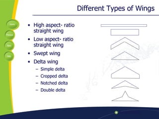
![Aspect Ratio Three dimensional effects Tells how skinny wing is AR= b 2 /S b= wingspan [m] S= planform area of wing [m 2 ]](https://image.slidesharecdn.com/subsonic-airplane-design-1226872017992421-8/85/Subsonic-Airplane-Design-22-320.jpg)
![Coefficient of Lift C L = L/( ½ ρ V 2 S) C L =coefficient of lift [dimensionless] L= lift; newton [kgm/s 2 ] ρ = air density [kg/m 3 ] V= velocity; [m/s] S= planform wing area [m 2 ]](https://image.slidesharecdn.com/subsonic-airplane-design-1226872017992421-8/85/Subsonic-Airplane-Design-23-320.jpg)
![Coefficient of Drag C D = D/( ½ ρ V 2 S) C D =coefficient of drag [dimensionless] D= drag; newton [kgm/s 2 ] ρ = air density [kg/m 3 ] V= velocity [m/s] S= planform wing area [m 2 ]](https://image.slidesharecdn.com/subsonic-airplane-design-1226872017992421-8/85/Subsonic-Airplane-Design-24-320.jpg)
![Stalling Velocity V stall = √(2/ ρ ∞ )(W/S)(1/C L max ) V stall = stalling velocity [m/s] ρ ∞ = free stream air density [ kg/m 3 ] W= weight; newtons [ kgm/s 2 ] S= planform surface area of wing [m 2 ] C L max = maximum lift coefficient [dimensionless]](https://image.slidesharecdn.com/subsonic-airplane-design-1226872017992421-8/85/Subsonic-Airplane-Design-26-320.jpg)
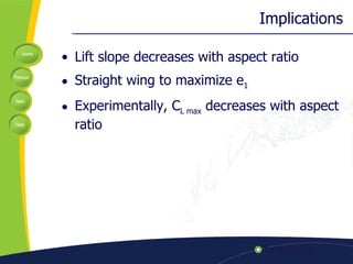
![Prandtl’s Lifting Line Theory a=a o /(1+(a o / e 1 AR) a= lift slope for finite wing [per radian] a 0 = lift slope for infinite wing [per radian] e 1 = ratio of tip chord to root chord [dimensionless] AR= b 2 /S [dimensionless]](https://image.slidesharecdn.com/subsonic-airplane-design-1226872017992421-8/85/Subsonic-Airplane-Design-29-320.jpg)
![Prandtl- Glauert Rule a o,comp = a 0 / √1 - M ∞ 2 a o = incompressible lift slope [per radian] M ∞ = free stream mach number [dimensionless]](https://image.slidesharecdn.com/subsonic-airplane-design-1226872017992421-8/85/Subsonic-Airplane-Design-31-320.jpg)
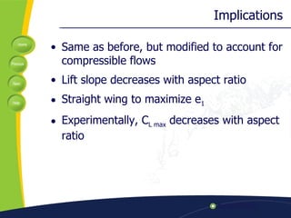
![Combined a comp = a o / √1-M ∞ +a o /( e 1 AR) a o = incompressible lift slope [per radian] a comp = compressible lift slope [per radian] M ∞ = free stream mach number [dimensionless] e 1 = ratio of tip chord to root chord [dimensionless] AR= b 2 /S [dimensionless] Works well for .3<Ma<.7](https://image.slidesharecdn.com/subsonic-airplane-design-1226872017992421-8/85/Subsonic-Airplane-Design-32-320.jpg)
![Equation for Induced Drag C Di = (C L 2 )/( (AR)e) Where: C L ; coefficient of lift [dimensionless] AR; aspect ratio [dimensionless] e; spanwise efficiency factor, how C Di for wing relates to ideal wing with the same aspect ratio [dimensionless]](https://image.slidesharecdn.com/subsonic-airplane-design-1226872017992421-8/85/Subsonic-Airplane-Design-34-320.jpg)
![Ceiling Altitude ( R/C) max = maximum rate of climb [m/sec] η pr = propeller efficiency; power available/ shaft power [dimensionless] P= power [W] W= weight newtons [ kgm/s 2 ] ρ ∞ = free stream air density [kg/m 3 ] K= Coefficient of Cl 2 in drag polar [dimensionless] C D.O= Zero lift drag coefficient [dimensionless] S= planform surface area of wing [m 2 ] L/D max = maximum lift to drag ratio [dimensionless] (R/C) max =( η pr P/W)–[(2/ ρ ∞ )√K/3C D.0 (W/S)] 1/2 *(1.55/(L/D max ))](https://image.slidesharecdn.com/subsonic-airplane-design-1226872017992421-8/85/Subsonic-Airplane-Design-37-320.jpg)
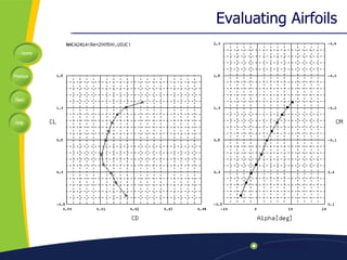
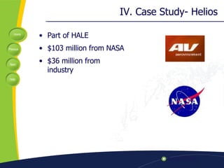
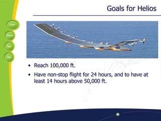


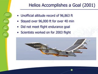
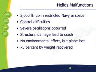


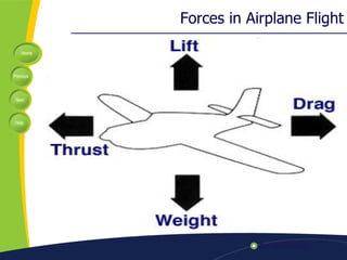
The document discusses key factors in subsonic airplane design, including lift, weight, thrust, drag, center of mass, and center of pressure. It examines ratios like the Mach number and Reynolds number that are important for interpretation. Design considerations like wing design, induced drag, and stalling velocity are covered. A case study of the Helios aircraft is presented, which set an unofficial altitude record of 96,863 feet in 2001 but later crashed during a test flight.