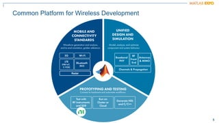
The document discusses how MATLAB and NI tools can be used together to optimize wireless system design processes. It describes how they allow designing, analyzing, and testing of wireless standards, applying AI techniques to wireless applications, jointly optimizing digital, RF, and antenna components, implementing designs on hardware, simulating radar applications, and providing hands-on learning resources. Specific examples discussed include 5G design at Qualcomm, linearization algorithm development at NanoSemi, and teaching wireless communications with USRPs.


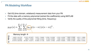
![10
10
PA
DPD
Pin [dBm]
Pout
[dBm]
PA characteristic
(actual)
Compression
Memory
RF
Baseband
Up-conversion
Down-conversion
Adaptive coefficients
Timing
Antenna loading
DPD characteristic
PA Linearization: Digital Predistortion (DPD) in Practice](https://image.slidesharecdn.com/ww-2023-expo-transforming-wireless-system-design-with-matlab-and-ni-231218164039-85878406/85/transforming-wireless-system-design-with-matlab-and-ni-pdf-11-320.jpg)