Downloaded 142 times
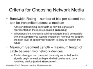
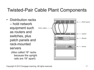
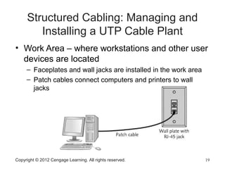
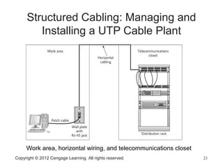
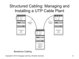

This document discusses network media for wired and wireless networking. It describes the primary types of wired network media, including copper-based twisted-pair cable and fiber-optic cables. Characteristics like bandwidth, maximum segment length, interference susceptibility, cable grade, and cost are important criteria for choosing network media. The document focuses on unshielded twisted-pair cable, describing cable categories and components of a structured UTP cable plant.