Unit-1: Physical Layer
 Types of connections
 Network Topology design
 Transmission media
 Network performance and impairments
 Switching techniques
Physical Structures
Physical Topology
Physical Topology refers to the way in which a network is laid out physically:
 Two or more devices connect to a link;
 two or more links form a topology.
The topology of a network is the geometric representation of the relationship of all the links and
linking devices (usually called nodes) to one another.
There are four basic topologies possible:
1. Mesh
2. Star
3. Bus,
4. Ring
Mesh topology
 In a mesh topology, every device has a dedicated
point-to-point link to every other device.
 number of physical links in a fully connected mesh
network with n nodes, is n(n - 1).
 if each physical link allows communication in both
directions (duplex mode), we need n(n -1) /2
duplex-mode links.
 In this topology, every device on the network must
have n - 1 input/output (IO) ports to be connected
to the other n - 1 stations.
One practical example:- the connection of telephone regional offices in which
each regional office needs to be connected to every other regional office.
advantages
 use of dedicated links guarantees that each
connection can carry its own data load, thus
eliminating the traffic problems.
 It is robust. If one link becomes unusable, it
does not incapacitate the entire system.
 there is the advantage of privacy or security.
When every message travels along a
dedicated line, only the intended recipient
sees it.
 point-to-point links make fault identification
and fault isolation easy. Traffic can be re-
routed to avoid links with suspected problems.
disadvantages
 Huge amount of cabling and the number of
I/O ports required
 every device must be connected to every
other device, installation and reconnection
are difficult.
 the sheer bulk of the wiring can be greater
than the available space can
accommodate.
 Finally, the hardware required to connect
each link (I/O ports and cable) can be
prohibitively expensive.
Star Topology
 each device has a dedicated point-to-point
link only to a central controller, usually called a
hub.
 The devices are not directly linked to one
another.
 Unlike a mesh topology, a star topology does
not allow direct traffic between devices.
 The controller acts as an exchange: If one
device wants to send data to another, it sends
the data to the controller, which then relays the
data to the other connected device
The star topology is used in local-area networks (LANs)
advantages
 less expensive than a mesh topology, as each
device needs only one link and one I/O port to
connect it to any number of others.
 easy to install and reconfigure as additions,
moves, and deletions involve only one
connection: between that device and the
hub.
 This is robust topology, If one link fails, only that
link is affected. All other links remain active.
 This factor also lends itself to easy fault
identification and fault isolation. As long as the
hub is working, it can be used to monitor link
problems and bypass defective link
disadvantages
 One big disadvantage of a star topology
is the dependency of the whole topology
on one single point, the hub. If the hub
goes down, the whole system is dead
 more cabling is required in a star than in
some other topologies (such as ring or
bus)as each node must be linked to a central
hub.
Bus Topology
 Bus topology is multipoint unlike Mesh and Star topology. One long cable acts as a backbone to
link all the devices in a network.
 Nodes are connected to the bus cable by drop lines and taps.
 A drop line is a connection running between the device and the main cable.
 A tap is a connector that either splices into the main cable or punctures the sheathing of a
cable to create a contact with the metallic core.
 As a signal travels along the backbone, some of its energy is transformed into heat. Therefore, it
becomes weaker and weaker as it travels farther and farther. For this reason, there is a limit on the
number of taps a bus can support and on the distance between those taps.
advantages
 ease of installation
 Backbone cable can be laid along the most
efficient path, then connected to the nodes
by drop lines of various lengths.
 uses less cabling than mesh or star topologies.
 In a star, for example, four network devices in
the same room require four lengths of cable
reaching all the way to the hub.
 In a bus, this redundancy is eliminated. Only the
backbone cable stretches through the entire
facility. Each drop line has to reach only as far
as the nearest point on the backbone.
disadvantages
 difficult to add new devices. As adding
new devices may require modification or
replacement of the backbone
 difficult reconnection and fault isolation
 Signal reflection at the taps can cause
degradation in quality.
 No robustness: fault or break in the bus
cable stops all transmission, even
between devices on the same side of the
problem.
advantages
 easy to install and reconfigure. Each
device is linked to only its immediate
neighbors (either physically or logically).
To add or delete a device requires
changing only two connections.
 as a signal is circulating in a ring at all
times, fault isolation is easy
disadvantages
 only constraints are media and traffic
considerations (maximum ring length and
number of devices).
 unidirectional traffic can be a
disadvantage.
 In a simple ring, a break in the ring (such
as a disabled station) can disable the
entire network.
This weakness can be solved by using a dual
ring or a switch capable of closing off the
break
Ring Topology
 Here, each device has a dedicated
point-to-point connection with only
the two devices on either side of it.
 A signal is passed along the ring in
one direction, from device to device,
until it reaches its destination.
 Each device in the ring incorporates a
repeater. When a device receives a
signal intended for another device, its
repeater regenerates the bits and
passes them along.
Hybrid Topology
Transmission Media
• Transmission media is a communication channel that carries the information from the
sender to the receiver.
• The information is usually a electromagnetic signal that is the result of a conversion of
data(to be transmitted) from another form(in bits format).
• It provides a physical path between transmitter and receiver in data communication.
• The transmission media is available in the lowest layer of the OSI reference model,
i.e., Physical layer.
• The characteristics and quality of data transmission are determined by the
characteristics of medium and signal.
Transmission media can be divided into two broad categories: guided and unguided.
• Guided − In guided media, transmitted data travels through cabling system that has a fixed
path. A signal traveling along any of these media is directed and contained by the physical
limits of the medium.
For example: copper wires, fibre optic wires, etc.
• Unguided − In unguided media, transmitted data travels through free space in form of
electromagnetic signal.
For example: radio waves, lasers, etc.
Each transmission media has its own advantages and disadvantages in terms of bandwidth,
speed, delay, cost per bit, ease of installation and maintenance, etc.
Twisted-Pair Cable
 Copper wires are the most common wires used for transmitting signals
because of good performance at low costs.
 They are most commonly used in telephone lines.
 However, if two or more wires are lying together, they can interfere with
each other’s signals. To reduce this electromagnetic interference, pair of
copper wires are twisted together in helical shape like a DNA molecule. Such
twisted copper wires are called twisted pair.
 To reduce interference between nearby twisted pairs, the twist rates are
different for each pair.
 Up to 25 twisted pair are put together in a protective covering to form
twisted pair cables that are the backbone of telephone systems and Ethernet
networks.
Advantages of twisted pair cable
Twisted pair cable are the oldest and most popular cables
all over the world. This is due to the many advantages that
they offer −
• Trained personnel easily available due to shallow
learning curve
• Can be used for both analog and digital transmissions
• Least expensive for short distances
• Entire network does not go down if a part of network is
damaged
Disadvantages of twisted pair cable
• Signal cannot travel long distances
without repeaters
• High error rate for distances greater than
100m
• Very thin and hence breaks easily
• Not suitable for broadband connections
To counter the tendency of twisted pair cables to pick up noise signals, wires are shielded in the following
three ways −
 Each twisted pair is shielded.
 Set of multiple twisted pairs in the cable is shielded.
 Each twisted pair and then all the pairs are shielded.
Such twisted pairs are called shielded twisted pair (STP) cables.
The wires that are not shielded but simply bundled together in a protective sheath are called unshielded
twisted pair (UTP) cables. These cables can have maximum length of 100 metres.
Shielding makes the cable bulky, so UTP are more popular than STP. UTP cables are used as the last mile
network connection in homes and offices.
Coaxial Cables
Coaxial cables are copper cables with
better shielding than twisted pair cables, so
that transmitted signals may travel longer
distances at higher speeds with minimum
noise.
Coaxial cables are widely used for cable
TV connections and LANs.
A coaxial cable consists of following layers,
starting from the innermost−
 Stiff copper wire as core (center conductor)
 Insulating material surrounding the core
(Dielectric)
 Closely woven braided mesh or metal foil or
a combination of the two woven
of conducting material surrounding
the insulator (second conductor)
 Protective plastic sheath encasing the wire
(outer Jacket)
Advantages of Coaxial Cables
 Excellent noise immunity
 Signals can travel longer distances at higher
speeds, e.g. 1 to 2 Gbps for 1 Km cable
 Can be used for both analog and digital signals
 Inexpensive as compared to fibre optic cables
 Easy to install and maintain
Disadvantages of Coaxial Cables
 Expensive as compared to twisted
pair cables
 Not compatible with twisted pair
cables
Optical Fiber
• Thin glass or plastic threads used to transmit data using light waves are
called optical fibre.
• Light Emitting Diodes (LEDs) or Laser Diodes (LDs) emit light waves at the source,
which is read by a detector at the other end.
• Optical fibre cable has a bundle of such threads or fibres bundled together in a
protective covering.
 if the angle of incidence I (the angle the ray makes with the line perpendicular to the
interface between the two substances) is less than the critical angle, the ray refracts
and moves closer to the surface.
 If the angle of incidence is equal to the critical angle, the light bends along the
interface.
 If the angle is greater than the critical angle, the ray reflects (makes a turn) and travels
again in the denser substance.
Each fibre is made up of these three layers,
starting with the innermost layer −
• Core made of high quality silica glass or plastic
• Cladding made of high quality silica
glass or plastic, with a lower refractive index
than the core
• Protective outer covering called buffer
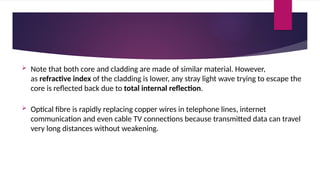
 Note that both core and cladding are made of similar material. However,
as refractive index of the cladding is lower, any stray light wave trying to escape the
core is reflected back due to total internal reflection.
 Optical fibre is rapidly replacing copper wires in telephone lines, internet
communication and even cable TV connections because transmitted data can travel
very long distances without weakening.
Advantages of Optical Fibre
Optical fibre is fast replacing copper wires because of these advantages that it
offers −
• High bandwidth
• Immune to electromagnetic interference
• Suitable for industrial and noisy areas
• Signals carrying data can travel long distances without weakening
Disadvantages of Optical Fibre
Despite long segment lengths and high bandwidth, using optical fibre may not be a
viable option for every one due to these disadvantages −
• Optical fibre cables are expensive
• Sophisticated technology required for manufacturing, installing and maintaining
optical fibre cables
• Light waves are unidirectional, so two frequencies are required for full duplex
transmission
Omni directional Antenna
 Omni directional antennas that
send out signals in all
directions.
 Based on the wavelength,
strength, and the purpose of
transmission.
 we can have several types of
antennas.
Types of radio waves
1) Short waves : AM radio
2) Very high frequency (VHF) : FM radio/ TV
3) Ultra high frequency (UHF) : TV
2) Microwaves
 These are the communication channel in which data is transmitted through air instead of
cables.
 Microwave is high frequency waves that can traveled in straight lines.
 These cannot bend or pass through obstacles.
 It is limited to particular city or community.
 The transmitter or receiver are mounted on very high tower should be in line of sight.
 Electromagnetic waves having frequencies between I and 300 GHz are called
microwaves.
 Microwaves are unidirectional
 May not be possible for long distance transmission because signals becomes weaker &
require power amplification.
 Repeaters on antennas are mounted at very high towers usually 20 to 30 miles apart to
overcomes the problem of weakening signals & line of sight.
 Microwave propagation is line-of-sight.
 Very high-frequency microwaves cannot penetrate walls. This characteristic can be a
disadvantage.
 The microwave band is relatively wide, almost 299 GHz. wider sub bands can be
assigned, and a high data rate is possible.
 Use of certain portions of the band requires permission from authorities.
NETWORK PERFORMANCE
Some important metrics used to measure Network Performance are:-
1. Bandwidth
 One characteristic that measures network performance is bandwidth.
 In networking, the term bandwidth is used in two contexts.
 The first, bandwidth in hertz, refers to the range of frequencies in a composite signal or the
range of frequencies that a channel can pass.
 The second, bandwidth in bits per second, refers to the speed of bit transmission in a
channel or link.
2. Throughput
The throughput is a measure of how much amount of data we can actually send through a
network successfully.
 bandwidth in bits per second and throughput seem the same, but they are different.
 A link may have a bandwidth of B bps, but we can only send T bps through this link with
T always less than B i.e. (T<B).
For example, we may have a link with a bandwidth of 1 Mbps, but the devices connected
to the end of the link may handle only 200 kbps. This means that we cannot send more
than 200 kbps through this link
Example A network with bandwidth of 10 Mbps can pass only an average of 12,000 frames
per minute with each frame carrying an average of 10,000 bits. What is the throughput of
this network?
Solution We can calculate the throughput as
Throughput= (12,000 x 10,000)/60=2 Mbps
The throughput is almost one-fifth of the bandwidth in this case.
3. Latency (Delay)
 The latency or delay defines how long it takes for an entire message to completely arrive
at the destination from the time the first bit is sent out from the source.
 We can say that latency is made of four components: propagation time, transmission time,
queuing time and processing delay.
Latency = propagation time + transmission time + queuing time + processing delay
a) Propagation Time
 Propagation time measures the time required for a bit to travel from the source to
the destination.
 The propagation time is calculated by dividing the distance by the propagation
speed.
Propagation time = Distance/Propagation speed
 The propagation speed of electromagnetic signals depends on the medium and on
the frequency of the signal.
For example, in a vacuum, light is propagated with a speed of 3 x 10⁸
m/s. It is
lower in air; it is much lower in cable.
Example What is the propagation time if the distance between the two points is
12,000 km? Assume the propagation speed to be 2.4 x 10⁸
m/s in cable.
Solution We can calculate the propagation time as ..
Propagation time = (12000 x 1000)/(2.4 x 108
) = 50 ms
b) Transmission Time
 In data communications we don't send just 1 bit, we send a message. The first bit may
take a time equal to the propagation time to reach its destination; the last bit also may
take the same amount of time.
 However, there is a time between the first bit leaving the sender and the last bit arriving
at the receiver. The first bit leaves earlier and arrives earlier; the last bit leaves later and
arrives later.
 The time required for transmission of a message depends on the size of the message
and the bandwidth of the channel.
Transmission time =Message size/ Bandwidth
Example What are the propagation time and the transmission time for a 2.5-kbyte message
(an e-mail) if the bandwidth of the network is 1 Gbps? Assume that the distance between
the sender and the receiver is 12,000 km and that light travels at 2.4 x 10⁸
m/s.
Solution
We can calculate the propagation and transmission time as ..
PropagatIon time = (12000 x 1000) /2.4 x 108
=50 ms
Transmission tIme = (2500 x 8)/ 109
= 0.020 ms
Note that in this case, because the message is short and the bandwidth is high, the
dominant factor is the propagation time, not the transmission time. The transmission time
can be ignored.
Example: What are the propagation time and the transmission time for a 5-Mbyte
message (an image) if the bandwidth of the network is 1 Mbps? Assume that the distance
between the sender and the receiver is 12,000 km and that light travels at 2.4 x 10⁸
m/s.
Solution: We can calculate the propagation and transmission times as
Propagation time = (12 000 X 1000)/ 2.4x 108
= 50 ms
Transmission time = (5,000,000 x 8)/ 106
=40 s
Note that in this case, because the message is very long and the bandwidth is not very
high, the dominant factor is the transmission time, not the propagation time. The
propagation time can be ignored.
c) Queuing Time
The third component in latency is the queuing time, the time needed for each intermediate
or end device to hold the message before it can be processed.
The queuing time is not a fixed factor; it changes with the load imposed on the network.
When there is heavy traffic on the network, the queuing time increases.
An intermediate device, such as a router, queues the arrived messages and processes them
one by one. If there are many messages, each message will have to wait.
Numerical
1. What is the total delay (latency) for a frame of size 5 million bits that is being sent on a link with
10 routers each having a queuing time of 2 μs and a processing time of 1 μs. The length of the link is
2000 Km. The speed of light inside the link is 2 × 10⁸ m/s. The link has a bandwidth of 5 Mbps.
Which component of the total delay is dominant? Which one is negligible?
2. sender wants to send packet of size 10^4 bytes to receiver. sender and router are connected via
router. propagation time and bandwidth of each link is 1 millisecond and 10^6 bps. find total delay.
assume queuing time and processing time at router is 5 and 10 millisecond.
4. Jitter
Another performance issue that is related to delay is jitter.
Jitter is a problem if different packets of data encounter different delays and the
application using the data at the receiver site is time-sensitive (audio and video data, for
example).
If the delay for the first packet is 20 ms, for the second is 45 ms, and for the third is 40 ms,
then the real-time application that uses the packets endures jitter.
TRANSMISSION IMPAIRMENT
 Signals travel through transmission media, which are not perfect.
 The imperfection causes signal impairment.
 This means that the signal at the beginning of the medium is not the same as
the signal at the end of the medium. What is sent is not what is received.
 Three causes of impairment are: attenuation, distortion, and noise
1. Attenuation
 Attenuation means a loss of energy.
 When a signal, simple or composite, travels through a medium, it loses some of its energy in
overcoming the resistance of the medium. That is why a wire carrying electric signals gets
warm, if not hot, after a while.
 Some of the electrical energy in the signal is converted to heat.
 To compensate for this loss, amplifiers are used to amplify the signal.
 Decibel
The decibel (dB) is the unit that measures the relative strengths of two signals or
one signal at two different points.
The decibel is negative if a signal is attenuated and positive if a signal is amplified.
Variables PI and P2 are the powers of a signal at points 1 and 2, respectively
Example: Suppose a signal travels through a transmission medium and its power is reduced to
one-half. This means that P2 = ½ P1.
Solution: In this case, the attenuation (loss of power) can be calculated as:
= 10loglO P2/P1
= 10logl0 0.5PI/P1 = 10 Ioglo0.5 = 10(-0.3) = -3 dB
A loss of 3 dB (-3 dB) is equivalent to losing one-half the power.
Example: A signal travels through an amplifier, and its power is increased 10 times. This means
that P2= 10 P1 In this case, the amplification (gain of power) can be calculated as
2. Distortion
 Distortion means that the signal changes its form or shape.
 Distortion can occur in a composite signal made of different frequencies.
 Each signal component has its own propagation speed through a medium and,
therefore, its own delay in arriving at the final destination.
 Differences in delay may create a difference in phase if the delay is not exactly
the same as the period duration.
In other words, signal components at the receiver have phases different from what
they had at the sender. The shape of the composite signal is therefore not the
same.
3. Noise
 Noise is another cause of impairment.
 Several types of noise, such as thermal noise, induced noise, crosstalk, and impulse noise,
may corrupt the signal.
 Thermal noise is the random motion of electrons in a wire which creates an extra
signal not originally sent by the transmitter.
 Induced noise comes from sources such as motors and appliances. These devices act
as a sending antenna, and the transmission medium acts as the receiving antenna.
 Crosstalk is the effect of one wire on the other. One wire acts as a sending antenna
and the other as the receiving antenna.
 Impulse noise is a spike (a signal with high energy in a very short time) that comes from
power lines, lightning, and so on.
 Signal-to-Noise Ratio (SNR)
It is defined as
SNR =average signal power/average noise power
 SNR is actually the ratio of what is wanted (signal) to what is not wanted (noise).
 A high SNR means the signal is less corrupted by noise;
 a low SNR means the signal is more corrupted by noise.
 Because SNR is the ratio of two powers, it is often described in decibel units,
 SNRdB, defined as
Switching Techniques
Switching
 For very large networks, when we have to connect multiple devices, the MESH
topology or STAR topologies are impractical and wasteful to make one-to-one
communication possible.
 The number and length of the links require too much infrastructure to be cost-
efficient, and the majority of those links would be idle most of the time.
 Other topologies employing multipoint connections, such as a bus, are ruled out
because the distances between devices and the total number of devices will
increase beyond the capacities of the media and equipment.
A better solution is Switching.
Switched network
 A switched network consists of a series of interlinked nodes, called switches.
 Switches are devices capable of creating temporary connections between two or more devices
linked to the switch.
 In a switched network, some of these nodes are connected to the end systems (computers or
telephones, for example). Others are used only for routing.
Each switch is
connected to
multiple links.
Switched
Network
Types of Switching
Three broad categories of switching :
1. CIRCUIT-SWITCHING
 Circuit switching takes place at the physical
layer.
 A circuit-switched network is made of a set of
switches connected by physical links in which
each link is divided into n channels by using
FDM or TDM.
 A connection between two stations is a
dedicated path made of one or more links.
 However, each connection uses only one
dedicated channel on each link. Circuit-switched networks
Three Phases
The actual communication in a circuit-switched network requires three
phases:
1. connection setup : When end system A needs to communicate with
end system M, system A needs to request a connection to M that must
be accepted by all switches as well as by M itself. This is called the
setup phase;
2. data transfer: a circuit (channel) is reserved on each link, and the
combination of circuits or channels defines the dedicated path. After
the dedicated path made of connected circuits (channels) is
established, data transfer can take place.
3. connection teardown: After all data have been transferred, the circuits
are tear down.
Key points of Circuit Switching
 Before starting communication, the stations must make a reservation for the resources to be
used during the communication.
 These resources, such as channels (bandwidth in FDM and time slots in TDM), switch buffers,
switch processing time, and switch input/output ports, must remain dedicated during the entire
duration of data transfer until the teardown phase.
 Data transferred between the two stations are not packetized. The data are a continuous flow
sent by the source station and received by the destination station, although there may be periods
of silence.
 There is no addressing involved during data transfer. The switches route the data based on their
occupied band (FDM) or time slot (TDM).
• More expensive than any other switching techniques,
2. Packet-switched network
 In packet-switched network, the message needs to be divided into packets of fixed/variable
size. The size of the packet is determined by the network and the governing protocol.
 In this switching, there is no resource allocation for a packet i.e no reserved bandwidth on
the links, and there is no scheduled processing time for each packet.
 Resources are allocated on demand. The allocation is done on a first- come, first-served basis.
 When a switch receives a packet, no matter what is the source or destination, the packet must
wait if there are other packets being processed.
 As with other systems in our daily life, this lack of reservation may create delay.
a) Datagram Switching
 Datagram switching is normally done at the network layer.
 In a datagram network, each packet is treated independently of all others. Even
if a packet is part of a multipacket transmission, the network treats it as though it
existed alone.
 Packets in this approach are referred to as datagrams.
 The datagram networks are sometimes referred to as connectionless networks.
 The switches in a datagram network are traditionally referred to as routers.
Example: Sending message from station A to
station X.
 The message is first divided into four packets (or
datagrams).
 There are no setup or teardown phases.
 the packets, each with the same destination
address, do not follow the same route, and they
may arrive out of sequence at the exit point node
(or the destination).
 Reordering is done at the destination point based
on the sequence number of the packets.
 It is possible for a packet to be destroyed if one of
the nodes on its way is crashed momentarily. Thus,
all its queued packets may be lost.
Routing Table
As there are no setup or teardown phases, how are the
packets routed to their destinations in a datagram network?
 In this type of network, each switch (or packet switch) has a
routing table which is based on the destination address.
 The routing tables are dynamic and are updated periodically.
 The destination addresses and the corresponding forwarding
output ports are recorded in the tables
b) VIRTUAL-CIRCUIT Switching
A virtual-circuit network is a cross between a circuit-switched
network and a datagram network. It has some characteristics of both.
1. As in a circuit-switched network, there are setup and teardown phases
in addition to the data transfer phase.
2. Resources can be allocated during the setup phase, as in a circuit-
switched network, or on demand, as in a datagram network.
3. As in a datagram network, data are packetized and each packet carries
an address of the next immediate connected switch, not end-to-end
(destination) address.
4. As in a circuit-switched network, all packets follow the same path
established during the connection.
5. A virtual-circuit network is normally implemented in the data link
layer,.
Addressing In a virtual-circuit network,
Two types of addressing are involved:
1. Global Addressing: A source or a destination needs to have a (global address)-an address that can
be unique in the scope of the network or internationally if the network is part of an international
network.
2. Local Addressing (Virtual-Circuit Identifier): The identifier that is actually used for data transfer
is called the virtual-circuit identifier (Vel).
A vel, unlike a global address, is a small number that has only switch scope; it is used by a frame
between two switches. When a frame arrives at a switch, it has a VCI; when it leaves, it has a different
VCl.
Switch and tables in a virtual-circuit network
Three Phases
As in a circuit-switched network, a source and destination need to go through three
phases in a virtual-circuit network: setup, data transfer, and teardown.
1. In the setup phase, the source and destination use their global addresses to help
switches make table entries for the connection.
2. In the teardown phase, the source and destination inform the switches to delete
the corresponding entry.
3. Data transfer occurs between these two phases.
1. Setup phase:
In the setup phase, a switch creates an entry for a virtual circuit. For example, suppose
source A needs to create a virtual circuit to B.
Two steps are required:
a) the setup request
b) the acknowledgment
a) Setup Request
Setup Request
A setup request frame is sent from the source to the destination.
a. Source A sends a setup frame to switch 1.
b. Switch 1 receives the setup request frame. The switch, has a routing table and knows that a frame going
from A to B goes out through port 3. The switch creates an entry in its table for this virtual circuit, but it is only
able to fill three of the four columns i.e. (the incoming port (1) and chooses an available incoming VCI (14)
and the outgoing port (3)). It does not yet know the outgoing VCI, which will be found during the
acknowledgment step. The switch then forwards the frame through port 3 to switch 2.
c. Switch 2 receives the setup request frame. The same events happen here as at switch 1; three columns of
the table are completed: in this case, incoming port (l), incoming VCI (66), and outgoing port (2).
d. Switch 3 receives the setup request frame. Again, three columns are completed: incoming port (2),
incoming VCI (22), and outgoing port (3).
e. Destination B receives the setup frame, and if it is ready to receive frames from A, it assigns a VCI to the
incoming frames that come from A, in this case 77. This VCI lets the destination know that the frames come
from A, and not other sources.
b) the acknowledgment
Acknowledgment
A special frame, called the acknowledgment frame, completes the entries in the switching tables.
a. The destination sends an acknowledgment to switch 3. The acknowledgment carries the global
source and destination addresses so the switch knows which entry in the table is to be completed.
The frame also carries VCI 77, chosen by the destination as the incoming VCI for frames from A.
Switch 3 uses this VCI to complete the outgoing VCI column for this entry. Note that 77 is the
incoming VCI for destination B, but the outgoing VCI for switch 3.
b. Switch 3 sends an acknowledgment to switch 2 that contains its incoming VCI in the table, chosen
in the previous step. Switch 2 uses this as the outgoing VCI in the table.
c. Switch 2 sends an acknowledgment to switch 1 that contains its incoming VCI in the table, chosen
in the previous step. Switch 1 uses this as the outgoing VCI in the table.
d. Finally switch 1 sends an acknowledgment to source A that contains its incoming VCI in the table,
chosen in the previous step.
Data Transfer Phase
To transfer a frame from a source to its
destination, all switches need to have a
table entry for this virtual circuit.
For eg. a frame arriving at
port 1 with a VCI of 14. When the frame
arrives, the switch looks in its table to find
port 1 and a VCI of 14. When it is found,
the switch knows to change the VCI to 22
and send out the frame from port 3.
Given fig. shows how a frame from source
A reaches destination B and how its VCI
changes during the trip. Each switch
changes the VCI and routes the frame.
 Teardown Phase:
In this phase, source A, after sending all frames to B, sends a special frame called a teardown
request.
Destination B responds with a teardown confirmation frame. All switches delete the
corresponding entry from their tables.
 Efficiency
The efficiency of a datagram network is better than that of a circuit-switched network; resources
are allocated only when there are packets to be transferred.
If a source sends a packet and there is a delay of a few minutes before another packet can be
sent, the resources can be reallocated during these minutes for other packets from other sources.
 Delay
There may be greater delay in a datagram network than in a virtual-circuit network. Although
there are no setup and teardown phases, each packet may experience a wait at a switch before it
is forwarded. the delay is not uniform for the packets of a message.
Disadvantages
• They are unsuitable for applications that cannot afford delays in
communication like high quality voice calls.
• Packet switching high installation costs.
• They require complex protocols for delivery.
• Network problems may introduce errors in packets, delay in delivery of
packets or loss of packets. ...
Message Switching
 With message switching there is no need to establish a dedicated path between two stations.
 When a station sends a message, the destination address is appended to the message.
 The message is then transmitted through the network, in its entirety, from node to node.
 Each node receives the entire message, stores it in its entirety on disk, and then transmits the
message to the next node.
 This type of network is called a store-and-forward network.
 A message-switching node is typically
a general-purpose computer.
 The device needs sufficient secondary-
storage capacity to store the incoming
messages, which could be long.
 A time delay is introduced using this
type of scheme due to store- and-
forward time, plus the time required to
find the next node in the transmission
path.
 Advantages:
 Channel efficiency can be greater compared to circuit-switched systems, because more
devices are sharing the channel.
 Traffic congestion can be reduced, because messages may be temporarily stored in
route.
 Message priorities can be established due to store-and-forward technique.
 Message broadcasting can be achieved with the use of broadcast address appended in
the message.
 Disadvantages:
 Message switching is not compatible with interactive
applications.
 Store-and-forward devices are expensive, because they must have
large disks to hold potentially long messages.

Unit-1 (Part-b).pptxxxxxxxxxxxxxxxxxxxxx

  • 1.
    Unit-1: Physical Layer Types of connections  Network Topology design  Transmission media  Network performance and impairments  Switching techniques
  • 2.
  • 3.
    Physical Topology Physical Topologyrefers to the way in which a network is laid out physically:  Two or more devices connect to a link;  two or more links form a topology. The topology of a network is the geometric representation of the relationship of all the links and linking devices (usually called nodes) to one another. There are four basic topologies possible: 1. Mesh 2. Star 3. Bus, 4. Ring
  • 4.
    Mesh topology  Ina mesh topology, every device has a dedicated point-to-point link to every other device.  number of physical links in a fully connected mesh network with n nodes, is n(n - 1).  if each physical link allows communication in both directions (duplex mode), we need n(n -1) /2 duplex-mode links.  In this topology, every device on the network must have n - 1 input/output (IO) ports to be connected to the other n - 1 stations. One practical example:- the connection of telephone regional offices in which each regional office needs to be connected to every other regional office.
  • 5.
    advantages  use ofdedicated links guarantees that each connection can carry its own data load, thus eliminating the traffic problems.  It is robust. If one link becomes unusable, it does not incapacitate the entire system.  there is the advantage of privacy or security. When every message travels along a dedicated line, only the intended recipient sees it.  point-to-point links make fault identification and fault isolation easy. Traffic can be re- routed to avoid links with suspected problems. disadvantages  Huge amount of cabling and the number of I/O ports required  every device must be connected to every other device, installation and reconnection are difficult.  the sheer bulk of the wiring can be greater than the available space can accommodate.  Finally, the hardware required to connect each link (I/O ports and cable) can be prohibitively expensive.
  • 6.
    Star Topology  eachdevice has a dedicated point-to-point link only to a central controller, usually called a hub.  The devices are not directly linked to one another.  Unlike a mesh topology, a star topology does not allow direct traffic between devices.  The controller acts as an exchange: If one device wants to send data to another, it sends the data to the controller, which then relays the data to the other connected device The star topology is used in local-area networks (LANs)
  • 7.
    advantages  less expensivethan a mesh topology, as each device needs only one link and one I/O port to connect it to any number of others.  easy to install and reconfigure as additions, moves, and deletions involve only one connection: between that device and the hub.  This is robust topology, If one link fails, only that link is affected. All other links remain active.  This factor also lends itself to easy fault identification and fault isolation. As long as the hub is working, it can be used to monitor link problems and bypass defective link disadvantages  One big disadvantage of a star topology is the dependency of the whole topology on one single point, the hub. If the hub goes down, the whole system is dead  more cabling is required in a star than in some other topologies (such as ring or bus)as each node must be linked to a central hub.
  • 8.
    Bus Topology  Bustopology is multipoint unlike Mesh and Star topology. One long cable acts as a backbone to link all the devices in a network.  Nodes are connected to the bus cable by drop lines and taps.  A drop line is a connection running between the device and the main cable.  A tap is a connector that either splices into the main cable or punctures the sheathing of a cable to create a contact with the metallic core.  As a signal travels along the backbone, some of its energy is transformed into heat. Therefore, it becomes weaker and weaker as it travels farther and farther. For this reason, there is a limit on the number of taps a bus can support and on the distance between those taps.
  • 9.
    advantages  ease ofinstallation  Backbone cable can be laid along the most efficient path, then connected to the nodes by drop lines of various lengths.  uses less cabling than mesh or star topologies.  In a star, for example, four network devices in the same room require four lengths of cable reaching all the way to the hub.  In a bus, this redundancy is eliminated. Only the backbone cable stretches through the entire facility. Each drop line has to reach only as far as the nearest point on the backbone. disadvantages  difficult to add new devices. As adding new devices may require modification or replacement of the backbone  difficult reconnection and fault isolation  Signal reflection at the taps can cause degradation in quality.  No robustness: fault or break in the bus cable stops all transmission, even between devices on the same side of the problem.
  • 10.
    advantages  easy toinstall and reconfigure. Each device is linked to only its immediate neighbors (either physically or logically). To add or delete a device requires changing only two connections.  as a signal is circulating in a ring at all times, fault isolation is easy disadvantages  only constraints are media and traffic considerations (maximum ring length and number of devices).  unidirectional traffic can be a disadvantage.  In a simple ring, a break in the ring (such as a disabled station) can disable the entire network. This weakness can be solved by using a dual ring or a switch capable of closing off the break
  • 11.
    Ring Topology  Here,each device has a dedicated point-to-point connection with only the two devices on either side of it.  A signal is passed along the ring in one direction, from device to device, until it reaches its destination.  Each device in the ring incorporates a repeater. When a device receives a signal intended for another device, its repeater regenerates the bits and passes them along.
  • 12.
  • 13.
    Transmission Media • Transmissionmedia is a communication channel that carries the information from the sender to the receiver. • The information is usually a electromagnetic signal that is the result of a conversion of data(to be transmitted) from another form(in bits format). • It provides a physical path between transmitter and receiver in data communication. • The transmission media is available in the lowest layer of the OSI reference model, i.e., Physical layer. • The characteristics and quality of data transmission are determined by the characteristics of medium and signal.
  • 14.
    Transmission media canbe divided into two broad categories: guided and unguided.
  • 15.
    • Guided −In guided media, transmitted data travels through cabling system that has a fixed path. A signal traveling along any of these media is directed and contained by the physical limits of the medium. For example: copper wires, fibre optic wires, etc. • Unguided − In unguided media, transmitted data travels through free space in form of electromagnetic signal. For example: radio waves, lasers, etc. Each transmission media has its own advantages and disadvantages in terms of bandwidth, speed, delay, cost per bit, ease of installation and maintenance, etc.
  • 16.
    Twisted-Pair Cable  Copperwires are the most common wires used for transmitting signals because of good performance at low costs.  They are most commonly used in telephone lines.  However, if two or more wires are lying together, they can interfere with each other’s signals. To reduce this electromagnetic interference, pair of copper wires are twisted together in helical shape like a DNA molecule. Such twisted copper wires are called twisted pair.  To reduce interference between nearby twisted pairs, the twist rates are different for each pair.  Up to 25 twisted pair are put together in a protective covering to form twisted pair cables that are the backbone of telephone systems and Ethernet networks.
  • 17.
    Advantages of twistedpair cable Twisted pair cable are the oldest and most popular cables all over the world. This is due to the many advantages that they offer − • Trained personnel easily available due to shallow learning curve • Can be used for both analog and digital transmissions • Least expensive for short distances • Entire network does not go down if a part of network is damaged Disadvantages of twisted pair cable • Signal cannot travel long distances without repeaters • High error rate for distances greater than 100m • Very thin and hence breaks easily • Not suitable for broadband connections
  • 19.
    To counter thetendency of twisted pair cables to pick up noise signals, wires are shielded in the following three ways −  Each twisted pair is shielded.  Set of multiple twisted pairs in the cable is shielded.  Each twisted pair and then all the pairs are shielded. Such twisted pairs are called shielded twisted pair (STP) cables. The wires that are not shielded but simply bundled together in a protective sheath are called unshielded twisted pair (UTP) cables. These cables can have maximum length of 100 metres. Shielding makes the cable bulky, so UTP are more popular than STP. UTP cables are used as the last mile network connection in homes and offices.
  • 22.
    Coaxial Cables Coaxial cablesare copper cables with better shielding than twisted pair cables, so that transmitted signals may travel longer distances at higher speeds with minimum noise. Coaxial cables are widely used for cable TV connections and LANs.
  • 23.
    A coaxial cableconsists of following layers, starting from the innermost−  Stiff copper wire as core (center conductor)  Insulating material surrounding the core (Dielectric)  Closely woven braided mesh or metal foil or a combination of the two woven of conducting material surrounding the insulator (second conductor)  Protective plastic sheath encasing the wire (outer Jacket)
  • 24.
    Advantages of CoaxialCables  Excellent noise immunity  Signals can travel longer distances at higher speeds, e.g. 1 to 2 Gbps for 1 Km cable  Can be used for both analog and digital signals  Inexpensive as compared to fibre optic cables  Easy to install and maintain Disadvantages of Coaxial Cables  Expensive as compared to twisted pair cables  Not compatible with twisted pair cables
  • 26.
    Optical Fiber • Thinglass or plastic threads used to transmit data using light waves are called optical fibre. • Light Emitting Diodes (LEDs) or Laser Diodes (LDs) emit light waves at the source, which is read by a detector at the other end. • Optical fibre cable has a bundle of such threads or fibres bundled together in a protective covering.
  • 27.
     if theangle of incidence I (the angle the ray makes with the line perpendicular to the interface between the two substances) is less than the critical angle, the ray refracts and moves closer to the surface.  If the angle of incidence is equal to the critical angle, the light bends along the interface.  If the angle is greater than the critical angle, the ray reflects (makes a turn) and travels again in the denser substance.
  • 28.
    Each fibre ismade up of these three layers, starting with the innermost layer − • Core made of high quality silica glass or plastic • Cladding made of high quality silica glass or plastic, with a lower refractive index than the core • Protective outer covering called buffer
  • 29.
     Note thatboth core and cladding are made of similar material. However, as refractive index of the cladding is lower, any stray light wave trying to escape the core is reflected back due to total internal reflection.  Optical fibre is rapidly replacing copper wires in telephone lines, internet communication and even cable TV connections because transmitted data can travel very long distances without weakening.
  • 30.
    Advantages of OpticalFibre Optical fibre is fast replacing copper wires because of these advantages that it offers − • High bandwidth • Immune to electromagnetic interference • Suitable for industrial and noisy areas • Signals carrying data can travel long distances without weakening
  • 31.
    Disadvantages of OpticalFibre Despite long segment lengths and high bandwidth, using optical fibre may not be a viable option for every one due to these disadvantages − • Optical fibre cables are expensive • Sophisticated technology required for manufacturing, installing and maintaining optical fibre cables • Light waves are unidirectional, so two frequencies are required for full duplex transmission
  • 34.
    Omni directional Antenna Omni directional antennas that send out signals in all directions.  Based on the wavelength, strength, and the purpose of transmission.  we can have several types of antennas.
  • 35.
    Types of radiowaves 1) Short waves : AM radio 2) Very high frequency (VHF) : FM radio/ TV 3) Ultra high frequency (UHF) : TV
  • 36.
    2) Microwaves  Theseare the communication channel in which data is transmitted through air instead of cables.  Microwave is high frequency waves that can traveled in straight lines.  These cannot bend or pass through obstacles.  It is limited to particular city or community.  The transmitter or receiver are mounted on very high tower should be in line of sight.  Electromagnetic waves having frequencies between I and 300 GHz are called microwaves.  Microwaves are unidirectional
  • 37.
     May notbe possible for long distance transmission because signals becomes weaker & require power amplification.  Repeaters on antennas are mounted at very high towers usually 20 to 30 miles apart to overcomes the problem of weakening signals & line of sight.  Microwave propagation is line-of-sight.  Very high-frequency microwaves cannot penetrate walls. This characteristic can be a disadvantage.  The microwave band is relatively wide, almost 299 GHz. wider sub bands can be assigned, and a high data rate is possible.  Use of certain portions of the band requires permission from authorities.
  • 40.
    NETWORK PERFORMANCE Some importantmetrics used to measure Network Performance are:- 1. Bandwidth  One characteristic that measures network performance is bandwidth.  In networking, the term bandwidth is used in two contexts.  The first, bandwidth in hertz, refers to the range of frequencies in a composite signal or the range of frequencies that a channel can pass.  The second, bandwidth in bits per second, refers to the speed of bit transmission in a channel or link.
  • 41.
    2. Throughput The throughputis a measure of how much amount of data we can actually send through a network successfully.  bandwidth in bits per second and throughput seem the same, but they are different.  A link may have a bandwidth of B bps, but we can only send T bps through this link with T always less than B i.e. (T<B). For example, we may have a link with a bandwidth of 1 Mbps, but the devices connected to the end of the link may handle only 200 kbps. This means that we cannot send more than 200 kbps through this link
  • 42.
    Example A networkwith bandwidth of 10 Mbps can pass only an average of 12,000 frames per minute with each frame carrying an average of 10,000 bits. What is the throughput of this network? Solution We can calculate the throughput as Throughput= (12,000 x 10,000)/60=2 Mbps The throughput is almost one-fifth of the bandwidth in this case.
  • 43.
    3. Latency (Delay) The latency or delay defines how long it takes for an entire message to completely arrive at the destination from the time the first bit is sent out from the source.  We can say that latency is made of four components: propagation time, transmission time, queuing time and processing delay. Latency = propagation time + transmission time + queuing time + processing delay
  • 44.
    a) Propagation Time Propagation time measures the time required for a bit to travel from the source to the destination.  The propagation time is calculated by dividing the distance by the propagation speed. Propagation time = Distance/Propagation speed  The propagation speed of electromagnetic signals depends on the medium and on the frequency of the signal. For example, in a vacuum, light is propagated with a speed of 3 x 10⁸ m/s. It is lower in air; it is much lower in cable.
  • 45.
    Example What isthe propagation time if the distance between the two points is 12,000 km? Assume the propagation speed to be 2.4 x 10⁸ m/s in cable. Solution We can calculate the propagation time as .. Propagation time = (12000 x 1000)/(2.4 x 108 ) = 50 ms
  • 46.
    b) Transmission Time In data communications we don't send just 1 bit, we send a message. The first bit may take a time equal to the propagation time to reach its destination; the last bit also may take the same amount of time.  However, there is a time between the first bit leaving the sender and the last bit arriving at the receiver. The first bit leaves earlier and arrives earlier; the last bit leaves later and arrives later.  The time required for transmission of a message depends on the size of the message and the bandwidth of the channel. Transmission time =Message size/ Bandwidth
  • 47.
    Example What arethe propagation time and the transmission time for a 2.5-kbyte message (an e-mail) if the bandwidth of the network is 1 Gbps? Assume that the distance between the sender and the receiver is 12,000 km and that light travels at 2.4 x 10⁸ m/s. Solution We can calculate the propagation and transmission time as .. PropagatIon time = (12000 x 1000) /2.4 x 108 =50 ms Transmission tIme = (2500 x 8)/ 109 = 0.020 ms Note that in this case, because the message is short and the bandwidth is high, the dominant factor is the propagation time, not the transmission time. The transmission time can be ignored.
  • 48.
    Example: What arethe propagation time and the transmission time for a 5-Mbyte message (an image) if the bandwidth of the network is 1 Mbps? Assume that the distance between the sender and the receiver is 12,000 km and that light travels at 2.4 x 10⁸ m/s. Solution: We can calculate the propagation and transmission times as Propagation time = (12 000 X 1000)/ 2.4x 108 = 50 ms Transmission time = (5,000,000 x 8)/ 106 =40 s Note that in this case, because the message is very long and the bandwidth is not very high, the dominant factor is the transmission time, not the propagation time. The propagation time can be ignored.
  • 49.
    c) Queuing Time Thethird component in latency is the queuing time, the time needed for each intermediate or end device to hold the message before it can be processed. The queuing time is not a fixed factor; it changes with the load imposed on the network. When there is heavy traffic on the network, the queuing time increases. An intermediate device, such as a router, queues the arrived messages and processes them one by one. If there are many messages, each message will have to wait.
  • 50.
    Numerical 1. What isthe total delay (latency) for a frame of size 5 million bits that is being sent on a link with 10 routers each having a queuing time of 2 μs and a processing time of 1 μs. The length of the link is 2000 Km. The speed of light inside the link is 2 × 10⁸ m/s. The link has a bandwidth of 5 Mbps. Which component of the total delay is dominant? Which one is negligible? 2. sender wants to send packet of size 10^4 bytes to receiver. sender and router are connected via router. propagation time and bandwidth of each link is 1 millisecond and 10^6 bps. find total delay. assume queuing time and processing time at router is 5 and 10 millisecond.
  • 51.
    4. Jitter Another performanceissue that is related to delay is jitter. Jitter is a problem if different packets of data encounter different delays and the application using the data at the receiver site is time-sensitive (audio and video data, for example). If the delay for the first packet is 20 ms, for the second is 45 ms, and for the third is 40 ms, then the real-time application that uses the packets endures jitter.
  • 52.
    TRANSMISSION IMPAIRMENT  Signalstravel through transmission media, which are not perfect.  The imperfection causes signal impairment.  This means that the signal at the beginning of the medium is not the same as the signal at the end of the medium. What is sent is not what is received.  Three causes of impairment are: attenuation, distortion, and noise
  • 53.
    1. Attenuation  Attenuationmeans a loss of energy.  When a signal, simple or composite, travels through a medium, it loses some of its energy in overcoming the resistance of the medium. That is why a wire carrying electric signals gets warm, if not hot, after a while.  Some of the electrical energy in the signal is converted to heat.  To compensate for this loss, amplifiers are used to amplify the signal.
  • 54.
     Decibel The decibel(dB) is the unit that measures the relative strengths of two signals or one signal at two different points. The decibel is negative if a signal is attenuated and positive if a signal is amplified. Variables PI and P2 are the powers of a signal at points 1 and 2, respectively
  • 55.
    Example: Suppose asignal travels through a transmission medium and its power is reduced to one-half. This means that P2 = ½ P1. Solution: In this case, the attenuation (loss of power) can be calculated as: = 10loglO P2/P1 = 10logl0 0.5PI/P1 = 10 Ioglo0.5 = 10(-0.3) = -3 dB A loss of 3 dB (-3 dB) is equivalent to losing one-half the power. Example: A signal travels through an amplifier, and its power is increased 10 times. This means that P2= 10 P1 In this case, the amplification (gain of power) can be calculated as
  • 57.
    2. Distortion  Distortionmeans that the signal changes its form or shape.  Distortion can occur in a composite signal made of different frequencies.  Each signal component has its own propagation speed through a medium and, therefore, its own delay in arriving at the final destination.  Differences in delay may create a difference in phase if the delay is not exactly the same as the period duration. In other words, signal components at the receiver have phases different from what they had at the sender. The shape of the composite signal is therefore not the same.
  • 59.
    3. Noise  Noiseis another cause of impairment.  Several types of noise, such as thermal noise, induced noise, crosstalk, and impulse noise, may corrupt the signal.  Thermal noise is the random motion of electrons in a wire which creates an extra signal not originally sent by the transmitter.  Induced noise comes from sources such as motors and appliances. These devices act as a sending antenna, and the transmission medium acts as the receiving antenna.  Crosstalk is the effect of one wire on the other. One wire acts as a sending antenna and the other as the receiving antenna.  Impulse noise is a spike (a signal with high energy in a very short time) that comes from power lines, lightning, and so on.
  • 61.
     Signal-to-Noise Ratio(SNR) It is defined as SNR =average signal power/average noise power  SNR is actually the ratio of what is wanted (signal) to what is not wanted (noise).  A high SNR means the signal is less corrupted by noise;  a low SNR means the signal is more corrupted by noise.  Because SNR is the ratio of two powers, it is often described in decibel units,  SNRdB, defined as
  • 64.
  • 65.
    Switching  For verylarge networks, when we have to connect multiple devices, the MESH topology or STAR topologies are impractical and wasteful to make one-to-one communication possible.  The number and length of the links require too much infrastructure to be cost- efficient, and the majority of those links would be idle most of the time.  Other topologies employing multipoint connections, such as a bus, are ruled out because the distances between devices and the total number of devices will increase beyond the capacities of the media and equipment. A better solution is Switching.
  • 66.
    Switched network  Aswitched network consists of a series of interlinked nodes, called switches.  Switches are devices capable of creating temporary connections between two or more devices linked to the switch.  In a switched network, some of these nodes are connected to the end systems (computers or telephones, for example). Others are used only for routing. Each switch is connected to multiple links. Switched Network
  • 67.
    Types of Switching Threebroad categories of switching :
  • 68.
    1. CIRCUIT-SWITCHING  Circuitswitching takes place at the physical layer.  A circuit-switched network is made of a set of switches connected by physical links in which each link is divided into n channels by using FDM or TDM.  A connection between two stations is a dedicated path made of one or more links.  However, each connection uses only one dedicated channel on each link. Circuit-switched networks
  • 69.
    Three Phases The actualcommunication in a circuit-switched network requires three phases: 1. connection setup : When end system A needs to communicate with end system M, system A needs to request a connection to M that must be accepted by all switches as well as by M itself. This is called the setup phase; 2. data transfer: a circuit (channel) is reserved on each link, and the combination of circuits or channels defines the dedicated path. After the dedicated path made of connected circuits (channels) is established, data transfer can take place. 3. connection teardown: After all data have been transferred, the circuits are tear down.
  • 70.
    Key points ofCircuit Switching  Before starting communication, the stations must make a reservation for the resources to be used during the communication.  These resources, such as channels (bandwidth in FDM and time slots in TDM), switch buffers, switch processing time, and switch input/output ports, must remain dedicated during the entire duration of data transfer until the teardown phase.  Data transferred between the two stations are not packetized. The data are a continuous flow sent by the source station and received by the destination station, although there may be periods of silence.  There is no addressing involved during data transfer. The switches route the data based on their occupied band (FDM) or time slot (TDM).
  • 72.
    • More expensivethan any other switching techniques,
  • 73.
    2. Packet-switched network In packet-switched network, the message needs to be divided into packets of fixed/variable size. The size of the packet is determined by the network and the governing protocol.  In this switching, there is no resource allocation for a packet i.e no reserved bandwidth on the links, and there is no scheduled processing time for each packet.  Resources are allocated on demand. The allocation is done on a first- come, first-served basis.  When a switch receives a packet, no matter what is the source or destination, the packet must wait if there are other packets being processed.  As with other systems in our daily life, this lack of reservation may create delay.
  • 74.
    a) Datagram Switching Datagram switching is normally done at the network layer.  In a datagram network, each packet is treated independently of all others. Even if a packet is part of a multipacket transmission, the network treats it as though it existed alone.  Packets in this approach are referred to as datagrams.  The datagram networks are sometimes referred to as connectionless networks.  The switches in a datagram network are traditionally referred to as routers.
  • 75.
    Example: Sending messagefrom station A to station X.  The message is first divided into four packets (or datagrams).  There are no setup or teardown phases.  the packets, each with the same destination address, do not follow the same route, and they may arrive out of sequence at the exit point node (or the destination).  Reordering is done at the destination point based on the sequence number of the packets.  It is possible for a packet to be destroyed if one of the nodes on its way is crashed momentarily. Thus, all its queued packets may be lost.
  • 76.
    Routing Table As thereare no setup or teardown phases, how are the packets routed to their destinations in a datagram network?  In this type of network, each switch (or packet switch) has a routing table which is based on the destination address.  The routing tables are dynamic and are updated periodically.  The destination addresses and the corresponding forwarding output ports are recorded in the tables
  • 77.
    b) VIRTUAL-CIRCUIT Switching Avirtual-circuit network is a cross between a circuit-switched network and a datagram network. It has some characteristics of both. 1. As in a circuit-switched network, there are setup and teardown phases in addition to the data transfer phase. 2. Resources can be allocated during the setup phase, as in a circuit- switched network, or on demand, as in a datagram network. 3. As in a datagram network, data are packetized and each packet carries an address of the next immediate connected switch, not end-to-end (destination) address. 4. As in a circuit-switched network, all packets follow the same path established during the connection. 5. A virtual-circuit network is normally implemented in the data link layer,.
  • 78.
    Addressing In avirtual-circuit network, Two types of addressing are involved: 1. Global Addressing: A source or a destination needs to have a (global address)-an address that can be unique in the scope of the network or internationally if the network is part of an international network. 2. Local Addressing (Virtual-Circuit Identifier): The identifier that is actually used for data transfer is called the virtual-circuit identifier (Vel). A vel, unlike a global address, is a small number that has only switch scope; it is used by a frame between two switches. When a frame arrives at a switch, it has a VCI; when it leaves, it has a different VCl.
  • 79.
    Switch and tablesin a virtual-circuit network
  • 80.
    Three Phases As ina circuit-switched network, a source and destination need to go through three phases in a virtual-circuit network: setup, data transfer, and teardown. 1. In the setup phase, the source and destination use their global addresses to help switches make table entries for the connection. 2. In the teardown phase, the source and destination inform the switches to delete the corresponding entry. 3. Data transfer occurs between these two phases.
  • 81.
    1. Setup phase: Inthe setup phase, a switch creates an entry for a virtual circuit. For example, suppose source A needs to create a virtual circuit to B. Two steps are required: a) the setup request b) the acknowledgment
  • 82.
  • 83.
    Setup Request A setuprequest frame is sent from the source to the destination. a. Source A sends a setup frame to switch 1. b. Switch 1 receives the setup request frame. The switch, has a routing table and knows that a frame going from A to B goes out through port 3. The switch creates an entry in its table for this virtual circuit, but it is only able to fill three of the four columns i.e. (the incoming port (1) and chooses an available incoming VCI (14) and the outgoing port (3)). It does not yet know the outgoing VCI, which will be found during the acknowledgment step. The switch then forwards the frame through port 3 to switch 2. c. Switch 2 receives the setup request frame. The same events happen here as at switch 1; three columns of the table are completed: in this case, incoming port (l), incoming VCI (66), and outgoing port (2). d. Switch 3 receives the setup request frame. Again, three columns are completed: incoming port (2), incoming VCI (22), and outgoing port (3). e. Destination B receives the setup frame, and if it is ready to receive frames from A, it assigns a VCI to the incoming frames that come from A, in this case 77. This VCI lets the destination know that the frames come from A, and not other sources.
  • 84.
  • 85.
    Acknowledgment A special frame,called the acknowledgment frame, completes the entries in the switching tables. a. The destination sends an acknowledgment to switch 3. The acknowledgment carries the global source and destination addresses so the switch knows which entry in the table is to be completed. The frame also carries VCI 77, chosen by the destination as the incoming VCI for frames from A. Switch 3 uses this VCI to complete the outgoing VCI column for this entry. Note that 77 is the incoming VCI for destination B, but the outgoing VCI for switch 3. b. Switch 3 sends an acknowledgment to switch 2 that contains its incoming VCI in the table, chosen in the previous step. Switch 2 uses this as the outgoing VCI in the table. c. Switch 2 sends an acknowledgment to switch 1 that contains its incoming VCI in the table, chosen in the previous step. Switch 1 uses this as the outgoing VCI in the table. d. Finally switch 1 sends an acknowledgment to source A that contains its incoming VCI in the table, chosen in the previous step.
  • 86.
    Data Transfer Phase Totransfer a frame from a source to its destination, all switches need to have a table entry for this virtual circuit. For eg. a frame arriving at port 1 with a VCI of 14. When the frame arrives, the switch looks in its table to find port 1 and a VCI of 14. When it is found, the switch knows to change the VCI to 22 and send out the frame from port 3. Given fig. shows how a frame from source A reaches destination B and how its VCI changes during the trip. Each switch changes the VCI and routes the frame.
  • 87.
     Teardown Phase: Inthis phase, source A, after sending all frames to B, sends a special frame called a teardown request. Destination B responds with a teardown confirmation frame. All switches delete the corresponding entry from their tables.
  • 88.
     Efficiency The efficiencyof a datagram network is better than that of a circuit-switched network; resources are allocated only when there are packets to be transferred. If a source sends a packet and there is a delay of a few minutes before another packet can be sent, the resources can be reallocated during these minutes for other packets from other sources.  Delay There may be greater delay in a datagram network than in a virtual-circuit network. Although there are no setup and teardown phases, each packet may experience a wait at a switch before it is forwarded. the delay is not uniform for the packets of a message.
  • 91.
    Disadvantages • They areunsuitable for applications that cannot afford delays in communication like high quality voice calls. • Packet switching high installation costs. • They require complex protocols for delivery. • Network problems may introduce errors in packets, delay in delivery of packets or loss of packets. ...
  • 92.
    Message Switching  Withmessage switching there is no need to establish a dedicated path between two stations.  When a station sends a message, the destination address is appended to the message.  The message is then transmitted through the network, in its entirety, from node to node.  Each node receives the entire message, stores it in its entirety on disk, and then transmits the message to the next node.  This type of network is called a store-and-forward network.
  • 93.
     A message-switchingnode is typically a general-purpose computer.  The device needs sufficient secondary- storage capacity to store the incoming messages, which could be long.  A time delay is introduced using this type of scheme due to store- and- forward time, plus the time required to find the next node in the transmission path.
  • 94.
     Advantages:  Channelefficiency can be greater compared to circuit-switched systems, because more devices are sharing the channel.  Traffic congestion can be reduced, because messages may be temporarily stored in route.  Message priorities can be established due to store-and-forward technique.  Message broadcasting can be achieved with the use of broadcast address appended in the message.
  • 95.
     Disadvantages:  Messageswitching is not compatible with interactive applications.  Store-and-forward devices are expensive, because they must have large disks to hold potentially long messages.