Strengthening structures via external bonding of advanced fibre reinforced polymer (FRP) composite is becoming very
popular worldwide during the past decade because it provides a more economical and technically superior alternative
to the traditional techniques in many situations as it offers high strength, low weight, corrosion resistance, high fatigue
resistance, easy and rapid installation and minimal change in structural geometry. Although many in-situ RC beams
are continuous in construction, there has been very limited research work in the area of FRP strengthening of continuous
beams.
Fiber Reinforced Concrete (FRC) is a modern Technology in the field of civil engineering, this ppt gives the overall view about the FRC, Uses of FRC in simplest way.
Strengthening Of Beams for flexure Using FRPReham fawzy
Introduction : ( What is FRP ? ) .
Fiber Material Behavior .
FRP STRENGTHENING SYSTEMS .
Analysis and design .
Application requirements for repair and strengthening works .
Concrete is the most widely used construction material in India with annual consumption exceeding 100 million cubic meters.
High performance concrete is a concrete in which certain characteristics are developed for a particular application and environment, so that it will give excellent performance in the structure in which it will be placed.
A high-strength concrete is always a high performance concrete, but a high-performance concrete is not always a high-strength concrete.
Repair & Rehabilitation of Concrete Structures Using FRP CompositesParvez Ahmad Hashmat
Fiber-reinforced polymers are furthermore referred to as materials known as composites.
They are produced by a mixture of two or more basic or parent materials to make and form an enriched compound having upgraded properties.
Generally, FRP materials contain high strength fibers as (carbon, glass, or aramid )with an enriched polymer resin(vinyl ester, epoxy or polyester thermosetting plastic..), whereas the enriched fibers act, as the key reinforcing element, where the polymer resin or polymer matrix works as a holding or binder which transfers loads between fibers and protects fibers.
Repair, rehabilitation and retrofitting of structures - RRSShanmugasundaram N
Strengthening of Structural elements, Repair of structures distressed due to corrosion, fire, Leakage, earthquake – DEMOLITION TECHNIQUES - Engineered demolition methods - Case studies.
Shear, bond bearing,camber & deflection in prestressed concreteMAHFUZUR RAHMAN
This Presentation was presented as a partial fulfillment of Prestressed Concrete Design Lab Course. Behavior & Design of Prestress on above topic is shortly discussed on the presentation. The part "Shear & Shear Design in Prestressed" Concrete was prepared by me. Other topics were prepared by other members of my group. Thanks to all my teachers & friends who helped us in different stages during preparation of the total presentation.
The project was undertaken to design M50 grade concrete using GGBS cement and POZZOLANA cement and comparing the fresh concrete and hard concrete properties with concrete designed using conventional cement.
ANALYSIS & DESIGN ASPECTS OF PRE-STRESSED MEMBERS USING F.R.P. TENDONSGirish Singh
The purpose of this investigation is mainly a brief explanation about the advantages of FRP over steel. The various uses and advantages of FRP are explained in this project. In this project, we have taken a section of 3m length, 200mm width and 300mm depth and using a parabolic tendon of eccentricity 100mm at the centre. We have design the section for FRP as well as steel with the above data. The final stresses obtained is being verified with the help of Ansys software. We have shown the result of steel straight tendon only in this mini project.
FINITE ELEMENT ANALYSIS OF A PRESTRESSED CONCRETE BEAM USING FRP TENDONGirish Singh
Concrete prestressed structural components exist in buildings and bridges in different forms. Understanding the response of these components during loading is crucial to the development of an overall efficient and safe structure. Different methods have been utilized to study the response of structural components. Experimental based testing has been widely used as a means to analyse individual elements and the effects of concrete strength under loading.
While this is a method that produces real life response, it is extremely time consuming, and the use of materials can be quite costly. In this paper we used finite element analysis to study behaviour of these components. The use of computer software (Ansys) to model these elements is much faster, and extremely cost- effective. To fully understand the capabilities of finite element computer software (Ansys), we look back to experimental data and simple analysis.
Data obtained from a finite element analysis package is not useful unless the necessary steps are taken to understand what is happening within the model that is created using the software. Also, executing the necessary checks along the way, is key to make sure that what is being output by the Ansys is valid.
This paper is a study of prestressed concrete beams using finite element
analysis to understand the response of prestressed concrete beams due to transverse loading and to analyse the behaviour of FRP material under these circumstances.
This paper also includes the comparison of steel and FRP on the same module and also gives the final load v/s deflection curve under the both linear and non-linear properties of the materials.
Strengthening structures via external bonding of advanced fibre reinforced polymer (FRP)
composite is becoming very popular worldwide during the past decade because it provides a more
economical and technically superior alternative to the traditional techniques in many situations as it
offers high strength, low weight, corrosion resistance, high fatigue resistance, easy and rapid
installation and minimal change in structural geometry. Although many in-situ RC beams are
continuous in construction, there has been very limited research work in the area of FRP
strengthening of continuous beams. In the present study an experimental investigation is
carried out to study the behavior of continuous RC beams under static loading. The beams are
strengthened with externally bonded glass fibre reinforced polymer (GFRP) sheets. Different scheme
of strengthening have been employed. The program consists of fourteen continuous (two-span) beams
with overall dimensions equal to (150×200×2300) mm. The beams are grouped into two series
labeled S1 and S2 and each series have different percentage of steel reinforcement. One beam from
each series (S1 and S2) was not strengthened and was considered as a control beam, whereas all
other beams from both the series were strengthened in various patterns with externally bonded GFRP
sheets. The present study examines the responses of RC continuous beams, in terms of failure modes,
enhancement of load capacity and load deflection analysis. The results indicate that the flexural
strength of RC beams can be significantly increased by gluing GFRP sheets to the tension face. In
addition, the epoxy bonded sheets improved the cracking behaviour of the beams by delaying the
formation of visible cracks and reducing crack widths at higher load levels. The experimental results
were validated by using finite element method
Review on analytical study on strengthening of beam by frpeSAT Journals
Abstract
This paper present the review of analytical and numerical study of flexural and shear performance of retrofitted or strengthening
of beam by fibre reinforced polymer (FRP). Now a day investigator prefer numerical and analytical study to minimize error which
can’t reduce in experimental study, hence numerical study is more reliable than experimental study and analytical study less time
consuming then experimental still having good agreement with experimental study.Almost all the software available in market are
work based on finite element method (FEM) such as ANSYS, ATENA 3D and ABAQUS. Analytical study carried out by different
author using FEM basedsoftware they found ultimate capacity of beam increased noticeably.Analytical investigation of reinforced
concrete (RC) beam with FRP were carried out by number of investigator they all studied on different aspect, some of those
worked on single layer or double layer of FRP , some of those worked on different pattern and thickness of FRP and then
compared stress, strain and deflection with control specimen. For precise result by finite element method use fine mashing and
appropriate material property. Bond behaviour between steel-concrete and concrete-FRP sheets/plate must be specify for
accurate and realistic results.
Keywords: retrofitting of beam, strengthening of beam, GFRP, CFRP, Finite Element Method (FEM), ANSYS
Finite Element Simulation for Nonlinear Finite Element Analysis of FRP Streng...Prabin Pathak
Finite element model for the FRP strengthened RC beams under static loading with consideration of bond-slip effect between concrete-adhesive-FRP adhesive.
INNOVATIVE TECHNOLOGY FOR LIGHTWEIGHT CONSTRUCTIONСергей Власкин
At the heart of METTEM building technology there is a
multilayer wall panel – THERMAL PANEL. METTEM
Company is the developer and the patent holder of the
wall thermal panel and construction technology based
on the use of these thermal panels in a high-rise
construction.
МЕТТЭМ-Строительные технологии
Москва, ул. Энергетическая, д. 12, корп. 2
http://www.realtyestate.ru/mettem/
info@mettem-ct.ru
+7 (495) 968-7358
http://www.mettem.su
http://www.mettem-ct.ru
http://www.detskie-sady-detyam.ru
http://issuu.com/mettem-ct
https://twitter.com/mettemct
https://www.facebook.com/mettemst
http://www.youtube.com/user/mettemct/videos
https://fotki.yandex.ru/users/svlaskin2009/albums
#меттэм, #меттэм-ст, #меттэм-строительныетехнологии, #девелопмент, #власкинсергей
Finite element analysis of innovative solutions of precast concrete beamcolum...Franco Bontempi
Especially to precast concrete structure connections are one of the most essential parts. Connections transfer forces between precast members, so the interaction between precast units is obtained. They are generally the
weakest link in the structure. An acceptable performance of precast concrete structure depends especially on the
appropriate kind of connections choice, adequate detailing of components and design of the connections is fundamental. It is interesting to study the behavior of connecting elements and to compare different solutions of ductile connections for precast concrete structures in case of horizontal applied force and vertical imposed displacement, as well as those produced by hazards situation, like that earthquake and explosion, whereby topics of structure robustness are carried out. The case of study is an innovative dissipative system of connection between precast concrete elements, usable for buildings and bridges, the investigation of these topics is carried out by F.E.A. by program DIANA with comparison with results obtained independently with ASTER.
Study of Fiber Reinforced Polymer Materials in Reinforced Concrete Structures...Girish Singh
Around the world we are having several upcoming projects near the coast line so the study is needed to understand the effect on cost when we use FRP in the structure because FRP is a costly material compare to steel which may or may not increase the structure overall cost.
It will may or may not increase the structure cost because if we use FRP in a structure then we can avoid the problem that we face in a structure caused due to corrosion which reduce strength of the structure, foundation loosing plaster from the surface of the reinforced section due to expansion caused due to rusting as well as in building envelopes.
The objectives of this seminar report are to study about FRP Manufacturing and its properties, study about the various applications of FRP, design and analyze a FRP member, Finite element analysis of a simple beam using FRP as a reinforcement, role of FRP in the sustainable world, to find out the cost benefit of the elements used in a corrosive environment structure which can be replaced by the FRP.
This study will cover all the forms of FRP that can be used in a building and give a brief about FRP rebars its properties, design, analysis, uses and the effect on cost of a build during construction as well as the cost analysis of the structure.
This study will give an idea on the advantage of FRP over steel when we are using FRP in a corrosive environment like coast line and it will give an initial idea to the designer about the advantage and disadvantage of FRP over steel.
In the final part of this seminar report analysis results are used to give a base that FRP can sustain in structure as FRP reinforced bar and an example of a LCC is also used to give a satisfactory conclusion and on the final page the summery of the seminar is present.
Ultimate strength of composite beam with web openings subjected to combined n...eSAT Publishing House
IJRET : International Journal of Research in Engineering and Technology is an international peer reviewed, online journal published by eSAT Publishing House for the enhancement of research in various disciplines of Engineering and Technology. The aim and scope of the journal is to provide an academic medium and an important reference for the advancement and dissemination of research results that support high-level learning, teaching and research in the fields of Engineering and Technology. We bring together Scientists, Academician, Field Engineers, Scholars and Students of related fields of Engineering and Technology
International Journal of Engineering Research and Applications (IJERA) is an open access online peer reviewed international journal that publishes research and review articles in the fields of Computer Science, Neural Networks, Electrical Engineering, Software Engineering, Information Technology, Mechanical Engineering, Chemical Engineering, Plastic Engineering, Food Technology, Textile Engineering, Nano Technology & science, Power Electronics, Electronics & Communication Engineering, Computational mathematics, Image processing, Civil Engineering, Structural Engineering, Environmental Engineering, VLSI Testing & Low Power VLSI Design etc.
Experimental and numerical study on behavior of externally bonded rc t beams ...IJARIIT
Fiber-reinforced polymer (FRP) application is a very effective way to repair and strengthen structures that have
become structurally weak over their life span. FRP repair systems provide an economically viable alternative to traditional
repair systems and materials. In this study, an experimental investigation on the flexural behavior of RC T-beams
strengthened using glass fiber reinforced polymer (GFRP) sheets are carried out.
Reinforced concrete T beams externally bonded with GFRP sheets were tested to failure using a symmetrical two
point static loading system. Seven RC T-beams were casted for this experimental test. All of them were weak in flexure and
were having same reinforcement detailing. One beam was used as a control beam and six beams were strengthened using
different configurations of glass fiber reinforced polymer (GFRP) sheets. Experimental data on load, deflection and failure
modes of each of the beams were obtained. The effect of different amount and configuration of GFRP on ultimate load
carrying capacity and failure mode of the beams were investigated.
The experimental results show that externally bonded GFRP can increase the flexural capacity of the beam
significantly. In addition, the results indicated that the most effective configuration was the U-wrap GFRP.A series of
comparative studies on deflection between the present experimental data and results from finite element method and IS code
method were made. A future area of research are being outlined.
State-of-the-art review of FRP strengthened RC slabsIJSRD
Many concrete structures are getting weakened or collapsed due to corrosion of steel reinforcement in structures and other factors. Rehabilitation and strengthening of concrete structures with FRP (Fibre Reinforced Polymers) has been a useful technique since last few years. FRP sheets or plates are very suitable for strengthening not only because of their strength, but also due to the simplicity in the application. In this review paper, different strengthening techniques using FRP and other materials are reviewed. It can be concluded from the literature review that FRP is one of the efficient option for strengthening in either of the case like increasing the load carrying capacity of structures or to restore the original capacity of the structure after distress due to any means.
Behaviour of Glass Fiber Reinforced Polymer Composite in Flexure Shear Streng...ijtsrd
The corrosion of steel reinforcement in concrete reduces the life of structures, causes high repair costs and can endanger the structural integrity of the structure itself. Glass fibre reinforced polymer GFRP offers a number of advantages over steel especially when used in marine and other salt laden environments. GFRP reinforcing bars are gradually finding wider acceptance as a replacement for conventional steel reinforcement as it offers a number of advantages. Technical studies on a number of concrete structures, from five to eight years old and constructed with GFRP reinforcement, have shown that there is no degradation of the GFRP from the alkaline environment. Concrete is very strong in compression but it is extremely weak in tension. To resist the tensile stress, steel reinforcement is provided in concrete. Reinforcement corrosion and structural deterioration in reinforced concrete structures are common, and prompted many researchers to seek alternative materials and rehabilitation techniques. One such material that has been offered as an alternative to mild steel reinforcement is Glass Fibre Reinforced Polymer GFRP bars and flats. For the repair and strengthening of structural concrete members, strengthening with Glass Fibre Reinforced Polymer GFRP plates is an excellent option. The present work is to study the behavior of Shear resistance of the silica coated GFRP stirrups in the shear test zone. A series of studies were conducted using silica coated GFRP stirrups in shear zone. It is observed that beams with silica coated GFRP flats shear reinforcement have shown failure at higher loads than the theoretical failure loads. Further it is observed that GFRP flats as shear reinforcement exhibit fairly good ductility. Er. Satish Kumar | Mr. Ajit Singh "Behaviour of Glass Fiber Reinforced Polymer Composite in Flexure Shear Strength of Reinforced Concrete Beams" Published in International Journal of Trend in Scientific Research and Development (ijtsrd), ISSN: 2456-6470, Volume-4 | Issue-3 , April 2020, URL: https://www.ijtsrd.com/papers/ijtsrd30440.pdf Paper Url :https://www.ijtsrd.com/engineering/civil-engineering/30440/behaviour-of-glass-fiber-reinforced-polymer-composite-in-flexure-shear-strength-of-reinforced-concrete-beams/er-satish-kumar
An Analytical Study on Static and Fatigue Analysis of High Strength Concrete ...Stephen Raj
In recent years FRP stands as a better alternative to restore and upgrade deficient structures. The deficiency may be due to change in design standards, improper construction practices (or) adverse environmental conditions. Under such circumstances, adoption of appropriate technique for restoring the structure becoming challenging task. The objective of this thesis work is to evaluate the static and fatigue response of HSC beams with externally bonded FRP laminates using ANSYS software. The modeling and analysis is done using the software for HSC beam. The beams were strengthened with FRP laminates. The models are provided with carbon types of Fiber Reinforced Polymer (FRP) laminates. The available experimental data of HSC beam in flexure behavior is the source material of this analysis work. All the relevant data are taken from that source material. The static and fatigue load cases are applied and the results are discussed. The comparison is made between the available experimental results of HSC beam with analytical based results of HSC beam.
IJERA (International journal of Engineering Research and Applications) is International online, ... peer reviewed journal. For more detail or submit your article, please visit www.ijera.com
Welcome to International Journal of Engineering Research and Development (IJERD)IJERD Editor
journal publishing, how to publish research paper, Call For research paper, international journal, publishing a paper, IJERD, journal of science and technology, how to get a research paper published, publishing a paper, publishing of journal, publishing of research paper, reserach and review articles, IJERD Journal, How to publish your research paper, publish research paper, open access engineering journal, Engineering journal, Mathemetics journal, Physics journal, Chemistry journal, Computer Engineering, Computer Science journal, how to submit your paper, peer reviw journal, indexed journal, reserach and review articles, engineering journal, www.ijerd.com, research journals,
yahoo journals, bing journals, International Journal of Engineering Research and Development, google journals, hard copy of journal
International Journal of Engineering Research and Applications (IJERA) is an open access online peer reviewed international journal that publishes research and review articles in the fields of Computer Science, Neural Networks, Electrical Engineering, Software Engineering, Information Technology, Mechanical Engineering, Chemical Engineering, Plastic Engineering, Food Technology, Textile Engineering, Nano Technology & science, Power Electronics, Electronics & Communication Engineering, Computational mathematics, Image processing, Civil Engineering, Structural Engineering, Environmental Engineering, VLSI Testing & Low Power VLSI Design etc.
structural and modal analysis of an engine block by varying materialsIjripublishers Ijri
The largest part of the engine is cylinder block. The upper section of the cylinder block consists of cylinders and pistons. Crankcase is supported by the crankshaft and it is placed in the lower section. Aluminum cylinder blocks are lighter than the cast-iron cylinder blocks of the same size. Cylinder block, pistons, cylinder head, crankshaft and connecting rods are the major elements of the engine. IC engine cooling uses either a liquid or gas to remove the unnecessary heat from an internal combustion engine. For special purpose and small engines, air cooling makes for a lightweight and relatively simple system, if we use the materials with better waste heat dissipation it will help in achieving better efficiencies and long life of the engine.
http://www.ijriset.com/pdf/mech/VOLUME%203/IJRI-ME-03-033/IJRI-ME-03-033%20STRUCTURAL%20AND%20MODAL%20ANALYSIS%20OF%20AN%20ENGINE%20BLOCK%20BY%20VARYING%20MATERIALS.html#
http://www.ijriset.com/pdf/mech/VOLUME%203/IJRI-ME-03-033/IJRI-ME-03-033%20STRUCTURAL%20AND%20MODAL%20ANALYSIS%20OF%20AN%20ENGINE%20BLOCK%20BY%20VARYING%20MATERIALS.pdf
life prediction analysis of tweel for the replacement of traditional wheelsIjripublishers Ijri
This thesis work is to provide advance level solution for the 4 wheeler wheels to provide unpuncherd and self-shock observed wheels.US defense recently lance honey comb tweels for the military vehicles, this project motto is to evaluate different types of tweels (shaped rims and tyres) to provide best shape and geometry for the tweels for two wheelers. Data collection will be done and literature survey will be done on wheels constriction, wheel materials to understand methodology for new research. Different tweel models will be prepared with the variation in tweel geometry then export into Ansys to conduct analysis work. Fatigue analysis will be done to evaluate total life for different tweels with variation of materials to suggest optimum shape for wheel.
simulation and analysis of 4 stroke single cylinder direct injection diesel e...Ijripublishers Ijri
A zero dimensional model has been used as a model to investigate the combustion performance of a single cylinder direct injection diesel engine fuelled by high speed diesel. The numerical simulation was performed at different speeds and compression ratios. The pressure, temperature diagrams vs crank angle are plotted. The simulation model includes sub models for various frictional pressure losses, fuel inflow rate with crank angle.
A solution procedure is developed for solving the available equations using numerical methods. An appropriate C++ code is written for brake power, friction power, indicated power, brake thermal efficiency are simulated. Experiment was conducted on available four stroke diesel engine and the model is validated.
KEYWORDS: Simulation model, combustion performance, zero dimensional model, numerical simulation, indicated power, brake power, brake thermal efficiency, friction power.
investigation on thermal properties of epoxy composites filled with pine app...Ijripublishers Ijri
he present paper deals with the effect of volume fraction of fillers on the thermal Properties of polymer composites. This work sees an opportunity of enhancement on insulation capability of a typical fiber reinforced polymer composite. To validate this mathematical model, a set of epoxy based composites, with fiber content ranging 4.38 to 20.10% of volume fractions have been prepared by simple hand lay-up technique. For preparing the composite, natural fiber i.e. Pine apple leaf fibers are incorporated in Epoxy Resin. Thermal conductivities of these composite samples are measured as per ASTM standard E-1530 by using the Unitherm™ Model 2022 tester, which operates on the double guarded heat flow principle at the temperature ranging from 30˚C to 150˚C. And also the Specific Heat of the powdered samples are measured by using Differential Scanning Calorimeter (DSC). By using the MATLAB the numerical analysis is carried out to find the value of Thermal Diffusivity with varying temperatures. It was observed that the thermal diffusivity varies with fiber concentration, but the variation of thermal diffusivity with varying temperature was not so significant.
KEYWORDS: Pine Apple Leaf fiber, Epoxy Composites, Volume Fraction, Thermal Properties.
Ijricit 01-008 confidentiality strategy deduction of user-uploaded pictures o...Ijripublishers Ijri
With the growing quantity of pictures users distribute from node to node social networks, retaining confidentiality has turn out to be a foremost predicament, as declared by a latest wave of made known occurrences wherever users unintentionally shared individual profile. In radiance of these occurrences made necessitate of tools to assist users organize access to their distributed data is evident. In the direction of speak to this requirement, we suggest an Adaptive Privacy Policy forecast (A3P) scheme to facilitate users compile confidentiality settings for their pictures. We observe the responsibility of communal context, picture content, and metadata as possible sign of users’ confidentiality preference. We recommend a two-level structure which according to the user’s obtainable times past on the site, establishs the most excellent obtainable confidentiality policy for the user’s pictures being uploaded. Our solution relies on an image classification framework for image categories which may be associated with similar policies, and on a policy prediction algorithm to automatically generate a policy for each newly uploaded image, also according to users’ social features. Over time, the generated policies will follow the evolution of users’ privacy attitude. We provide the results of our extensive evaluation over 5,000 policies, which demonstrate the effectiveness of our system, with prediction accuracies over 90 percent.
public truthfulness assessment for shared active cloud data storage with grou...Ijripublishers Ijri
The arrival of the cloud computing constructs cloud storage outsourcing turns out to be a mounting drift, which encourages the protected isolated data inspection an burning subject that materialize in the investigation writing. Newly a quantity of investigation regard as the trouble of protected and proficient public data truthfulness inspection for shared active data. Though, these methods are still not protected against the consent of cloud storage space server and invalidated group users through user invalidation in realistic cloud storage space method. Thus here in this paper, we Identify the conspiracy assault in the obtainable method and offer an well-organized public truthfulness inspection method with protected group user invalidation based on vector assurance and verifier-local invalidation group signature. We propose a tangible plan based on the our method explanation. Our method chains the public examination and well-organized user revocation and also some nice properties, such as confidently, efficiency, countability and traceability of secure group user invalidation. Finally, the security and experimental analysis show that,compared with its appropriate methods our scheme is also safe and well-organized.
Ijricit 01-006 a secluded approval on clould storage proceedingsIjripublishers Ijri
In available practically proven Data clustering practices for eradicating same copies of replicated data, Data de-replication is one of significant mechanisms, and has been extensively practiced in cloud storage to diminish the quantity of storage space and accumulate bandwidth. To guard the privacy of responsive data though sustaining de-replication, the convergent encryption technique has been anticipated to encrypt the data before redirecting. For an improvised shielding of data safety, this paper formulates the primary effort to formally speak to the problem of approved data de-replication. Diverse from conventional de-replication systems, the discrepancy privileges of users are auxiliary considered in replica verification besides the data itself. In this we introduce several novel de-replication structural methods in sustaining approved replica test in hybrid cloud architecture. Safety examination demonstrates that our system is protected in terms of the description particular in the anticipated security model. As an evidence of perception, we execute a model of our anticipated approved replica check method and perform test-bed research using our model. We demonstrate that our anticipated approved replica check method acquire minimal overhead evaluated to standard procedures.
Jiri ece-01-03 adaptive temporal averaging and frame prediction based surveil...Ijripublishers Ijri
Global interconnect planning becomes a challenge as semiconductor technology continuously scales. Because of the increasing wire resistance and higher capacitive coupling in smaller features, the delay of global interconnects becomes large compared with the delay of a logic gate, introducing a huge performance gap that needs to be resolved A novel equalized global link architecture and driver– receiver co design flow are proposed for high-speed and low-energy on-chip communication by utilizing a continuous-time linear equalizer (CTLE). The proposed global link is analyzed using a linear system method, and the formula of CTLE eye opening is derived to provide high-level design guidelines and insights.
Compared with the separate driver–receiver design flow, over 50% energy reduction is observed.
Ijri ece-01-02 image enhancement aided denoising using dual tree complex wave...Ijripublishers Ijri
This paper presents a novel way to reduce noise introduced or exacerbated by image enhancement methods, in particular algorithms based on the random spray sampling technique, but not only. According to the nature of sprays, output images of spray-based methods tend to exhibit noise with unknown statistical distribution. To avoid inappropriate assumptions on the statistical characteristics of noise, a different one is made. In fact, the non-enhanced image is considered to be either free of noise or affected by non-perceivable levels of noise. Taking advantage of the higher sensitivity of the human visual system to changes in brightness, the analysis can be limited to the luma channel of both the non-enhanced and enhanced image. Also, given the importance of directional content in human vision, the analysis is performed through the dual-tree complex wavelet transform , lanczos interpolator and edge preserving smoothing filters. Unlike the discrete wavelet transform, the DTWCT allows for distinction of data directionality in the transform space. For each level of the transform, the standard deviation of the non-enhanced image coefficients is computed across the six orientations of the DTWCT, then it is normalized.
Keywords: dual-tree complex wavelet transform (DTWCT), lanczos interpolator, edge preserving smoothing filters.
Ijri ece-01-01 joint data hiding and compression based on saliency and smvqIjripublishers Ijri
Global interconnect planning becomes a challenge as semiconductor technology continuously scales. Because of the increasing wire resistance and higher capacitive coupling in smaller features, the delay of global interconnects becomes large compared with the delay of a logic gate, introducing a huge performance gap that needs to be resolved A novel equalized global link architecture and driver– receiver co design flow are proposed for high-speed and low-energy on-chip communication by utilizing a continuous-time linear equalizer (CTLE). The proposed global link is analyzed using a linear system method, and the formula of CTLE eye opening is derived to provide high-level design guidelines and insights.
Compared with the separate driver–receiver design flow, over 50% energy reduction is observed.
Ijri te-03-011 performance testing of vortex tubes with variable parametersIjripublishers Ijri
Conventional refrigeration system is a type of refrigeration systems which are costly; noisy, harmful gases released from a machine based on application of this type of system and it is required more maintenance. So, we need to go for unconventional refrigeration systems like vortex tube refrigeration system, which produce less vibrations and which require less maintenance and which are noiseless. It is required for our mechanical engineers to look for enhancing the performance of such vortex tubes. So as a part of my project work, I have chosen various sizes of vortex tubes and test their performances for finding out optimum performance. We will be testing the performance of vortex tubes with different ‘l/d’ ratios and different cold fractions, with different pressures and different nozzle sizes.
a prediction of thermal properties of epoxy composites filled with pine appl...Ijripublishers Ijri
The present paper deals with the effect of volume fraction of fillers on the thermal Properties of polymer composites. This work sees an opportunity of enhancement on insulation capability of a typical fiber reinforced polymer composite. To validate this mathematical model, a set of epoxy based composites, with fiber content ranging 4.38 to 20.10% of volume fractions have been prepared by simple hand lay-up technique. For preparing the composite, natural fiber i.e. Pine apple leaf fibers are incorporated in Epoxy Resin. Thermal conductivities of these composite samples are measured as per ASTM standard E-1530 by using the Unitherm™ Model 2022 tester, which operates on the double guarded heat flow principle at the temperature ranging from 30˚C to 150˚C. And also the Specific Heat of the powdered samples are measured by using Differential Scanning Calorimeter (DSC). By using the MATLAB the numerical analysis is carried out to find the value of Thermal Diffusivity with varying temperatures. It was observed that the thermal diffusivity varies with fiber concentration, but the variation of thermal diffusivity with varying temperature was not so significant.
KEYWORDS: Pine Apple Leaf fiber, Epoxy Composites, Volume Fraction, Thermal Properties
Ijri te-03-013 modeling and thermal analysis of air-conditioner evaporatorIjripublishers Ijri
Air conditioning evaporator works by absorb heat from the area (medium) that need to be cooled. It does that by maintaining the evaporator coil at low temperature and pressure than the surrounding air. Since, the AC evaporator coil contains refrigerant that absorbs heat from the surrounding air, the refrigerant temperature must be lower than the air.
In our project we have modeling an air-cooled evaporator for a home 1.5ton air conditioner. Presently the material used for coils is copper and the material used for fins is copper or aluminum. A 3D model of the evaporator is done in parametric software Pro/Engineer.
To validate the temperatures and other thermal quantities like flux and gradient, thermal analysis is done on the evaporator coil by applying properties copper and suitable material like aluminum. And also we are varying inside cooling fluid Hydrocarbon (HC) and Hydro chloroflouro carbon (HCFC).The best material for the evaporator of our design can be checked by comparing the results.
Thermal analysis is done in ANSYS.
Ijri te-03-012 design and optimization of water cool condenser for central ai...Ijripublishers Ijri
Water-cooled chiller systems have typically been designed around entering condenser water temperatures of 85°F with a Optimization of Water - Cooled Chiller – Cooling Tower Combinations The warm water leaving the chilled water coils is pumped to the evaporator of the chiller, where the unwanted heat from the building is transferred by the latent heat of vaporization of the refrigerant. The compressor of the chiller then compresses the refrigerant to a higher pressure, adding the heat of compression in the process. The high pressure refrigerant then moves to the economical condenser water flow of 3.0 USGPM/ton and a 10°F denser, where the unwanted heat is rerange. In recent years, there has been considerable debate on the merits of designing around lower condenser water flow rates with a higher range in order to improve system lifecycle costs. However, two other parameters must also be considered in any analysis - approach and design wet bulb. The question to be answered is: What nominal condenser water flow rate and approach is best from a first cost standpoint as well as from a full load energy standpoint at any given wet bulb.
Ijri me-02-031 predictive analysis of gate and runner system for plastic inje...Ijripublishers Ijri
The aim of the project work is to specify optimum design of runner and gate systems to enhance the production rate for plastic part manufacturing. Literature survey will be done on runner and gate system to understand simulation or analysis approach. Data collection will be done to brief about runner and gate system importance, design method and variations. Plastic flow analysis will be done on digital prototype of a specimen by various runner and gate profiles and also done by changing materials. The optimum profiles for the runner and gate system will be suggested by comparing flow results with specific materials and profiles.
The dispersed mobile-health concern in cloud computing significantly make easy protected and well-organized patient
treatment for medical discussion by distributional individual health data amongst the health concern contributors. This
scheme should fetch about the confront of maintening both the data privacy and patient’s individuality confidentiality
concurrently. Many conventional access control and unidentified verification methods cannot be directly exploited. To
resolve the trouble proposed a district approved accessible confidential model (AACM) is recognized. Patients can give
permission to physicians by setting an permission tree sustaining bendable threshold predicates. Then related to that,
by formulating a novel procedure of attribute based nominated authenticator signature, a patient self-driven multi-stage
confidentiality safeguard supportive verification scheme (PSCSV) understanding three levels of protection and confidentiality
necessity in distributed mobile-health concern cloud computing system is anticipated. The directly approved
physicians, the obliquely approved physicians and the illegitimate persons in medical consultation can correspondingly
decode the personal health data and/or authenticate patient individualities by gratifying the admittance tree with their
own attribute sets.
Ijricit 01-004 progressive and translucent user individualityIjripublishers Ijri
password, unambiguous logouts and procedures of user session expiration using typical timeouts. upcoming biometric
mechanism permit alternates user-id and password with biometric information throughout session administration,
however that mechanism still a single authentication is considered adequate, and the individuality of a end-user is
deemed unchallengeable throughout the whole session. In Addition, the duration of the session time-out may effect on
the utilizability of the service and consequential consumer approval. In this paper we deals with guaranteed substitutes
obtainable by considering biometrics in the administration of sessions.
Thus we propose protected protocol is emphasized for continuous verification through perpetual user authentication.
This protocol emphasizes about adaptive timeouts in terms of the excellency, occurrence and type of biometric data
transparently obtained from the end-user. Illustration of operational behavior of the protocol is done through Matlab
simulations by base paper author, whereas model-based quantitative investigation is been carried out to review the
capability of the protocol to distinct security attack practiced by diverse kinds of attackers. In conclusion, the contemporary
prototype for PCs and Android smartphones is discussed.
Ijricit 01-002 enhanced replica detection in short time for large data setsIjripublishers Ijri
Similarity check of real world entities is a necessary factor in these days which is named as Data Replica Detection.
Time is an critical factor today in tracking Data Replica Detection for large data sets, without having impact over quality
of Dataset. In this we primarily introduce two Data Replica Detection algorithms , where in these contribute enhanced
procedural standards in finding Data Replication at limited execution periods.This contribute better improvised state
of time than conventional techniques . We propose two Data Replica Detection algorithms namely progressive sorted
neighborhood method (PSNM), which performs best on small and almost clean datasets, and progressive blocking (PB),
which performs best on large and very grimy datasets. Both enhance the efficiency of duplicate detection even on very
large datasets.
Ijricit 01-001 pipt - path backscatter mechanism for unveiling real location ...Ijripublishers Ijri
There is a necessity to think over IP traceback technique that help us to track or predict IP address details of malicious
attackers and reveal their actual locations. In spite of lot of research over IP traceback solutions, still there is a necessity
to find an optimal solution that could be implemented at the level of Internet. Real identity of spoofers couldn’t be
revealed by conventional techniques used until today. Through this paper we emphasize primarily on traceback of passive
IP (PIPT) that avoid the procedural risks involved in implementing IP traceback solutions. Path Backscatter (Internet
Control Message Protocol (ICMP) error messages) is probed by PIPT. Spoofing traffic fires these Backscatter, in order to
find the details of spoofer’s topological physical identity and bypasses procedural risks.
Impacts of normal mode and complication mode over Router topological structure are visualized. Nodal info tracker
over parameter i.e Bandwidth, digital sign, source IP, Dest IP and attack status on three network parameters. Spoofing
has been performed on IP addresses, packet data and bandwidth .These three parameter i.e IP addresses, packet data,
bandwidth status and topological nature are been demonstrated through technical stimulation. From the study made
we are able to assure optimized technique of traceback system through PIPT, in order to face the challenges of deployment
at internet level.
Macroeconomics- Movie Location
This will be used as part of your Personal Professional Portfolio once graded.
Objective:
Prepare a presentation or a paper using research, basic comparative analysis, data organization and application of economic information. You will make an informed assessment of an economic climate outside of the United States to accomplish an entertainment industry objective.
How to Make a Field invisible in Odoo 17Celine George
It is possible to hide or invisible some fields in odoo. Commonly using “invisible” attribute in the field definition to invisible the fields. This slide will show how to make a field invisible in odoo 17.
Instructions for Submissions thorugh G- Classroom.pptxJheel Barad
This presentation provides a briefing on how to upload submissions and documents in Google Classroom. It was prepared as part of an orientation for new Sainik School in-service teacher trainees. As a training officer, my goal is to ensure that you are comfortable and proficient with this essential tool for managing assignments and fostering student engagement.
A Strategic Approach: GenAI in EducationPeter Windle
Artificial Intelligence (AI) technologies such as Generative AI, Image Generators and Large Language Models have had a dramatic impact on teaching, learning and assessment over the past 18 months. The most immediate threat AI posed was to Academic Integrity with Higher Education Institutes (HEIs) focusing their efforts on combating the use of GenAI in assessment. Guidelines were developed for staff and students, policies put in place too. Innovative educators have forged paths in the use of Generative AI for teaching, learning and assessments leading to pockets of transformation springing up across HEIs, often with little or no top-down guidance, support or direction.
This Gasta posits a strategic approach to integrating AI into HEIs to prepare staff, students and the curriculum for an evolving world and workplace. We will highlight the advantages of working with these technologies beyond the realm of teaching, learning and assessment by considering prompt engineering skills, industry impact, curriculum changes, and the need for staff upskilling. In contrast, not engaging strategically with Generative AI poses risks, including falling behind peers, missed opportunities and failing to ensure our graduates remain employable. The rapid evolution of AI technologies necessitates a proactive and strategic approach if we are to remain relevant.
The Roman Empire A Historical Colossus.pdfkaushalkr1407
The Roman Empire, a vast and enduring power, stands as one of history's most remarkable civilizations, leaving an indelible imprint on the world. It emerged from the Roman Republic, transitioning into an imperial powerhouse under the leadership of Augustus Caesar in 27 BCE. This transformation marked the beginning of an era defined by unprecedented territorial expansion, architectural marvels, and profound cultural influence.
The empire's roots lie in the city of Rome, founded, according to legend, by Romulus in 753 BCE. Over centuries, Rome evolved from a small settlement to a formidable republic, characterized by a complex political system with elected officials and checks on power. However, internal strife, class conflicts, and military ambitions paved the way for the end of the Republic. Julius Caesar’s dictatorship and subsequent assassination in 44 BCE created a power vacuum, leading to a civil war. Octavian, later Augustus, emerged victorious, heralding the Roman Empire’s birth.
Under Augustus, the empire experienced the Pax Romana, a 200-year period of relative peace and stability. Augustus reformed the military, established efficient administrative systems, and initiated grand construction projects. The empire's borders expanded, encompassing territories from Britain to Egypt and from Spain to the Euphrates. Roman legions, renowned for their discipline and engineering prowess, secured and maintained these vast territories, building roads, fortifications, and cities that facilitated control and integration.
The Roman Empire’s society was hierarchical, with a rigid class system. At the top were the patricians, wealthy elites who held significant political power. Below them were the plebeians, free citizens with limited political influence, and the vast numbers of slaves who formed the backbone of the economy. The family unit was central, governed by the paterfamilias, the male head who held absolute authority.
Culturally, the Romans were eclectic, absorbing and adapting elements from the civilizations they encountered, particularly the Greeks. Roman art, literature, and philosophy reflected this synthesis, creating a rich cultural tapestry. Latin, the Roman language, became the lingua franca of the Western world, influencing numerous modern languages.
Roman architecture and engineering achievements were monumental. They perfected the arch, vault, and dome, constructing enduring structures like the Colosseum, Pantheon, and aqueducts. These engineering marvels not only showcased Roman ingenuity but also served practical purposes, from public entertainment to water supply.
Palestine last event orientationfvgnh .pptxRaedMohamed3
An EFL lesson about the current events in Palestine. It is intended to be for intermediate students who wish to increase their listening skills through a short lesson in power point.
Introduction to AI for Nonprofits with Tapp NetworkTechSoup
Dive into the world of AI! Experts Jon Hill and Tareq Monaur will guide you through AI's role in enhancing nonprofit websites and basic marketing strategies, making it easy to understand and apply.
Francesca Gottschalk - How can education support child empowerment.pptxEduSkills OECD
Francesca Gottschalk from the OECD’s Centre for Educational Research and Innovation presents at the Ask an Expert Webinar: How can education support child empowerment?
Acetabularia Information For Class 9 .docxvaibhavrinwa19
Acetabularia acetabulum is a single-celled green alga that in its vegetative state is morphologically differentiated into a basal rhizoid and an axially elongated stalk, which bears whorls of branching hairs. The single diploid nucleus resides in the rhizoid.
1. 27
International Journal of Research and Innovation (IJRI)
International Journal of Research and Innovation (IJRI)
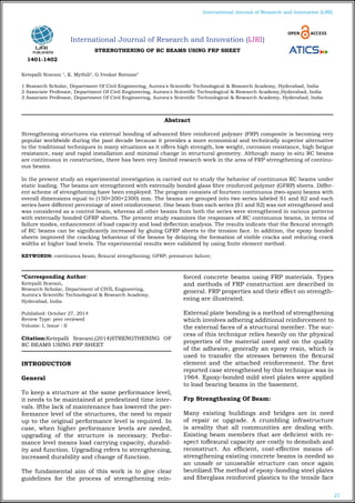
STRENGTHENING OF RC BEAMS USING FRP SHEET
Ketepalli Sravani 1
, K. Mythili2
, G.Venkat Ratnam3
1 Research Scholar, Department Of Civil Engineering, Aurora's Scientific Technological & Research Academy, Hyderabad, India
2 Associate Professor, Department Of Civil Engineering, Aurora's Scientific Technological & Research Academy,Hyderabad, India
3 Associate Professor, Department Of Civil Engineering, Aurora's Scientific Technological & Research Academy, Hyderabad, India
*Corresponding Author:
Ketepalli Sravani,
Research Scholar, Department of CIVIL Engineering,
Aurora's Scientific Technological & Research Academy,
Hyderabad, India
Published: October 27, 2014
Review Type: peer reviewed
Volume: I, Issue : II
Citation:Ketepalli Sravani,(2014)STRENGTHENING OF
RC BEAMS USING FRP SHEET
INTRODUCTION
General
To keep a structure at the same performance level,
it needs to be maintained at predestined time inter-
vals. Ifthe lack of maintenance has lowered the per-
formance level of the structures, the need to repair
up to the original performance level is required. In
case, when higher performance levels are needed,
upgrading of the structure is necessary. Perfor-
mance level means load carrying capacity, durabil-
ity and function. Upgrading refers to strengthening,
increased durability and change of function.
The fundamental aim of this work is to give clear
guidelines for the process of strengthening rein-
forced concrete beams using FRP materials. Types
and methods of FRP construction are described in
general. FRP properties and their effect on strength-
ening are illustrated.
External plate bonding is a method of strengthening
which involves adhering additional reinforcement to
the external faces of a structural member. The suc-
cess of this technique relies heavily on the physical
properties of the material used and on the quality
of the adhesive, generally an epoxy resin, which is
used to transfer the stresses between the flexural
element and the attached reinforcement. The first
reported case strengthened by this technique was in
1964. Epoxy-bonded mild steel plates were applied
to load bearing beams in the basement.
Frp Strengthening Of Beam:
Many existing buildings and bridges are in need
of repair or upgrade. A crumbling infrastructure
is areality that all communities are dealing with.
Existing beam members that are deficient with re-
spect toflexural capacity are costly to demolish and
reconstruct. An efficient, cost-effective means of-
strengthening existing concrete beams is needed so
an unsafe or unuseable structure can once again
beutilized.The method of epoxy-bonding steel plates
and fiberglass reinforced plastics to the tensile face
Abstract
Strengthening structures via external bonding of advanced fibre reinforced polymer (FRP) composite is becoming very
popular worldwide during the past decade because it provides a more economical and technically superior alternative
to the traditional techniques in many situations as it offers high strength, low weight, corrosion resistance, high fatigue
resistance, easy and rapid installation and minimal change in structural geometry. Although many in-situ RC beams
are continuous in construction, there has been very limited research work in the area of FRP strengthening of continu-
ous beams.
In the present study an experimental investigation is carried out to study the behavior of continuous RC beams under
static loading. The beams are strengthened with externally bonded glass fibre reinforced polymer (GFRP) sheets. Differ-
ent scheme of strengthening have been employed. The program consists of fourteen continuous (two-span) beams with
overall dimensions equal to (150×200×2300) mm. The beams are grouped into two series labeled S1 and S2 and each
series have different percentage of steel reinforcement. One beam from each series (S1 and S2) was not strengthened and
was considered as a control beam, whereas all other beams from both the series were strengthened in various patterns
with externally bonded GFRP sheets. The present study examines the responses of RC continuous beams, in terms of
failure modes, enhancement of load capacity and load deflection analysis. The results indicate that the flexural strength
of RC beams can be significantly increased by gluing GFRP sheets to the tension face. In addition, the epoxy bonded
sheets improved the cracking behaviour of the beams by delaying the formation of visible cracks and reducing crack
widths at higher load levels. The experimental results were validated by using finite element method.
KEYWORDS: continuous beam; flexural strengthening; GFRP; premature failure;
1401-1402
2. 28
International Journal of Research and Innovation (IJRI)
ofreinforced concrete beams has been studied ex-
tensively as a method to strengthen existing rein-
forcedconcrete structures. Experimental results
have proven that these techniques can be an effec-
tive means ofincreasing a beam’s flexural capacity
and stiffness. However, a problem that has been
encounteredduring the testing of reinforced beams
with epoxy-bonded plates is separation of the plate
from the beamat the plate termination prior to con-
crete compression failure. Furthermore, there is
some question as tothe loss of the ductile failure
mode usually associated with reinforced concrete
failure when carbon fibersheets and plates are used
for external reinforcement. The use of expansion
anchors has been examinedas a method of elimi-
nating epoxy-bonded plate tear off at termination.
Bonding of steel and fiber-reinforced plastics is the
most popular means of reinforcing existingconcrete
beams. However, applying epoxy can be a delicate
process requiring near perfect workingconditions.
The beam must be properly prepared for epoxy ap-
plication (smooth, flat, sandblasted, dustfree,clean
surface), and the thickness of the epoxy layer must
be uniform. Perfect conditions are not thenorm
when one is working in the field. This procedure can
be successful, but the quality controlmeasures can
be extreme. A solution to this problem is to take
advantage of the fact that bolts have beensuccessful
in stopping plate tear-off, and go one step further
and use anchor bolts as the main system ofanchor-
ing supplemental external steel reinforcement to the
beam. This method can be used underfrequently
encountered field conditions since the work envi-
ronment need not be ideal and prep work formount-
ing the reinforcement is minimal (aside from drilling
holes into the flexural member).
In the 1980s, fiber reinforced polymer (FRP) materi-
als began being used in civil engineering applica-
tions. The external strengthening of reinforced con-
crete members was an ideal use for preformed FRP
strips, which are lighter and easier to install than
steel strips. FRP strips do not rust when exposed
to moist environments as do steel strips. Currently
FRP strips are bonded to the concrete surface in the
same manner as the steel strips, and the concrete
substrate requires similar preparation as it would
for the bonding of a steel plate. The adhesive layer
between the concrete and strip can present prob-
lems for the behaviour of the strengthened flexural
member. Peeling stresses are induced in the ends of
the strip, which tend to pull the strip away from the
concrete. If these peeling stresses are larger than
the strength of the adhesive, the strip will peel away
from the beam suddenly. This results in the beam
losing the increase in strength provided by the strip,
and may cause a sudden and catastrophic failure.
Flexural members with attached steel strips often
have large anchor bolts on the ends of the strips.
These anchor bolts are provided to keep the steel
plate from falling and damaging people or prop-
erty in case the adhesive layer fails. Recently end
anchorages have been examined for use with FRP
strips as well.
Many researchers have been argued that the bond
is significantly affected by surface preparation and
general concrete quality, the degree and type of
external anchorage was found to be important in
maintaining the composite behaviour. This moti-
vates researches to find a more sustainable method
to bond CFRP and GFRP laminates with concrete
substrate using mechanical techniques.
A method of flexural strengthening reinforced con-
crete members with mechanically steel bolts is de-
veloped in this research study instead of an adhe-
sive to attach a specially designed FRP strip to the
concrete. This new technique has a potentially fast-
er installation time and a potentially more ductile
failure structural response than the sudden failure
of conventional bonded method with epoxy.
Fibre-Reinforced Plastic (FRP):
(also fibre-reinforced polymer) is a composite mate-
rial made of a polymer matrix reinforced with fibres.
The fibres are usually glass, carbon, basalt orara-
mid, although other fibres such as paper or wood or
asbestos have been sometimes used. The polymer
is usually an epoxy, vinyl ester or polyester thermo-
setting plastic, andphenol formaldehyde resins are
still in use.
Fibre Types:
Different types of fibres can be used in manufactur-
ing the FRP materials such as the following (Kend-
all, 1999):
E-Glass:
The most common reinforcing fibre is E-Glass,
which derives its name from its electrical resist-
ance. E-glass is available in a variety of forms such
as continuous rovings, woven rovings, stitched fab-
rics, unidirectional tapes and chopped fibre mats
or Chopped Strand Mat (CSM) as it is commonly
known. The fibre is very economical and of moder-
ate strength but low modulus (stiffness).
C, R and S Glass:
C glass is a chemical resistant grade mainly used
in the production of surface tissues to protect the
surface of a laminate. R glass and S glass are high
strength grades. Aramid Aramid, or Polyaramid fi-
bres such as Kevlar 49 are man-made organic fibres
offering very high tensile strengths and low density.
Aramid fabrics are very soft and easy to handle.
Carbon:
Carbon fibre is the most expensive of the more
common reinforcements, but due to its very high
strength and stiffness it is the most commonly used
fibre.
3. 29
International Journal of Research and Innovation (IJRI)
Advantages Of Fibre-Reinforced Plastics:
Fibreglass and other fibre-reinforced plastics (FRP),
such as carbon fibre and Kevlar, have many advan-
tages:
Low weight: even the cheapest fibreglass is much
less dense and therefore lighter than the equivalent
volume of steel or aluminium.
Mechanical strength: fibreglass is so strong and
stiff for its weight, it can out-perform most other
materials including steel, aluminium and timber.
Carbon-fibre and Kevlar can be used to make items
even lighter. The strength and stiffness per weight
of these exotic materials exceeds that of all known
materials.
High impact strength: in contrast to most metals,
fibreglass does not change shape even when it is
ruptured.
Resiliance: fibreglass products have a hard finish.
The gelcoat which covers and colours finished fi-
breglass products can be tailored to provide greater
hardness or more resiliance.
Formability: fibreglass can be moulded to almost
any desired shape. We can create or copy most
shapes with ease. Fibreglass moulds are cheap to
make compared with those for metal or plastic. It
is quite easy to change the weight and strength of a
product without having to make a new mould.
Chemical resistance: fibreglass is minimally re-
active, making it ideal as a protective covering for
surfaces where chemical spillages might occur. It
is useful in the construction of tanks, hoods, cov-
ers, pipes, ducts and other structures in the paper,
chemical, water treatment and petroleum indus-
tries.
Corrosion resistance: unlike metal, fibreglass does
not rust away and it can be used to make long-last-
ing structures.
Weatherproof: the chemical and corrosion resist-
ance of fibreglass combined with the gelcoat finish
on most products make fibreglass ideal for using
outdoors. If necessary, chemicals can be added to
provide additional protection against UV light.
Electrically insulating: for those working in the
power industry, materials such as fibreglass which
do not conduct electricity are essential for safety.
However, if required, we can adapt our fibreglass to
become electrically conductive.
Thermally insulating: fibreglass is not only long
lasting but maintains its temperature, thus reduc-
ing heating and cooling costs. The fibreglass sur-
face remains comfortable to touch, being neither
hot nor cold.
Fire resistance: by the addition of special addi-
tives, fibreglass can be made fire resistant to meet
most fire codes. The resins used conform to BS476
or ASTM-E-84.
Low thermal expansion: minimally affected by
changes in external temperature, fibreglass is ideal
for situations where temperatures fluctuate.
Anti-magnetic, no sparks: making it super safe for
the power industry, fibreglass has no magnetic field
and resists electrical sparks.
Low maintenance: once installed, fibreglass prod-
ucts require minimal maintenance.
Durable custom colours: fibreglass can be col-
oured, shiny or dull. We can even add patterns if
you wish. Your production costs are reduced as our
gelcoated products don't need further painting or
finishing. With care, the gelcoat finish on our auto-
motive parts can last for up to 20 years.
Long life: our fibreglass products are built to last.
Fibreglass has high resistance to fatigue and has
shown excellent durability over the last 50 years.
Structural Applications Of FRP:
FRP can be applied to strengthen the beams, col-
umns, and slabs of buildings and bridges. It is pos-
sible to increase the strength of structural members
even after they have been severely damaged due to
loading conditions. In the case of damaged rein-
forced concrete members, this would first require
the repair of the member by removing loose debris
and filling in cavities and cracks with mortar or
epoxy resin. Once the member is repaired, strength-
ening can be achieved through wet, hand lay-up of
impregnating the fibre sheets with epoxy resin then
applying them to the cleaned and prepared surfaces
of the member.
Two techniques are typically adopted for the
strengthening of beams, relating to the strength en-
hancement desired: flexural strengthening or shear
strengthening. In many cases it may be necessary to
provide both strength enhancements. For the flex-
ural strengthening of a beam, FRP sheets or plates
are applied to the tension face of the member (the
bottom face for a simply supported member with
applied top loading or gravity loading). Principal
tensile fibres are oriented in the beam longitudinal
axis, similar to its internal flexural steel reinforce-
ment. This increases the beam strength and its stiff-
ness (load required to cause unit deflection), how-
ever decreases the deflection capacity and ductility.
Disadvantages Of FRP:
The main disadvantage of externally strengthening
structures with fibre composite materials is the risk
of fire, vandalism or accidental damage, unless the
strengthening is protected. A particular concern for
bridges over roads is the risk of soffit reinforcement
4. 30
International Journal of Research and Innovation (IJRI)
being hit by over-height vehicles.
A perceived disadvantage of using FRP for strength-
ening is the relatively high cost of the materials.
However, comparisons should be made on the basis
of the complete strengthening exercise; in certain
cases the costs can be less than that of steel plate
bonding. A disadvantage in the eyes of many clients
will be the lack of experience of the techniques and
suitably qualified staff to carry out the work. Final-
ly, a significant disadvantage is the lack of accepted
design standards.
Experimental Study
Experimental Program:
A total of six rectangular beams were tested to find
the effectiveness of the strengthening process us-
ing GFRP laminates. Two beams were tested as con-
trolled beams for flexure, while the remaining four
beams were strengthened using GFRP mats and
tested with the goal of increasing their flexural ca-
pacities. The concept is based on the fact that the
force developed in the GFRP mat is due to contact
between the materials because of the bond which is
responsible for the increase in flexural capacities.
This paper provides information regarding
(i)Deformation characteristics of load versus deflec-
tion
(ii)Ductile capacity of composite beams.
Casting Of Specimen:
For conducting experiment, the proportion of 1: 1.9:
3.91 is taken for cement, fine aggregate and course
aggregate. The mixing is done by using concrete
mixture. The beams are cured for 28 days. For each
beam six concrete cube specimens were made at the
time of casting and were kept for curing. The uni-
axial compressive tests on produced concrete (150
× 150 × 150 mm concrete cube) were performed and
the average concrete compressive strength (fcu) af-
ter 28 days for each beam is shown in tables.
Descrip-
tion
Cement
Sand (Fine
Aggregate)
Course
Aggregate Water
Mix Pro-
portion
(by weight)
1 1.9 3.91 0.51
Quantities
of materi-
als
213 404.7 832.83 108.63
Materials For Casting:
Cement :
Portland Slag Cement (PSC) (Brand: Konark) is used
for the experiment. It is tested forits physical prop-
erties in accordance with Indian Standard specifica-
tions. It is having a specific gravity of 2.96.
(i)Specific gravity : 2.96
(ii)Normal Consistency : 32%
(iii)Setting Times : Initial : 105 minutes Final : 535
minutes.
(iv)Soundness : 2 mm expansion
(v)Fineness : 1 gm retained in 90 micron sieve.
Fine Aggregate:
The fine aggregate passing through 4.75 mm sieve
and having a specific gravity of 2.67are used. The
grading zone of fine aggregate is zone III as per In-
dian Standard specifications.
Coarse Aggregate:
The coarse aggregates of two grades are used one
retained on 10 mm size sieve and
another grade contained aggregates retained on 20
mm sieve. It is having a specific gravity of 2.72.
Water:
Ordinary tap water is used for concrete mixing in
all the mix.
Test Specimens:
All the six cast test specimens are rectangular RC
beamsof cross section 220mmx250mm and length
2000mm.six numbers of beams were tested for flex-
ure. It consists of two numbers of 10mmdiameter
and one number of 12mm diameter bars whichare
used in compression and tension sides. The ver-
ticalstirrups are provided with 6mm diameter bar
at aspacing of 225mm c/c as shown in Figure.
Thesebeams were designed to fail by flexure. Out
of sixbeams, two were used as control beams and
remainingfour were strengthened using GFRP mats.
The designmix adopted for all beams were 1: 1.9:
3.91 and watercement ratio of 0.51. The test speci-
mens were cured for28 days and they were tested.
5. 31
International Journal of Research and Innovation (IJRI)
GFRP Composites:
E-Glass fiber in the form of woven fabric of600gm/
sq.m is used for strengthening purposes. Forbond-
ing these fabric mats with RC beams, 45% byweight
of general purpose Iso resin is used.
Strengthening Configurations:
Two strengthening configurations were adopted us-
ingGFRP mats for flexure beams which are shown
in figure. Externally they are wrapped by a (i) Sin-
glelayer at two vertical sides, and tension bottom
face(GFRP1) and (ii) Double layer at two vertical
sides andtension bottom face(GFRP2).
ReinforcementOf Beam
Strengthening Of Gfrp Beams
Testing Arrangements:
The beams were tested in a steel loading frame ca-
pacityof 500kN. The arrangement is shown in Fig-
ure. Forgetting moment effect of the beam, an ex-
perimentalsetup has been arranged as shown in
Figure. Thesupport points were provided with a
hinge support atboth ends of steel rod welded to the
base plate. The loadwas applied by means of 500kN
capacity hydraulic jackpowered by hand operat-
ed hydraulic pump. The systematic Figure clearly
shows the loadingarrangement for getting the mo-
ment effect of the beam.
Deflections measured at important points. Three
number of dial gauges have used for recording the
deflection ofthe beams. One dial gauge has placed
just below thecenter of the beam and the remaining
two dial gaugeshave placed just near the middle of
the beam to measuredeflections as shown in Figure.
The cracking patternwas also marked by drawing
lines along the crack. The tests are carried out till
the ultimate failure.
FABRICATION OF GFRP PLATE:
There are two basic processes for moulding: hand
lay-up and spray-up. The hand lay-up process is
the oldest and simplest fabrication method. The
process is most common in FRP marine construc-
tion. In hand lay-up process, liquid resin is placed
along with FRP against finished surface. Chemi-
cal reaction of the resin hardens the material to a
strong light weight product. The resin serves as the
matrix for glass fiber as concrete acts for the steel
reinforcing rods.
The following constituent materials were used for
fabricating plates:
1.Glass Fiber
2.Epoxy as resin
3.Diamine as hardener as (catalyst)
4.Polyvinyl alcohol as a releasing agent
A plastic sheet was kept on the plywood platform
Loading frame
Loading System
Shear Force Diagram
6. 32
International Journal of Research and Innovation (IJRI)
Bending Moment Diagram
Flexural Zone
and a thin film of polyvinyl alcohol was applied as a
releasing agent by the use of spray gun. Laminating
starts with the application of a gel coat (epoxy and
hardener) deposited in the mould by brush, whose
main purpose was to provide a smooth external sur-
face and to protect fibers from direct exposure from
the environment. Steel roller was applied to remove
the air bubbles. Layers of reinforcement were ap-
plied and gel coat was applied by brush. Process
of hand lay-up is the continuation of the above
process before gel coat is hardened. Again a plas-
tic sheet was applied by applying polyvinyl alcohol
inside the sheet as releasing agent. Then a heavy
flat metal rigid platform was kept top of the plate for
compressing purpose. The plates were left for mini-
mum 48 hours before transported and cut to exact
shape for testing.
Determination Of Ultimate Stress, Ultimate Laod
And Young’smodulus:
The ultimate stress, ultimate load and young’s mod-
ulus was determined experimentally by performing
unidirectional tensile test on the specimens cut in
longitudinal and transverse direction. The speci-
mens were cut from the plates by diamond cutter
or by hex saw. After cutting by hex saw, it was pol-
ished in the polishing machine.
For measuring the young’s modulus, the specimen
is loaded in INSTRON 1195 universal tensile test
machine to failure with a recommended rate of ex-
tension. Specimens were gripped in the upper jaw
first and then gripped in the movable lower jaw.
Gripping of the specimen should be proper to pre-
vent slippage. Here, it is taken as 50 mm from each
side. Initially, the stain is kept zero. The load as well
as extension was recorded digitally with the help of
the load cell and an extensometer respectively. From
these data, stress versus stain graph was plotted,
the initial slope of which gives the Young’s modulus.
The ultimate stress and the ultimate load were
Bonding epoxy
Universal Testing Machine
obtained at the failure of the specimen. The average
value of each layer of the specimens is given.
TESTING OF BEAMS:
All the six beams are tested one by one. All of them
are tested in the above arrangement. The gradual
increase in load and the deformation in the dial
gauge reading are taken throughout the test. The
load at which the first visible crack is developed is
recorded as cracking load. Then the load is applied
till the ultimate failure of the beam. The deflections
at midpoint of each span are taken for all beams
with and without GFRP and are recorded with re-
spect to increase of load. The data furnished in this
chapter have been interpreted and discussed in the
next chapter to obtain a conclusion.
7. 33
International Journal of Research and Innovation (IJRI)
Test Resultsand Discussions
Failure Modes Of Beams:
Peeling Failure:
The application of the GFRP fabrics to the soffit of
the concrete beam introduces shear transfer to the
concrete/epoxy interface. At the termination of the
GFRP fabric, a change in stiffness and discontinuity
of beam curvature creates a stress concentration in
the concrete, often initiating cracks that can lead
to debonding.
Based on the experimental observations, the mech-
anism of peeling failure can be described in
the following sequences:
1) uniformly spaced cracks developed in the con-
stant bending moment zone and some small cracks
in the shear span
2) as a result of shear stress and normal stress con-
centrations at the GFRP fabric end, the concrete
rupture strength was exceeded at this point and a
crack formed near the fabric end. This end Debond-
ing propagation to the CFRP fabric endDebond-
ingstarted here Loading point crack widened with
increasing load and propagated to the level of the
internal steel reinforcement
3) individual concrete cover blocks were formed be-
tween two adjacent cracks;
4) the end concrete cover block peeled away as the
load increased
5) This process continued sequentially for the rest
of the blocks
Due to the dowel action of the stirrups, the weakest
plane forms right under the longitudinal steel rein-
forcement, thus, the peeling failure always started
from the end of the plates and propagated along the
concrete cover parallel to the longitudinal steel re-
inforcing bars.
Debonding Failure
The beams with FRP fabric extending all the way to
the support are subjected to lower stress concentra-
tions at the FRP cutoff points and shear crack may
not developed at these points. On the other hand,
within the shear span, the shear stress concentra-
tion around the flexural or shear crack mouth dis-
placements may also lead to the local debonding of
the fabric along concrete-fabric interface.
Flexural cracks, located in regions of the beam with
large moment, can initiate interfacial fracture which
propagates between the concrete and FRP interface.
Crack mouths located in regions of the beam with
mixed shear and moments can subject an interfa-
cial crack to mixed mode loading.
For beam with a long fabric covering almost the
whole length of span, the debonding started at one
of the flexural cracks in vicinity of the point load.
The debonding propagated towards the sheet end
until total delamination occurred.
In general, peeling of the concrete cover at the level of
internal steel reinforcement occurred in beams with
shorter fabric length where significant shear cracks
were formed, indicating that significant stress con-
centration can occur at the sheet anchorage zone.
Debonding failure between FRP fabric and concrete
occurred due to susceptibility of the interface rela-
tive to vertical displacements of shear cracks in the
concrete beam.
BEAM SHEAR FAILURE MODES:
Three distinct modes of shear failure are observed,
which describe the manner inwhich concrete fails:
• Diagonal tension failure
• Shear compression failure
• Shear tension failure
DIAGONAL TENSION FAILURE:
This type of failure is usually a flexure-shear crack.
The diagonal crack starts from the last flexural
crack at mid span, where it follows direction of the
bond reinforcing steel and the concrete at the sup-
port. After that, few more diagonal cracks develop
with further load, the tension crack will extend
gradually until it reaches its critical point where it
will fail without warning. This type of shear failure
is always in the shear-span when the a/d ratio is in
the range of 2.5 to 6. Such beams fail either in shear
or in flexure.
Failure Plane
SHEAR COMPRESSION FAILURE:
This type of failure is common in short beams with
a/d ratio between 1 and 2.5. It’s called a web shear
crack, it’s crushing the concrete in the compression
zone due to vertical compressive stresses developed
in the vicinity of the load.
Compression Failure
SHEAR TENSION FAILURE:
This type of failure is also common in short beams
and it is similar to diagonal tension failure. First
8. 34
International Journal of Research and Innovation (IJRI)
we can see a shear crack that is similar to the di-
agonal crack that goes through the beam; the crack
extends toward the longitudinal reinforcement and
then propagates along the reinforcement that re-
sults in the failure of the beam.
Shear Torsion Failure
RESULTS OF EXPERIMENTS:
FAILURE PATTERN OF CONTROL BEAM:
The beam was so designed that it fails by flexure.
The beam was tested up to 42kN. The yield of steel
was found at 37kN. With further increase in the
load, regularly spaced flexure and shear cracks were
observed and they extended from the bottom of the
specimen towards the top fiber as shown in figure.
Failure Pattern OfControl Beam
FAILURE PATTERN FOR STRENGTHENING
BEAM:
The beam was strengthened with one layer of GFRP1
laminate on the bottom face and two vertical sides
completely. The ultimate load carrying capacity of
the beam was 66kN. The yield load was 57kN. The
load carrying capacity of this beam was increased
by 55%when compared to control beam as shown in
Figure. The failure was initiated by the stretching of
fiber wrap at the bottom in the flexure zone followed
by the crushing of concrete in compression zone as
shown in figure.
Failure Pattern Of Single Layer GFRP1 Beam
Failure Pattern OfDouble Layer GFRP2Beam
The beam was strengthened with two layers of
GFRP2 laminate on the bottom face and two verti-
cal sides completely. The ultimate load carrying ca-
pacity of the beam was 92kN. The yield load was
78kN. The load carrying capacity of this beam was
increased by 120% when compared to control beam
as shown in Figure. The failure was initiated by the
stretching of fibre wrap at the bottom in the flexure
zone followed by the crushing of concrete in com-
pression zone as shown in Figure.
Designation
of Beams
Failure Mode Pu(KN)
λ=Pu(strengthened beam)
Pu(Control beam)
Control beam Flexure failure 42 1
Single layer
GFRP1
Debonding failure
without concrete
cover
66 1.57
Double layer
GFRP2
Tensile rupture 92 2.19
LOAD DEFLECTION AND LOAD CARRYING
CAPACITY:
The GFRP strengthened beams and the control
beams are tested to find out their ultimate load
carrying capacity. The deflection of each beam un-
der the load point i.e. at the midpoint of each span
position is analyzed. Mid-span deflections of each
strengthened beam are compared with the control
beam. It is noted that the behavior of the flexure
deficient beams when bonded with GFRP sheets are
better than the control beams. The mid-span deflec-
tions of the beams are lower when bonded externally
with GFRP sheets. The stiffness of the strengthened
beams was higher than that of the control beams.
Increasing the numbers of GFRP layers generally
reduced the mid span deflection and increased the
beam stiffness for the same value of applied load.
The use of GFRP sheet had effect in delaying the
growth of crack formation.
9. 35
International Journal of Research and Innovation (IJRI)
Ductility:
A qualitative measure of ductility has to be with
reference to a load – deformation response. A duc-
tileresponse would be reflected in the deformation-
increasing at nearly constant load. The ratio of
theultimate deformation to the deformation at the-
beginning of the horizontal path can give a measure
ofductility.
Ductility has generally been measured by a ratio
calledthe ductility index or factor (μ). The ductil-
ity index isusually expressed as a ratio of rotation
(θ), curvature(φ), deflection (displacement) (M), and
absorbed energy(E) at failure (peak load) divided by
the correspondingproperty when the steel starts
yielding. In the presentstudy, ductility was obtained
based on displacement and absorbed energy meth-
ods.
Displacement Ductility:
Figure shows the response of a strengthened RC-
beam. Point A corresponds to initial concrete
cracking,point B to the first steel yielding, and point
C to failure.Based on Figure , the displacement duc-
tility index is defined by Eq. Where Mu is the mid
span deflection at ultimate beamload and My is the
mid span deflection at yielding loadof the tensile
steel reinforcement at the central support.
Table shows the experimental values of (Mu),
(My),the displacement ductility index value of (μM),
and percentage of increase of displacement ductility
in theBC. It can be seen that increasing the num-
ber of GFRPsheet layers led to increased mid span
deflection at yieldload level and ultimate load level.
Finite Element Analysis
Finite element method (FEM) is a numerical meth-
od for solving a differential or integral equation. It
has been applied to a number of physical problems,
where the governing differential equations are avail-
able. The method essentially consists of assuming
the piecewise continuous function for the solution
and obtaining the parameters of the functions in a
manner that reduces the error in the solution.
Formulation:
The governing equation for beam is given in Equa-
tion 5.1.
d2
y
M = EI
d x2
The displacement field v(x) assumed for the beam
element should be such that it takes on the
values of deflection and the slope at either end as
given by the nodal values
The v(x) can be given by,
v(x) = c0 + c1x + c2 x2
+c3x3
Type Of
Beam
(∆u) (∆y) (µ∆) Increase (Eu) (Ey) (µE) Increase
overthe
control
beam(%)
overthe
control
beam(%)
(mm) (mm) By
Eq.(1)
kN kN By
Eq.(2)
Control
beam
20 8 2.5 - 42 37 1.13 -
Sin-
glelayr
GFRP1
29 9.5 3.05 22 66 57 1.16 3
Double
layer
GFRP2
38 11 3.45 38 92 78 1.18 5
In solving the differential equations through integra-
tion, there will be constants of integration that must
be evaluated by using the boundary and continu-
ity conditions. The variables whose values are to be
determined are approximated by piecewise continu-
ous polynomials. The coefficients of these polynomi-
als are obtained by minimizing the total potential
energy of the system. In FEM, usually, these coef-
ficients are expressed in terms of unknown values
of primary variables. Thus, if an element has got n
nodes, the displacement field u can be approxi
Where ui are the nodal displacements in x-direction
and Ni are the shape functions, which are functions
of coordinates.
Shape functions or interpolation functions Ni are
used in the finite element analysis to interpolate the
nodal displacements of any element to any point
within each element.
The beam element has modulus of elasticity E, mo-
ment of inertia I, and length L. Each beam element
has two nodes and is assumed to be horizontal as
shown in Figure. The element stiffness matrix is giv-
en by the following matrix, assuming axial deforma-
tion is neglected.
VALIDATION OF EXPERIMENTAL VALUE:
In the experimental work, the tested beams consist
of two spans of each 1000 mm as shown in Figure
is discritized as shown in Figure.
Test Beam
Finite Element Model
10. 36
International Journal of Research and Innovation (IJRI)
Beam Element Forces
The following sign convention is considered for the
deflection calculation.
(a)x is +ve towards right
(b)y is +ve upwards
(c)Anticlockwise slopes are +ve
(d)Sagging BM are +ve
Three element mesh is taken as shown in Figure.
Subdividing the span AD into three elements with
a node at the load point has the advantage that,
the nodal forces can be specified very easily. The
meshing has also ensured that all elements are of
uniform size, for easy hand calculation. Following
the standard procedure, the global stiffness matrix
and force vector is obtained as below,
{K}8x8
{U}8x1
= {F}8x1
Since there are four nodes and two d.o.f. per node,
the global stiffness matrix is of size (8x8) and {F} is
a column vector of size (8×1). The boundary condi-
tions stipulate that the vertical deflection be zero at
node 2 and 4.
Boundary conditions are the known values of de-
flection and slope at specified values of x. Here the
following boundary conditions are used for the ex-
act analysis of the beam.
At x =L/2; y=0
At x= 3L/2; y= 0
Thus reduced set of equations involving unknown
nodal d.o.f. is obtained in matrix form as,
{f}6x1
= [k]6x6
[u]6x1
Solving the Equation, the nodal displacement is
found out.
The Numerical and Experimental results are found
to be very near. The trend of the loads varying with
the deflection presents that the linear elastic state
exits in the structure, when the loads are equivalent
to about 48 KN.
CONCLUSIONS
Based on the Investigation the Following Conclu-
sions were made:
1.The provision in the ACI code can be used as
guidelines for the use of FRP in the repair and reha-
bilitation of structures.
2.Maximum percentage of increase in ultimate
strength was 55% for single layer GFRP and 120%
for double layer GFRP.
3.By the use of GFRP wrapping in the beams, the
initial cracks are formed at higher loads than in
their respective control beams. This shows that the
use of GFRP wrapping is more efficient in the case
of strengthening of shear and flexure.
4.The increase in the strength of the beam depends
upon the increasing number of laminates provided
to the beam.
5.The presence of GFRP laminate beam inhibits the
development of the diagonal cracks. There is a sig-
nificant difference in the load which causes this ini-
tial crack. The load –deflection behaviour was better
for beams retrofitted with GFRP laminate beams.
6.For the beams laminated with GFRP flexural fail-
ure was more prominent than shear failure.
7.When compared to control beams, displacement
ductility index of the strengthened beams is in-
creased by 22%, and 38% for Single layer of GFRP1
and Double layer of GFRP2 respectively.
8.The energy ductility index is increased by 3%
and 5% for Single layer of GFRP1 and Double layer
of GFRP2 respectively, when compared to control
beams.
9.In lower range of load values the deflection ob-
tained using Finite Element models are in good
agreement with the experimental results. For higher
load values there is a deviation with the experimen-
tal results because linear FEM has been adopted.
Scope Of The Future Work
It promises a great scope for future studies. Follow-
ing areas are considered for future research:
a.Experimental study of continuous beams with
opening
b.Non linear analysis of RC continuous beam
c.FEM modeling of unanchored U-wrap
d.FEM modeling of anchored U-wrap
11. 37
International Journal of Research and Innovation (IJRI)
REFERENCES:
[1] ACI Committee 440, “Starte-of-the-art report on fiber
reinforced plastic reinforcement for concrete structures”,
Report ACI 440R-96, USA: American Concrete Institute,
1996.
[2] Aiello MA, Valente L, and Rizzo A, “Moment redistribu-
tion in continuous reinforced concrete beams strength-
ened with carbon fiber-reinforced polymer laminates”,
Mechanicsof Composite Materials, vol. 43, pp. 453-466,
2007.
[3] Aiello MA, and Ombres L, “Cracking and deformability
analysis of reinforced concrete beams strengthened with
externally bonded carbon fiber reinforced polymer sheet”,
ASCEJournal of Materials in Civil Engineering, vol. 16,
No. 5, pp.292-399,2004.
[4] Akbarzadeh H, and Maghsoudi AA, “Experimental
and analytical investigation of reinforced high strength
concrete continuous beams strengthened with fiber rein-
forced polymer”, Materials and Design, vol. 31, pp. 1130-
1147, 2010.
[5] Arduini M, and Nanni A, “Behaviour of pre-cracked R.
C. beams strengthened with carbon FRP sheets”, ASCE
Journal of Composites for Construction, vol. 1, No. 2, pp.
63-70, 1997.
[6] Ashour AF, El-Refaie SA, and Garrity SW, “Flexural
strengthening of RC continuous beams using CFRP lam-
inates”, Cement and Concrete Composites, vol. 26, pp.
765-775, 2003.
[7] Bank LC, and Arora D, “Analysis of RC beams strength-
ened with mechanically fastened FRP (MF-FRP) strips”,
Composite Structures, vol. 79, pp. 180–191, 2006.
[8] Bousselham A and Chaallal O, “Behavior of reinforced
concrete T-beams strengthened in shear with carbon fiber
reinforced polymer - an experimental study”, ACI Struc-
tural Journal, vol. 103, pp. 339–347, 2006.
[9] Brosens K, and Gemert D, “Anchoring stresses be-
tween concrete and carbon fiber reinforced laminates”,
Non-metallic (FRP) Reinforcement for Concrete Struc-
tures, Proc.of 3rd International Symposium, Sapporo, Ja-
pan, pp. 271–278, 1997.
[10] Ceroni F, “Experimental performances of RC
beams strengthened with FRP materials”,Construction
and Building Materials, vol. 24, pp. 1547-1559, 2010.
[11] Chahrour A, and Soudki K, “Flexural response of re-
inforced concrete beams strengthened with end-anchored
partially bonded carbon fiber-reinforced polymer strips”,
Journal ofComposites for Construction ASCE, vol. 9(2),
pp. 170–177, 2005.
[12] Concrete Society, “Design guidance for strengthen-
ing concrete structures using fibre composite materials”,
Report No. 55, 71p, 2000.
[13] El-Refaie SA, Ashour AF, and Garrity SW, “CFRP
strengthened continuous concrete beams”, Proceedings of
the ICE - Structures and Buildings, pp. 395 - 404, 2003.
[14] El-Refaie SA, Ashour AF, and Garrity SW, “Sag-
ging and hogging strengthening of continuous reinforced
concrete beams using carbon fibre-reinforced polymer
sheets”, ACIStructural Journal, vol. 100, pp. 446-453,
2003.
[15] El-Refaie SA, Ashour AF, and Garrity SW, “Sagging
strengthening of continuous reinforced concrete beams
using carbon fibre sheets”, The 11th BCA Annual Con-
ferenceon Higher Education and the Concrete Industry,
Manchester, UK, pp. 281–292, 3–4 July2001.
[16] El-Refaie SA, Ashour AF, and Garrity SW, “Strength-
ening of reinforced concrete continuous beams with CFRP
composites”, The International Conference on Struc-
turalEngineering, Mechanics and Computation, Cape
Town, South Africa, 2–4. , pp.1591– 1598, April 2001.
[17] El-Refaie SA, Ashour AF, and Garrity SW, “Tests of
reinforced concrete continuous beams strengthened with
carbon fibre sheets”, The 10th BCA Annual Conference
onHigher Education and the Concrete Industry, Birming-
ham, UK, pp. 187–198, Jun 2000.
[18] Eshwar N, Nanni A, and Ibell TJ, “Performance of
two anchor systems of externally bonded fiber-reinforced
polymer laminates”, ACI Materials Journal, vol. 105(1),
pp. 72– 80, 2008.
[19] Galati D, and De Lorenzis L, “Effect of construction
details on the bond performance of NSM FRP bars in con-
crete”, Advances in Structural Engineering, vol. 12(5), pp.
683– 700, 2009.
[20] Garden HN, and Hollaway LC, “An experimental
study of the influence of plate end anchorage of carbon
fibre composite plates used to strengthen reinforced con-
crete beams”, Composite Structures, vol. 42, pp. 175–
188, 1998.
[21] Garden HN, and Hollaway LC, “An experimental
study of the influence of plate end anchorage of carbon
fibre composite plates used to strengthen reinforced con-
crete beams”, Composite Structures, vol. 42, pp. 175–
188, 1998.
[22] Grace NF, “Strengthening of negative moment region
of reinforced concrete beams using carbon fiber- rein-
forced polymer strips”, ACI Structural Journal, vol. 98,
No. 3, pp. 347-358, 2001.
[23] Grace NF, Sayed GA, and Saleh KR, “Strengthening
of continuous beams using fibre reinforced polymer lami-
nates”, American Concrete Institute, Farmington Hills,
Mich, pp. 647-657, 1999.
[24] Grace NF, Wael R, and Sayed AA, “Innovative tri-
axailly braided ductile FRP fabric for strengthening struc-
tures”, 7th International Symposium on Fiber Reinforce
Polymer for Reinforced Concrete Structures, ACI, Kansas
City, MO, 2005.
[25] Grace NF, Abdel-Sayed G, Soliman AK, and Saleh KR,
Strengthening of reinforced concrete beams using fibre
reinforced polymer (FRP) laminates”, ACI Structural Jour-
nal, vol. 96, No. 5, pp. 865-874, 1999.
[26] Grace NF, Soliman AK, Abdel-Sayed G, and Saleh
KR, “Strengthening of continuous beams using fibre re-
inforced polymer laminates”, Proceedings of 4th Inter-
nationalSymposium on Fibre Reinforced Polymer Rein-
forcements for Reinforced Concrete Structures, SP-188,
American Concrete Institute, Farmington Hills, Michigan,
USA,pp.647-657, 1999.
12. 38
International Journal of Research and Innovation (IJRI)
[27] Jumaat MZ, and Alam MA, “Experimental and nu-
merical analysis of end anchored steel plate and CFRP
laminate flexurally strengthened R. C. beams”, Interna-
tional Journal ofPhysical Sciences, vol. 5, pp. 132-144,
2010.
[28] Jumaat MZ, Rahman MM, and Rahman MA, “Review
on bonding techniques of CFRP in strengthening concrete
structures”, International Journal of the Physical Scienc-
es, vol. 6(15), pp. 3567-3575, 4 August. 2011.
[29] Kadhim, “Effect of CFRP Sheet Length on the Behav-
ior of HSC Continuous Beam”, Journal of Thermoplastic
composite materials, Vol. 00, 2011.
[30] Khalifa A, and Nanni A, “Improving shear capacity
of existing RC T-section beams using CFRP composites”,
Cement and Concrete Composites, vol. 22, pp. 165–174,
2000.
[31] Khalifa A, Tumialan G, Nanni A, and Belarbi A,
“Shear Strengthening of Continuous Reinforced Beams
Using Externally Bonded Carbon Fiber Reinforced Poly-
mer Sheets”,In: Fourth International Symposium on Fiber
Reinforced Polymer Reinforcement for Reinforced Con-
crete Structures, Baltimore, MD, American Concrete In-
stitute, pp. 995–1008, November 1999.
[32] Lamanna AJ, Bank LC, and Scott DW, “Flexural
strengthening of reinforced concrete beams using fasten-
ers and fiber-reinforced polymer strips”, ACI Structural
Journal, vol. 98(3), pp. 368–76, 2001.
[33] Lee TK, and Al-Mahaidi R, “An experimental investi-
gation on shear behaviour of RC T-beams strengthened
with CFRP using photogrammetry”, Composite Struc-
tures, vol. 82, pp. 185–193, 2008.
[34] Leung CKY, and Cao Q, “Development of strain hard-
ening permanent formwork for durable concrete struc-
tures”, Materials and Structures, vol. 43(7), pp. 993–
1007, 2009.
[35] Leung CKY, “Delamination failure in concrete beams
retrofitted with a bonded plate”,Journal of Materials in
Civil Engineering, vol. 13, pp. 106–113, 2001.
[36] Leung CKY, “FRP debonding from a concrete sub-
strate: Some recent findings against conventional belief”,
Cement and Concrete Composites, vol. 28, pp. 742–748,
2006.
[37] Maghsoudi AA, and Bengar H, “Moment redistribu-
tion and ductility of RHSC continuous beams strength-
ened with CFRP”, Turkish Journal of Engineering and
EnvironmentalSciences, vol. 33, pp. 45-59, 2009.
[38] Micelli F, Anniah RH, and Nanni A, “Strengthening
of short shear span reinforced concrete T joists with fiber
reinforced plastic composites”, Journal of Composites for-
Construction, vol. 6, pp. 264–271, 2002.
[39] Nguyen DM, Chan TK, and Cheong HK, “Brittle
failure and bond development length of CFRP-concrete
beams”, Journal of Composites for Construction, vol. 5(1),
pp. 12–17,2001.
[40] Niemitz CW, James R, and Berña SF, “Experimental
behavior of carbon fiber-reinforced polymer (CFRP) sheets
attached to concrete surfaces using CFRP anchors”, Jour-
nal ofComposites for Construction, vol. 12(2), pp. 185–
194, 2010.
[41] Obaidat YT, Susanne H, Ola D, Ghazi A, Yahia A,
“Retrofitting of reinforced concrete beams using compos-
ite laminates”, Construction and Building Materials, vol.
25, pp. 591-597, 2010.
[42] Oehlers DJ, Liu IST, and Seracino R, “Shear deforma-
tion debonding of adhesively bonded plates” Proc. Institu-
tion of Civil Engineers, vol. 158(1), pp. 77–84, 2005.
[43] Orton, SL, Jirsa JO, and Beyrak O, “Design consid-
erations of carbon fiber anchors.”Journal of Composites
for Construction, vol. 12(6), pp. 608–616, 2008.
[44] Pan JL, and Leung CKY, “Effect of concrete composi-
tion on FRP/concrete bond capacity.” Journal of Compos-
ites for Construction, vol. 11(6), pp. 611–618, 2007.
[45] Rahimi H, and Hutchinson A, “Concrete beams
strengthened with externally bonded FRP plates.” Jour-
nal of Composites for Construction, vol. 5(1), pp. 44–56,
2001.
[46] Ritchie PA, Thomas DA, Lu LW, and Connelly GM,
“External reinforcement of concrete beams using fiber re-
inforced plastic”, ACI Structural Journal, vol. 88(4), pp.
490– 500,1991.
[47] Smith ST, and Teng JG, “Debonding failures in FRP-
plated RC Beams with or without U strip end anchorage”,
Proc. FRP Composites in Civil Engineering, vol. 1, pp.
607–615, 2001.
[48] Panda KC, Bhattacharyya SK, and Barai SV, “Shear
behaviour of reinforced concrete T-beams with U-bond-
ed glass fibre reinforced plastic sheet”, Indian Concrete
Journal, vol. 84, pp. 61–71, 2010.
[49] Riyadh A, “Coupled flexural retrofitting of RC beams
using CFRP straps”, CompositeStructures, vol. 75, pp.
457-464, 2006.
[50] Ross CA, Jerome DM, Tedesco JW, and Hughes ML,
“Strengthening of reinforced concrete beams with exter-
nally bonded composite laminates”, ACI Structural Jour-
nal, vol. 96. No. 2, pp. 65-71, 1999.
[51] Sebastian WM, “Significance of mid-span de-bond-
ing failure in FRP-plated concrete beams”, ASCE Journal
of Structural Engineering, vol. 127, No. 7, pp.792-798,
2001.
[52] Sheikh SA, “Performance of concrete structures
retrofitted with fibre reinforced polymers”, Engineering
Structures, vol. 24, pp. 869-879, 2002.
[53] Smith ST, and Teng JG, “FRP-strengthened RC
beams I: Review of debonding strength models”, Engi-
neering Structures, vol. 24, No. 4, pp. 385-395, 2002.
[54] Spadea G, Bencardino F, and Swamy RN, “Structural
behaviour of composite RC beams with externally bonded
CFRP”, Journal of Composites for Construction, ASCE,
pp. 132– 7, 1998.
[55] Teng JG, Smith ST, Yao J, and Chen JF, “Interme-
diate crack-induced debonding in RC beams and slabs”,
Construcion and Building Materials, vol. 17(6–7), pp.
447–462, 2003.
13. 39
International Journal of Research and Innovation (IJRI)
[56] Yang ZJ, Chen JF, and Proverbs D, “Finite element
modelling of concrete cover separation failure in FRP plat-
ed R. C. beams”, Construction and Building Materials,
vol. 17, No.1, pp. 3-13, 2003.
[57] Yao J, and Teng JG, “Plate end debonding in FRP-
plated RC beams—I: Experiments”,Engineering Struc-
tures, vol. 29(10), pp. 2457–2471, 2007.
[58] Yao J, Teng, JG, and Lam L, “Experimental study
on intermediate crack debonding in FRP-strengthened RC
flexural members”, Advances in Structural Engineering,
vol. 8(4), pp. 365–396, 2005.
AUTHOR
Ketepalli Sravani
Research Scholar, Department Of Civil Engineering,
Aurora's Scientific Technological & Research Academy,
Hyderabad, India
K. Mythili
Associate Professor, Department Of Civil Engineer-
ing, Aurora's Scientific Technological & Research
Academy,Hyderabad, India
G.Venkat Ratnam
Associate Professor, Department Of Civil Engineer-
ing, Aurora's Scientific Technological & Research
Academy,Hyderabad, India