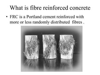
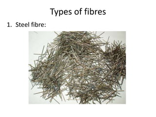
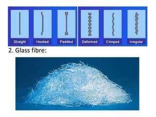
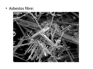
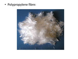
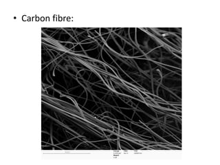
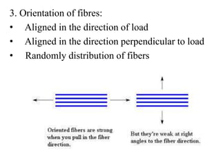
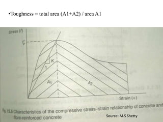
2. What is Fibre?
• Fibre is a small piece of reinforcing material
which increases structural integrity.
Why Fibre ?
Concrete:
• Weak in tension
• Brittle
3. What is fibre reinforced concrete
• FRC is a Portland cement reinforced with
more or less randomly distributed fibres .
11. Factors effecting the properties of FRC
1. Volume of fibres:
• low volume fraction (less then 1%):
Used in slabs and pavement that have large
exposed surface leading to shrinkage cracking
• Moderate volume fraction(between 1 and 2%):
Used in construction method such as shotcrete
• High volume fraction(greater then 2%):
Used in making high performance FRC
12. 2. Aspect ratio of fibre:
= fibre length/fibre diameter
Source: M.S Shetty
13. 3. Orientation of fibres:
• Aligned in the direction of load
• Aligned in the direction perpendicular to load
• Randomly distribution of fibers
14. 4. Relative fibre matrix:
• Fibre should be significantly stiffer than matrix
• Low modulus of fibres imparts more energy
absorption while high modulus of fibres imparts
strength and stiffness.
• Low modulus fibres e.g. nylon, polypropylene
• High modulus of elasticity e.g. steel, glass and
carbon fibres.
15. 5. Workability and compaction of concrete:
• Usage of steel fibres , higher aspect ratio and
non-uniform distribution of fibres will reduce
workability
• Prolonged external vibration fails to compact the
concrete
• These properties can be improved by increasing
water/cement ratio or by using water reducing
admixtures
16. 6.Size of coarse aggregate:
• Restricted to 10mm
• Friction between fibres and between fibres and
aggregates controls orientation and distribution.
7. Mixing:
• Mixing of FRC needs careful precautions to
avoid balling effect and segregation
• Increase in aspect ratio, volume percentage and
size of coarse aggregate will increase the
difficulties.
17. Developments in FRC
1.High fibre volume micro fibre system:
• length – 3mm
• Diameter – 25 microns
• Specific surface > 200 cm2/gram
• Mixing of FRC needs careful conditions to avoid balling
effect
• Sand particles of size not exceeding 1mm
• Low sand to cement ratio.
• Requires large dosage of super plasticizers
• Omni mixer is used for mixing
19. 2. Slurry infiltrated fibre concrete(SIFCON):
• Invented by lankard in 1979
• Pre-placing the dry fibres and cement slurry
is infiltrated.
• Volume of fibres can be increased to 20%
• increase in flexural capacity and toughness.
• used in blast resistant structures
• better suited for three dimensional application
such as zones of reinforcing bars anchorages
20. 3. Slurry infiltrated mat concrete (SIMCON):
• Infiltrating continuous steel fibre mats with a
specially designed cement based slurry.
• Mats are made up of stainless steel.
• Fibre volume is less than that required for
SIFCON, but same flexural strength and energy
absorption.
• Aspect ratio exceeding 500 can be used.
• Since mat is predefined configuration, handling
is minimized and balling effect is reduced
21. • Cracks are small and discontinuous and
possibility of water seepage is low .
• Concrete slurry uses very little water to pack
the mat very tight some of the cement remains
unhydrated.
27. Behaviour of SFRC in Tension
• Effect of incorporating fibres – delay and control tensile cracking
• Fibres (ductile) + matrix (brittle) composite (ductile)
• Sharing of tensile load (most predominant feature of FRC)
until the matrix cracks ( fibre & matrix)
once matrix cracks (fibres)
this mechanism gives rise to favourable dynamic properties
1. Energy absorption
2. Fracture toughness
28. • Mangat reference (1976)
“ The effect of fibres in a cementitious material is principally to
cause relief of tensile stress at the crack tip and prevent unstable
crack propagation”
29. Kelly (1970)
• Investigated the mechanism of pull-out.
• Load-elongation curve of fibres in tension depends on volume
fraction of fibres.
• Response in tension (based on FRC or SIFCON)
stage1: before cracking the composite elastic- (elastic stage)
stage2: after cracking –fibres tend to pull out – sudden change in
load elongation curve.
- if maximum post cracking stress › cracking stress – (multiple
cracking stage)
stage 3: beyond the peak point - failure and/or pull out of fibres
across single critical crack.
• Note : the post cracking strength increases with increase in bond
strength, aspect ratio and volume fraction of fibres.
30. • In the curve OA – debonding of fibre
• In case of short fibres – debonding occurs at max load
• Debondind energy per unit area =
(area of OAB under the stress-strain curve)/(surface area of fibre)
• The additional energy dissipation of fibre concrete results from
debonding energy as well.
Source: santakumar
32. Behaviour of FRC in Compression
• Increase in compressive strength of FRC is marginal and ranges
from 0% to 20%.
• However, post cracking compressive stress-strain response
changes substantially.
• Change is due to Increase in strain at peak load & ductility
beyond ultimate load – higher toughness
• Higher toughness – prevents sudden & catastrophic failures
(especially in case of EQ & blast type of loads)
34. Behaviour of FRC in Flexure
• There are 3 stages of response in flexure
stage1: process zone
- more or less linear response up to elastic limit.
- transfer stress from matrix to the fibres by interfacial shear
- imposed stress is shared between matrix and fibre until
first crack.
stage2: pseudo-plastic zone
- it is the non-linear portion between the elastic point and
max load capacity point.
- stress in matrix is progressively transferred to the fibres.
- fibres pull-out from the matrix (non-linear load-deflection)
- results in multiple cracking
35. stage3: stress free zone
- descending portion following peak strength until strain
limit.
- load-deflection curve represents ability of the fibre
composite to absorb large amounts of energy before failure.
- fibres are completely pulled-out
• Flexural strength of fibre composite is
fc = ultimate strength of fibre composite
fm = max strength of plain matrix (concrete)
C and D are constants determined experimentally
for plain concrete C=1 and D=0
for FRC ultimate strength C=0.95,D=4.95
for FRC first cracking strength C= 0.85, D= 4.95
37. Crack Arresting
• Crack resistance is lower than the ultimate stress
• Once cracking is subjected to coupling impact of increased loads,
material ageing, structure fatigue – increase microcracks
• Microcracks – upward shifting of N-A, tension area of concrete is
lost – decrease of structural rigidity – deterioration of structural
durability.
• Propogation of micropcracks – emergency situation
• Fracture mechanics – stress singularities at crack tips
• Stress intensity factor › critical stress intensity factor of FRC –
Propagation of cracks - functional obsoleteness & structural
failure
40. CASE STUDY
• Research program is funded by National Basic Research
Program of china
• Published in 15 may 2013 in JESTR
41. Case study to arrest cracks
Crack arresting and strengthening
42. • Supposing unilateral crack under pure bending
• Stress concentration factor of edge crack is more than central
penetrated crack under same loading – unstable propagation
• HFRP is bonded to the surface – resists stress concentration of
crack at crack tip– edge crack in to internal eccentric crack
• From the super position principle
where, are stress intensity factors at crack tip A, the
rebar and the HFRP sheet.
• HFRP – one layer of unidirectional CFRP sheet (300 g/m^2) &
one layer of unidirectional GFRP sheet (600 g/m^2)
adhered to the bottom by epoxy
43. Tensile strength is increased by 171% &
fracture elongation is increased by 70%
44.
45. 2 no. of specimens, 8mm dia bars, 3% of nylon (tensile- 6 Mpa)
47. STRESS INTENSITY FACTOR VS CRACK HEIGHT WITH HFRP
•HFRP increases ductility separately by 36% and 106%
48. Mix Design Procedure
• Corresponding to required 28-day field flexural strength of
SFRC – design strength of laboratory mix is determined.
• For known geometry, stipulated volume fraction- w/c ratio is
selected between 0.45 and 0.60
• Depending on max size of agg. & fibre concentration – cement
paste content is determined by mass
• Ratio of FA to CA varies from 1:1 to 1:3, ratio of 1:1.5 is a good
start for volume % of fibre up to 1.5 and length of fibre up to
40mm.
49. • From w/c ratio & paste content – cement & water content
• Fibre content is obtained by taking density of fibres as 7850
kg/m^3
• Total quantity of agg. Is determined as
wt. of agg. = wt. of FRC – ( wt. of water, cement & fibre)
• Quantities of FA &CA are determined by ratio of FA:CA= 1:1.5
• Trial mix is checked for workability by appropriate test.
50. Applications in India and abroad
• More than 400 tones of Shakti man Steel Fibers have been used recently in
the construction of a road overlay for a project at Mathura (UP).
51. • A 3.9 km long district heating tunnel, carrying heating pipelines from a power
plant on the island Amager into the center of Copenhagen, is lined with SFC
segments without any conventional steel bar reinforcement.
52. • Steel fibers are used without rebars to carry flexural loads is a
parking garage at Heathrow Airport. It is a structure with 10 cm
thick slab.
53. Conclusions
• The total energy absorbed in fiber i.e., area under the load-deflection
curve is at least 10 to 40 times higher for fiber-reinforced
concrete than that of plain concrete.
• Addition of fiber to conventionally reinforced beams increased the
fatigue life and decreased the crack width under fatigue loading.
• At elevated temperature SFRC have more strength both in
compression and tension.
• Cost savings of 10% - 30% over conventional concrete flooring
systems.