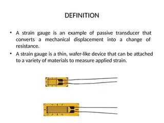
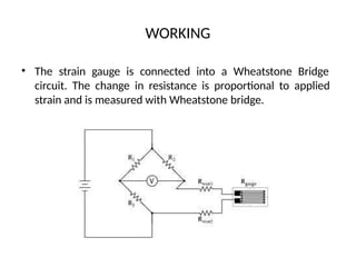
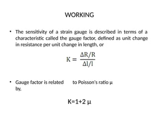
STRAIN GAUGE
PRESENTATION BY:
CONTENTS
• Definition
• History
• Working
• Characteristics
• Types
• Advantages
• Disadvantages
• Application
DEFINITION
• A strain gauge is an example of passive transducer that
converts a mechanical displacement into a change of
resistance.
• A strain gauge is a thin, wafer-like device that can be attached
to a variety of materials to measure applied strain.
HISTOR
Y
A brief history of the Strain Gauge:
• 1856 : Lord Kelvin first reported on a relationship between
strain and the resistance of wire conductors.
• Early 1930s : Charles Kearns made the first notable use of
bonded resistance strain gauges to measure vibratory strains
in high performance propeller blades.
• 1937/8 : Arthur Ruge discovered that small diameter wires
made of electrical resistance alloys could be bonded to a
structure to measure surface strain.
• 1952 : At this time, printed circuits were emerging, and
Saunders-Roe developed the idea of making a strain gauge by
etching the pattern for the gauge from a thin foil.
STRUCTURE
• The majority of strain gauges are foil types, available in a wide
choice of shapes and sizes to suit a variety of applications.
They consist of a pattern of resistive foil which is mounted on
a backing material.
• They operate on the principle that as the foil is subjected to
stress, the resistance of the foil changes in a defined way.
WORKING
• The strain gauge is connected into a Wheatstone Bridge
circuit. The change in resistance is proportional to applied
strain and is measured with Wheatstone bridge.
WORKING
• The sensitivity of a strain gauge is described in terms of a
characteristic called the gauge factor, defined as unit change
in resistance per unit change in length, or
• Gauge factor is related to Poisson's ratio µ
by,
K=1+2 µ
TYPES
Based on principle of working :
• Mechanical
• Electrical
• Piezoelectric
Based on mounting :
• Bonded strain gauge
• Unbonded strain gauge
TYPES
Based on construction :
• Foil strain gauge
• Semiconductor strain gauge
• Photoelectric Strain gauge
MECHANICAL STRAIN GAUGE
• It is made up of two separate plastic layers. The bottom layer
has a ruled scale on it and the top layer has a red arrow or
pointer. One layer is glued to one side of the crack and one
layer to the other. As the crack opens, the layers slide very
slowly past one another and the pointer moves over the scale.
The red crosshairs move on the scale as the crack widens.
ELECTRICAL STRAIN GAUGE
• When an electrical wire is
stretched within the limits of
its elasticity such that it does
not break or permanently
deform, it will become
narrower
and
longer, changes that increase
its electrical resistance end-
to-end.
• Strain can
measuring
resistance.
change
be inferred by
in
PIEZOELECTRIC STRAIN GAUGE
• Piezoelectric generate electric voltage when strain is applied
over it. Strain can be calculated from voltage. Piezoelectric
strain gauges are the most sensitive and reliable devices.
BONDED STRAIN GAUGE
• A bonded strain-gage element, consisting of a metallic wire,
etched foil, vacuum-deposited film, or semiconductor bar, is
cemented to the strained surface.
UNBONDED STRAIN GAUGE
• The unbonded strain gage consists of a wire stretched
between two points in an insulating medium such as air. One
end of the wire is fixed and the other end is attached to a
movable element.
FOIL STRAIN GAUGE
• The foil strain gage has metal foil photo-etched in a grid
pattern on the electric insulator of the thin resin and gage
leads attached,
SEMICONDUCTOR STRAIN GAUGE
• For measurements of small strain, semiconductor strain
gauges, so called piezoresistors, are often preferred over foil
gauges. Semiconductor strain gauges depend on the
piezoresistive effects of silicon or germanium and measure
the change in resistance with stress as opposed to strain.
PHOTOELECTRIC STRAIN GAUGE
• The photoelectric gauge uses a light beam, two fine gratings,
and a photocell detector to generate an electrical current that
is proportional to strain. The gage length of these devices can
be as short as 1/16 inch, but they are costly and delicate.
STRAIN GAUGE
STRAIN GAUGE SELECTION CRITERIA:
• Gauge Length
• Number of Gauges in Gauge Pattern
• Arrangement of Gauges in Gauge Pattern
• Grid Resistance
• temperature sensitivity
• Carrier Material
• Gauge Width
• Availability
• low cost
ADVANTAGES & DISADVANTAGES
Advantages
• There is no moving part.
• It is small and inexpensive.
Disadvantages
• It is non-linear.
• It needs to be calibrated.
APPLICATIONS
• Residual stress
• Vibration measurement
• Torque measurement
• Bending and deflection measurement
• Compression and tension measurement
• Strain measurement
MANUFACTURER
S HANZHONG QUAN YUAN ELECTRONICS
INTEGRATED PROCESS SYSTEMS
GOLDBELL SYSTEMS
VISHAY PRECISION GROUP MICRO
MEASUREMENTS
THANK YOU

straingauge converted mechanical engineering.pptx

  • 1.
  • 2.
    CONTENTS • Definition • History •Working • Characteristics • Types • Advantages • Disadvantages • Application
  • 3.
    DEFINITION • A straingauge is an example of passive transducer that converts a mechanical displacement into a change of resistance. • A strain gauge is a thin, wafer-like device that can be attached to a variety of materials to measure applied strain.
  • 4.
    HISTOR Y A brief historyof the Strain Gauge: • 1856 : Lord Kelvin first reported on a relationship between strain and the resistance of wire conductors. • Early 1930s : Charles Kearns made the first notable use of bonded resistance strain gauges to measure vibratory strains in high performance propeller blades. • 1937/8 : Arthur Ruge discovered that small diameter wires made of electrical resistance alloys could be bonded to a structure to measure surface strain. • 1952 : At this time, printed circuits were emerging, and Saunders-Roe developed the idea of making a strain gauge by etching the pattern for the gauge from a thin foil.
  • 5.
    STRUCTURE • The majorityof strain gauges are foil types, available in a wide choice of shapes and sizes to suit a variety of applications. They consist of a pattern of resistive foil which is mounted on a backing material. • They operate on the principle that as the foil is subjected to stress, the resistance of the foil changes in a defined way.
  • 6.
    WORKING • The straingauge is connected into a Wheatstone Bridge circuit. The change in resistance is proportional to applied strain and is measured with Wheatstone bridge.
  • 7.
    WORKING • The sensitivityof a strain gauge is described in terms of a characteristic called the gauge factor, defined as unit change in resistance per unit change in length, or • Gauge factor is related to Poisson's ratio µ by, K=1+2 µ
  • 8.
    TYPES Based on principleof working : • Mechanical • Electrical • Piezoelectric Based on mounting : • Bonded strain gauge • Unbonded strain gauge
  • 9.
    TYPES Based on construction: • Foil strain gauge • Semiconductor strain gauge • Photoelectric Strain gauge
  • 10.
    MECHANICAL STRAIN GAUGE •It is made up of two separate plastic layers. The bottom layer has a ruled scale on it and the top layer has a red arrow or pointer. One layer is glued to one side of the crack and one layer to the other. As the crack opens, the layers slide very slowly past one another and the pointer moves over the scale. The red crosshairs move on the scale as the crack widens.
  • 11.
    ELECTRICAL STRAIN GAUGE •When an electrical wire is stretched within the limits of its elasticity such that it does not break or permanently deform, it will become narrower and longer, changes that increase its electrical resistance end- to-end. • Strain can measuring resistance. change be inferred by in
  • 12.
    PIEZOELECTRIC STRAIN GAUGE •Piezoelectric generate electric voltage when strain is applied over it. Strain can be calculated from voltage. Piezoelectric strain gauges are the most sensitive and reliable devices.
  • 13.
    BONDED STRAIN GAUGE •A bonded strain-gage element, consisting of a metallic wire, etched foil, vacuum-deposited film, or semiconductor bar, is cemented to the strained surface.
  • 14.
    UNBONDED STRAIN GAUGE •The unbonded strain gage consists of a wire stretched between two points in an insulating medium such as air. One end of the wire is fixed and the other end is attached to a movable element.
  • 15.
    FOIL STRAIN GAUGE •The foil strain gage has metal foil photo-etched in a grid pattern on the electric insulator of the thin resin and gage leads attached,
  • 16.
    SEMICONDUCTOR STRAIN GAUGE •For measurements of small strain, semiconductor strain gauges, so called piezoresistors, are often preferred over foil gauges. Semiconductor strain gauges depend on the piezoresistive effects of silicon or germanium and measure the change in resistance with stress as opposed to strain.
  • 17.
    PHOTOELECTRIC STRAIN GAUGE •The photoelectric gauge uses a light beam, two fine gratings, and a photocell detector to generate an electrical current that is proportional to strain. The gage length of these devices can be as short as 1/16 inch, but they are costly and delicate.
  • 18.
    STRAIN GAUGE STRAIN GAUGESELECTION CRITERIA: • Gauge Length • Number of Gauges in Gauge Pattern • Arrangement of Gauges in Gauge Pattern • Grid Resistance • temperature sensitivity • Carrier Material • Gauge Width • Availability • low cost
  • 19.
    ADVANTAGES & DISADVANTAGES Advantages •There is no moving part. • It is small and inexpensive. Disadvantages • It is non-linear. • It needs to be calibrated.
  • 20.
    APPLICATIONS • Residual stress •Vibration measurement • Torque measurement • Bending and deflection measurement • Compression and tension measurement • Strain measurement
  • 21.
    MANUFACTURER S HANZHONG QUANYUAN ELECTRONICS INTEGRATED PROCESS SYSTEMS GOLDBELL SYSTEMS VISHAY PRECISION GROUP MICRO MEASUREMENTS
  • 22.