Downloaded 11 times


![T.Satyanarayana Switching Theory and Logic Design
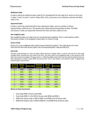
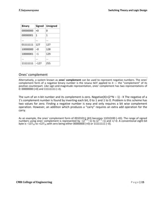
unsigned Sign magnitude 1’s complement 2’s
complement
1111 [15] 0111 [7] 0111 [7] 0111 [7]
1110 0110 0110 0110 [6]
1101 0101 0101 0101 [5]
1100 0100 0100 0100 [4]
1011 0011 0011 0011 [3]
1010 0010 0010 0010 [2]
1001 0001 0001 0001 [1]
1000 0000, 1000[-0] 0000, 1000[-0] 0000 [0]
0111 1001 1110 1111 [-1]
0110 1010 1101 1110 [-2]
0101 1011 1100 1101 [-3]
0100 1100 1011 1100 [-4]
0011 1101 1010 1011 [-5]
0010 1110 1001 1010 [-6]
0001 1111 [-7] 1000 [-7] 1001 [-7]
0000 [0] 1000 [-8]
o Complement/Negate
01011101 number
10100010 invert bits
10100010 + 1 add 1
10100011 2’s Complement
01011101 number
10100011 2’s Complement
1 00000000 (discard carrys in 2’s complement arithmetic)
o Addition
0100 [+4] 0100 [+4]
1101 [-3] 1011 [-5]
1 0001 [+1] [ignore carry] 0 1111 [-1] [no carry]
Signed and Unsigned Arithmetic: (comparisons)
Signed Arithmetic
a) Use: in numerical computation
b) Sign extension required for word size conversion
c) Validity: produces overflow( = signed out-of range) and carry.
CMR College of Engineering P a g e |17](https://image.slidesharecdn.com/unit-1-151002095824-lva1-app6892/85/STLD-Unit-1-17-320.jpg)
![T.Satyanarayana Switching Theory and Logic Design
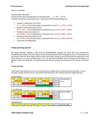
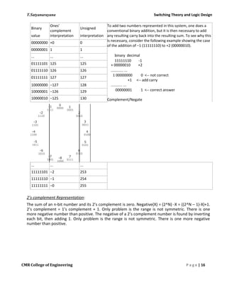
Unsigned Arithmetic
a) Use: in address calculation
b) No negative values
c) No sign extension for word size conversion
d) Validity: only produced carry
( = unsigned overflow = unsigned out-of-range)
Arithmetic Exceptions/Multiword Precision:
Sign Extension:
a) Word size conversion: MSbit of word must be replicated in top of new word.
b) Conversion to smaller word: produces truncation errors, i.e. changed sign
c) Example:
4 bits: 1110 [-2]
8 bits: 1111 1110 [-2] byte
16 bits: 1111 1111 1111 1110 [-2] half word
32 bits: 1111 1111 1111 1111 1111 1111 1111 1110 [-2] word
(register)
Arithmetic Exceptions/Multiword Precision:
Overflow:
a) When a carry occurs from the msb-1 position to the msb and the sign of the is different from
the sign of the two arguments.
b) Overflow can not occur for the addition of two signed numbers with different signs. ( or
subtraction with the same sign)
c) Examples:
0100 [+4] 1100 [-4]
0101 [+5] 1011 [-5]
0 1001 [-7] (9) 1 0111 [+7] (-9)
Carry/Borrow:
a) Occurs during the addition of two unsigned numbers when a carry propagates from the Msbit
of the result.
b) Normally an error for unsigned arithmetic
c) Basis for extended word precision. Words are added/subtracted from LSW to MSW with the
carry from the previous word.
d) Extended word precision for signed number is identical but the MSW addition/subtraction
step uses signed arithmetic.
e) Example:
1100 [12]
1011 [11]
0001 0111 [23] (16 + 7)
CMR College of Engineering P a g e | 18](https://image.slidesharecdn.com/unit-1-151002095824-lva1-app6892/85/STLD-Unit-1-18-320.jpg)


This document discusses the history and development of numeral systems. It begins by explaining the key aspects of a numeral system and some of the earliest systems used, such as unary notation. It then describes the development of place-value systems, including the Hindu-Arabic decimal system. Various base systems are covered, such as base-2 (binary), base-5, base-8, base-10, base-12, base-20, and base-60. The document also discusses weighted and non-weighted binary coding systems, including excess-3 code and gray code. The history of binary numbers is outlined, from early concepts developed by ancient Indian and Chinese mathematicians to its modern implementation in digital circuits.


![Attack surfaces and attack tress[inform]](https://cdn.slidesharecdn.com/ss_thumbnails/lecture03-260108015941-a4dee53b-thumbnail.jpg?width=640&height=640&fit=bounds)


