Downloaded 39 times
![SKIT,Jaipur
| S t e r i o l i t h o g r a p h y a n d i t s a p p l i c a t i o n i n M e d i c a l S c i e n c e
“Stereolithography & its application in Medical Science.”
A
Seminar Report
Submitted in partial fulfillment
For the award of the
Degree of Bachelor of technology
in Department of Mechanical Engineering
(Academic Session 2013-17)
ProjectGuide
Mr. Dheeraj Joshi
(Reader and Dept. Head)
ProjectCoordinators:
Mr. Dinesh Sharma
Mr. Ankit Agarwal
Department of Mechanical Engineering
Swami Keshvanand Institute of Technology, Management & Gramothan.
Submitted By:
Hitesh Sharma
[13ESKME036]](https://image.slidesharecdn.com/report-190303173741/85/Stereo-lithography-Report-1-320.jpg)


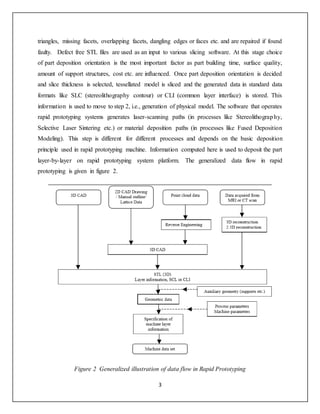
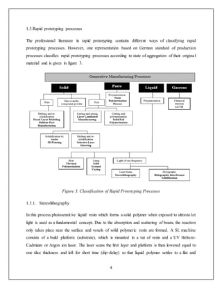
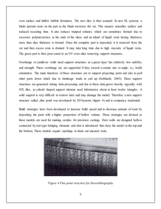
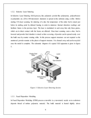

The document is a seminar report on stereolithography and its applications in medical science, submitted for a Bachelor of Technology degree in Mechanical Engineering. It discusses the evolution of 3D printing technologies, particularly focusing on stereolithography, and its significance in creating medical devices and implants. The report includes various rapid prototyping processes, acknowledges contributions from mentors, and outlines the importance of integrating engineering and medical research.


